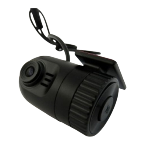
Ecotron YKS6 User manual

Document No.
Revision Date
1/21/2021
13115 Barton Rd, STE H
Whittier, CA, 90605
United States
Document Name
YKS6 Smart Camera User Manual
Contact
info@ecotron.ai
1
YKS6 Smart Camera User Manual

Document No.
Revision Date
1/21/2021
13115 Barton Rd, STE H
Whittier, CA, 90605
United States
Document Name
YKS6 Smart Camera User Manual
Contact
info@ecotron.ai
2
Contents
1 Description............................................................................................................................................3
2 Specs .....................................................................................................................................................3
3 Hardware Settings.................................................................................................................................4
4 Icons Description...................................................................................................................................7

Document No.
Revision Date
1/21/2021
13115 Barton Rd, STE H
Whittier, CA, 90605
United States
Document Name
YKS6 Smart Camera User Manual
Contact
info@ecotron.ai
3
1Description
The YKS6 display can be used together with ADAS devices to display warning information, including
lanes, vehicles, pedestrians, time to collision, etc.
Figure 1. YKS6 Display
2Specs
Dimension
36.9mm * 52.4mm * 53.1mm
Weight
104g
Interfaces
RS232 * 1, VCC * 1
Voltage
Forward voltage: 9~36V
Reverse voltage:<= 36V
Power Consumption
0.1W(typical)
0.15W(peak)
Operation Temp.
-40 ~ 85℃
Storage Temp.
-40 ~ 95℃
Operation Humidity
<= 95%
Table 1. Specifications

Document No.
Revision Date
1/21/2021
13115 Barton Rd, STE H
Whittier, CA, 90605
United States
Document Name
YKS6 Smart Camera User Manual
Contact
info@ecotron.ai
4
Figure 2. Physical Dimensions
3Hardware Settings
1) There are two selection buttons and one function button on the display.
Figure 3. Locations of buttons

Document No.
Revision Date
1/21/2021
13115 Barton Rd, STE H
Whittier, CA, 90605
United States
Document Name
YKS6 Smart Camera User Manual
Contact
info@ecotron.ai
5
2) If you press the select buttons directly, you will go to the volume adjust interface, as shown
below. The figure stands for volume level, ranging from 0 (mute) to 5 (highest). You can adjust the
volume by pressing left and right Selection buttons.
Figure 4. Press the selection button to adjust the volume.
3) When you press the function key, you will go into interfaces that support to customize the display
luminance, headway monitoring and warning time, lane departure warning sensitivity, forward
collision warning enable/disable, and volume adjustment. You can change the interfaces by
pressing the Function button, and when there are no operations within 5 seconds, the display will
exit the customization interfaces.
•Display luminance. All icons will appear on the display, and the figures stand for the luminance
levels, ranging from 1 (lowest) to 5 (highest). The Selection buttons can be used to adjust the
luminance.
Figure 5. Luminance Adjustment

Document No.
Revision Date
1/21/2021
13115 Barton Rd, STE H
Whittier, CA, 90605
United States
Document Name
YKS6 Smart Camera User Manual
Contact
info@ecotron.ai
6
•HMW Time. There will be a red car icon and warning time (in seconds) on the display. The
Selection button can be used to adjust the warning time, that is when the collision time is less
than the warning time, audible and visual warnings will be issued by the system during driving.
This time can also be set in the calibration application.
Figure 6. HMW Time
•LDW Sensitivity. There will be lanes and figures standing for sensitivity on the display, ranging
from 1 (lowest) to 3 (highest), and 0 means LDW feature is disabled.
Figure 7 LDW Sensitivity
•FCW Switch. There will be a flickering red car and figure icons on the display. 0 means the
forward collision warning feature is disabled while 1 means enabled. Selection button can be
used to change the figure.

Document No.
Revision Date
1/21/2021
13115 Barton Rd, STE H
Whittier, CA, 90605
United States
Document Name
YKS6 Smart Camera User Manual
Contact
info@ecotron.ai
7
Figure 8. FCW Switch
4Icons Description
YKS6 will display vehicle, lane, time icons based on the warning details.
Figure 9. Icon Illustration
•The green car icon means there are vehicles ahead. If the distance to the preceding vehicle is too far,
the car icon will not be appearing.
•The green figure stands for the collision time with the preceding vehicle, which will disappear when
the collision time is larger than 3.0 seconds.
•Different icon colors stand for different risk levels: green means relatively safe while red means risky.
•The white lane icons stand for left/right road lanes.
1) No Dangers
When there is no tailgating or lane departure dangers, there will be a green dot on the display.
Figure 10. No Dangers

Document No.
Revision Date
1/21/2021
13115 Barton Rd, STE H
Whittier, CA, 90605
United States
Document Name
YKS6 Smart Camera User Manual
Contact
info@ecotron.ai
8
2) Lane Departure Warning
When the host vehicle drifts out of current lane without turning signals on, and the vehicle speed is
over 50Km/h (speed configurable), the system will issue audible and visual lane departure warnings,
as shown below.
Figure 11. The lane icon will flicker.
3) Headway Monitoring and Warning
When the host vehicle is too close to preceding vehicles, and the host vehicle speed is over 40Km/h
(speed configurable), the collision time icon will appear on the display. When the collision time is
lower than 0.8 seconds, the icons will turn from green to red, and the system will issue audible
warnings.
Figure 12. HMW icon
4) Forward Collision Warning
When the system detects imminent collision dangers, like cut-in, or the large speed discrepancy
between the host vehicle and preceding vehicle, the system will issue forward collision warnings
when the time to collision (TTC) is lower than 2.7 seconds: red car icon flashing on the display, and
rapid audible warnings.
Figure 13. FCW icon

Document No.
Revision Date
1/21/2021
13115 Barton Rd, STE H
Whittier, CA, 90605
United States
Document Name
YKS6 Smart Camera User Manual
Contact
info@ecotron.ai
9
Note:
•HMW is calculated based on the speed of the host vehicle, while FCW is calculated based on
the relative speed of the host vehicle and the preceding vehicle.
5) Pedestrian Collision Warning
When the system detects pedestrian collision dangers, it will issue audible and visual warnings.
There will be red pedestrian icons flickering on the display.
Figure 14. PCW icon
Table of contents
