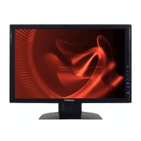
ECU Master ADU-5 User manual

ECUMASTER ADU-5/ADU-7
User Manual
(08/22/2018, version 1.0.101)

Contents
Ecumaster ADU....................................................................................................................4
Characteristics...................................................................................................................5
Technical drawing..............................................................................................................6
Device description ............................................................................................................8
Connector..........................................................................................................................
Connector - description....................................................................................................11
Installation..........................................................................................................................13
CAN bus...........................................................................................................................14
Connecting to ECU..........................................................................................................16
Connecting to CAN bus...................................................................................................16
Connecting using RS232 serial communication..............................................................18
OBD 2..............................................................................................................................1
GPS module.....................................................................................................................20
Ecumaster PMU...............................................................................................................22
Digital inputs....................................................................................................................23
Analogue inputs...............................................................................................................24
USB Flash drive (pen drive).............................................................................................25
Low side outputs..............................................................................................................25
indows software..............................................................................................................26
Pages ..................................................................................................................................36
Creating a page ..............................................................................................................36
Page elements ................................................................................................................38
Adding page elements ....................................................................................................40
Page switching ................................................................................................................48
Startup screen..................................................................................................................50
Objects ...............................................................................................................................51
Gauge..............................................................................................................................51
Classic gauge..................................................................................................................53
Bar graph.........................................................................................................................56
Simple indicator...............................................................................................................5
Text...................................................................................................................................60
Time.................................................................................................................................62
Image...............................................................................................................................63
RPM Bar..........................................................................................................................64
Gear indicator..................................................................................................................65
G-Force............................................................................................................................66
Predictive time graph.......................................................................................................67
Tire temperature graph....................................................................................................68
Tire temperature gradient................................................................................................6
Track record table............................................................................................................70
Rectangle.........................................................................................................................71
Line..................................................................................................................................72
Circle................................................................................................................................73
Textures ..........................................................................................................................74
Inputs ..................................................................................................................................76
Analogue inputs ..............................................................................................................76
Digital inputs....................................................................................................................80
Outputs................................................................................................................................83
Page 2/137

Low side output................................................................................................................83
Analogue output .............................................................................................................83
User lights........................................................................................................................85
User tracks.......................................................................................................................87
Fuel level filter..................................................................................................................8
OBD 2.............................................................................................................................. 0
Outputs............................................................................................................................ 1
orking with CAN buses in ADU.....................................................................................92
Using pre-defined streams from CANX files. .................................................................. 2
Custom CAN streams - CANbus Message Object ......................................................... 2
Custom Can streams - CANbus Message Input............................................................. 5
Custom CAN streams - saving to a .CANX file............................................................... 7
Sending frames by means of the CAN bus (CANbus export)......................................... 7
Processing information in the ADU ................................................................................99
Timers .............................................................................................................................
Tables - lookup tables ...................................................................................................100
Switches - virtual switches, counters.............................................................................102
Numbers - mathematical channels................................................................................103
5. Functions...................................................................................................................106
Alarms................................................................................................................................111
User Lights........................................................................................................................113
Logging channels ............................................................................................................114
Logging to USB memory.................................................................................................116
Permanent meters ...........................................................................................................118
Resetting/changing meter status ..................................................................................11
The min/max value for ECU channels............................................................................120
Panels................................................................................................................................121
Buttons...........................................................................................................................121
Shift light........................................................................................................................122
Autobrightness...............................................................................................................124
Configuration..................................................................................................................125
Protection.......................................................................................................................126
Log.................................................................................................................................127
CAN Bus / Serial setup..................................................................................................127
Lap timing ........................................................................................................................129
Configuration of time measurement with a beacon device...........................................130
Configuration of time measurement with a GPS...........................................................130
Data analysis ................................................................................................................131
Appendix 1........................................................................................................................134
Document history.............................................................................................................135
Page 3/137

Ecumaster ADU
ECUMASTER ADU (Advanced Display Unit) is a universal display designed for motorsports. Unlike
similar devices on the market, the Ecumaster ADU offers a high degree of configurability of the
displayed information and remarkable flexibility for configuring inputs. Equipped with two CAN
buses, the display can easily communicate with other devices (e.g. ECU, GPS, ABS, etc.).
Additionally, up to 8 analogue inputs (e.g. pressure sensors, temperature sensors) and 8 digital
inputs (signals from frequency sensors, beacon etc.) may be connected and configured.
A secondary method of relaying information to the driver is a set of 15 RGB LEDs. These LEDs are
useful for relaying warnings (such as low oil pressure) and as a progressive shift light.
To ensure user comfort in various lighting conditions, a high-quality LCD display was chosen, with
a brightness of 600 cd/m2 for the ADU5 display and 1000 cd/m2 for the ADU7 display. In order to
reduce reflections, the display features an anti-glare coating. The front of the enclosure features
a light sensor that automatically adjusts the brightness of the display to suit current conditions.
The ADU may also be used as a central data logger. All information collected by the display can be
saved on an USB storage device (flash drive, pen drive) recorded at up to 500 Hz per channel. The
ADU features a real-time clock, so all data is stored with the date and time of the recording.
The ADU is a powerful tool for lap timing and driver training. Lap and sector times may be recorded
using an external GPS module, and the driver may be coached in real time using predictive lap
timing. Timing information may be reviewed from logged data after the fact and analyzed.
Page 4/137

Characteristics
General
Working temperature range ACEQ100 (-40 – 85 C)
CPU 32 bits, automotive, 0 MIPS
Reverse polarity protection Yes, internal
Working voltage range 6-22V, robust supply protection compliant to ISO 7637
Housing Anodized aluminium, CNC-machined
IP code IP 60
Connector 1 x 35 position, AMP automotive
Communication with PC CAN bus Ecumaster interface, Peak or Kvaser
Display type TFT 800x600
Brightness of display 5” - 600 cd/m2, 7” - 1000 cd/m2
Inputs / Outputs
Analogue inputs 8 inputs, 10 bits, 0-5 V, software controlled pull-up/pull-down
10K resistor. Al analog inputs can be used as a switches
Digital inputs 8 digital inputs, software controlled input sensitivity (VR, Hall),
software controlled 4K7 pull-up resistors, used for engine speed
sensors, Flex Fuel, wheel speeds, turbocharger shaft speed. All
digital inputs can be used as a switches
Outputs 2 low side outputs (switch to ground), up to 2A
+ 5V output Monitored 5V output for powering external sensors
Communication
CAN Interface 2 x CAN2.0 A/B, 250, 500, 1000 Kbps
CAN streams User-defined
Serial communication RS232 Rx/Tx, AiM protocols, Ecumaster, Hondata Kpro,
Autronic
USB Used for logging to external USB memory
Others
Light Emitting Diodes 15 ultra bright RGB LEDs
Accelerometer/gyroscope 3D accelerometer + 3D gyroscope for the analysis of vehicle
dynamics
Real-time clock Yes, battery powered
Light sensor Yes, for automatic correction of brightness
Temperature sensor Yes, for monitoring device temperature
Page 5/137

Technical drawing
ADU 5 Drawing (all dimensions in mm):
Page 6/137

ADU 7 Drawing (all dimensions in mm):
Page 7/137

Device description
Front view
Position Description
Connection status LED indicating communication with PC. Flashes green when online
Light sensor Light sensor is used for automatic control of the display and light-emitting
diodes' brightness
User led #1- #6 RGB LEDs that can be controlled by user functions (e.g. Alarms,
indicators, etc.)
Shift light Gear change indicator (user configurable)
Page 8/137

Connector
A single 35 position AMPSEAL connector on the rear of the display is used to connect the power
supply, CAN buses and additional sensors or buttons.
A connector and terminals are included with the device. In
order to crimp the terminals, use an appropriate crimping
tool. We do not recommend soldering the wire to the
terminal! If replacement terminals are required, the part
number is AMP 770520-1.
It is critical that terminals are crimped correctly. This type of
connector is very sensitive to the straightness of the
terminal. If excessive force or improper tooling is used, the
terminal will deform and will be difficult to install or remove. The portion of the crimp that supports
the insulation must be circular and of a diameter equal to or smaller than the terminal.
In order to insert or remove terminals, the red terminal lock must be released to the halfway
position, but not removed completely. To eject the red terminal lock, pry the two black latches using
a sharp tool and gently pull the lock. The lock should extend by about 0.5 cm. The teeth prevent
total removal of the red lock from the connector housing. In this position the connector housing is
ready to have terminals inserted or removed.
Terminals should be inserted from the back side of the connector. The mat seal is designed to
allow for the insertion of terminals. Do not attempt to disassemble the back of the connector
housing.
Page /137

Insert the terminal until you hear a click. Take care to only insert the terminal far enough to click.
If the terminal is inserted too far (until it touches the front of the red terminal lock) the lock will be
unable to return to its locked position.
After all terminals have been inserted, push the red terminal lock back to its locked position.
If excessive resistance is encountered, check to ensure that no terminals are inserted too far
forward.
In order to remove a terminal, move the red terminal lock to the halfway position as described
before. Grasp the wire near the connector, and rotate it left and right over a half turn each way to
release the locking tabs, then pull the terminal out of the connector housing.
A video showing the proper assembly and disassembly of this connector can be found here:
https://www.youtube.co /watch?v=uXTk _XV2OY
Page 10/137

Connector - description
Terminal Description
1. USB.GND Ground for the USB port
2. USB.VBUS VBUS signal for the USB port
3. CAN1.H CAN H signal for CAN BUS 1
4. CAN1.L CAN L signal for CAN BUS 1
5. CAN2.H CAN H signal for CAN BUS 2
6. CAN2.L CAN L signal for CAN BUS 2
7. RS232.RXD RXD (receiving) signal for RS232 serial communication. Used for
connection to EMU, Classic, Hondata, Autronic SM4 and AIM compatible
ECUs.
8. RS232.TXD TDX signal (transmitting) for serial RS232
9. Ground sensor Ground for external sensors (e.g. Oil pressure sensor)
10. +5V output +5 power supply for external sensors. Maximum load 400mA
11. Switched 12V +12V signal to switch on the device. The device is internally powered by
the 12 terminal (Battery 12V).
Page 11/137

12. Battery 12V Power supply and backup for the real-time clock when the device is turned
off (when no +12V signal at terminal 11). In the case that there is no 12V
battery power, the real-time clock is powered by an internal battery.
13. USB.DM D- signal to the USB port
14. USB.DP D+ signal to the USB port
15. Analog in 5 Analogue input 5. Measuring range 0-5V
16. Analog in 3 Analogue input 3. Measuring range 0-5V
17. Analog in 1 Analogue input 3. Measuring range 0-5V
18. Digital in 8 Digital input 8
19. Digital in 6 Digital input 6
20. Digital in 4 Digital input 4
21. Digital in 2 Digital input 2. The only input that can be used by a Flex fuel sensor
22. Power ground Device ground used by the AUX outputs and LEDs
23. Ground Device ground
24. Analog in 8 Analogue input 8. Measuring range 0-5V
25. Analog in 7 Analogue input 7. Measuring range 0-5V
26. Analog in 6 Analogue input 6. Measuring range 0-5V
27. Analog in 4 Analogue input 4. Measuring range 0-5V
28. Analog in 2 Analogue input 2. Measuring range 0-5V
29. Analog out Analogue output 0-5V
30. Digital in 7 Digital input 7
31. Digital in 5 Digital input 5
32. Digital in 3 Digital input 3 .This is the only input that will read an AIM beacon
33. Digital in 1 Digital input 1. This is the only input that will support an RPM sensor
34. Aux 1 Low side output. Maximum load 2A
35. Aux 2 Low side output. Maximum load 2A
Page 12/137

Installation
To start the device and communicate with a PC, connect the device's power supply and the
USB2CAN interface to CAN1.
This bus has a constant speed of 1Mbps and one of its functions is communication with a PC.
The above figure shows the minimum connections required to power the device and enable
communication with a PC.
The ADU is programmed through a USB to CAN adapter. Any of these three devices may be used
to enable communication between PC and ADU:
–Ecumaster USBtoCAN (www.ecumaster.com)
–Peak Systems PCAN USB (www.peak-system.com)
–Kvaser USBcan (www.kvaser.com)
All of these interfaces are equipped with DB connectors, where CANL and CANH signals are on
terminals No. 2 and No. 7 respectively.
The diagram also includes a 120Ohm terminator, which is necessary for the correct operation of
the bus (for more information about the terminators see the CAN-BUS section).
IMPORTANT !
Do not connect the +5V output from the CAN interface to +5V ADU!
Page 13/137
ADU
3 CAN1.H
4 CAN1.L
23 Ground
12 Battery
11 Switched 12V
CAN BUS
120 Ohm
USBtoCAN
2
7
USB C

It is recommended to use an interface with galvanic isolation. The CAN bus is a differential signal
bus and in most cases there is no need to connect the interface ground to the vehicle/ADU ground.
If you want to connect an interface ground, measure the potential difference of the interface and
the vehicle. Too large a potential difference can damage the device.
CAN bus
The CAN (Control Area Network) bus was developed to communicate between devices in
automotive environments. Its construction is very simple (only two wires) and its immunity to
interference is very high. In a modern car, there may be dozens of different electronic modules
communicating with the use of the CAN bus.
The ADU device has two CAN buses: the CAN1 bus is used for communication with a PC (requires
an additional interface) and devices that support 1Mbps speed.
Data frames are sent on the network. The network topology should look like the following:
In automotive applications, typical data transmission speeds on the CAN bus are 1Mbps, 500 Kbps
and 250 Kbps. Depending on the speed, the following conditions must be met:
For a speed of 1Mbps:
–the length of the connection cable between the bus and the node must not exceed 30 cm.
–the maximum bus length is 40 m
–the maximum number of nodes is 30
Page 14/137

For a speed of 500kbps:
–the length of the connection cable between the bus and the node must not exceed 30 cm.
–the maximum bus length is 100m
–the maximum number of nodes is 30
Regardless of the speed, the CAN bus must have 120 Ohm termination resistors at both ends.
Additionally, all connections within the bus must be made using twisted pair wires.
It is important that the data transfer speed on a bus is identical for all devices.
ARNING!
Failure to follow these rules will lead to a malfunctioning CAN bus and problems
with communication.
The CAN frame consists of an identifier (ID), the number of transmitted bytes (DLC), and the data.
Depending on the bus type, the identifier may be 11 bits (0x0-0x7ff) or 2 bit (0x0-0x1fffffff). The
number of data bytes may range from 0 to 8
ID DLC Byte 0 Byte 1 Byte 2 Byte 3 Byte 4 Byte 5 Byte 6 Byte 7
Below is a sample CAN frame from a CAN Switchboard device.
ID DLC Byte 0 Byte 1 Byte 2 Byte 3 Byte 4 Byte 5 Byte 6 Byte 7
0x666 8 Analog#1(m ) Analog#2 (m ) CALPOT 1 CAL POT 2 Switch mask Heartbeat
Parameter Description
Analog#1 The voltage for the analogue input #1 0-5000mV, big endian
Analog#2 The voltage for the analogue input #2 0-5000mV, big endian
Switch ask Bitmap of the pressed buttons (1 means pressed)
CAL POT #1 Discrete value of the position of the rotary switch connected to analogue input #1
CAL POT #2 Discrete value of the position of the rotary switch connected to analogue input #2
Heartbeat The counter increases its value by 1 after sending each frame
Page 15/137

Connecting to ECU
To be able to display and log data from the engine management unit, connect the ADU to the CAN
bus of the ECU or its serial port.
When using a CAN bus, you may connect the ECU to the CAN1 (where the ECU CAN bus speed
is 1 Mbps) or to the CAN2 bus where you can define the speed of the CAN bus.
When connecting to an OEM ECU, the typical speed is 500 Kbps (units with a 250 Kbps bus are
rare), which forces us to use a CAN2 bus connection.
Some aftermarket engine management units used in motor sports do not have a CAN bus, but are
equipped with a serial output. This is the case for the EMU, EMU CLASSIC, or Hondata. ADU
supports the following serial formats: AIM, Ecumaster serial protocol, Autronic SM4 and Hondata
serial protocol. For additional information, go to the Serial communication section.
In the case of factory controllers equipped with an OBD2 connector using the CAN BUS (all
vehicles since 2008) it is possible to use the OBD connector to read basic engine operation
parameters. For more information, see OBD2 manual section.
External sensors may be connected to the ADU using the analogue and digital input channels (e.g.
TPS, temperature and oil/fuel pressure sensors, crankshaft position sensor, etc.). As a result, you
can monitor and log parameters that are not supported by the original engine control module.
Connecting to CAN bus
The following diagram shows an example connection of an ECU to the ADU using the CAN1 bus.
Page 16/137

ARNING!
Engine control CAN bus driver speed must be at least 1Mbps. This is due to the
fact that the ADU CAN1 bus supports only this communication speed.
IMPORTANT!
Please ensure the correct bus topology and its proper termination. For more
information see the CAN BUS section.
If the CAN bus speed is different than 1Mbps or if you want to isolate the ECU from the ADU CAN1
bus, please use the CAN2 bus.
Detailed information on connecting specific ECU brands to ADU can be found in the application
notes at www.ecumaster.com. Information about the channel configuration with CAN stream data
can be found in the CAN inputs section.
Page 17/137

Connecting using RS232 serial communication
The ADU display has a built-in RS232 serial bus. In order to connect the ECU via a serial
connection, connect the ECU output (Tx) to the ADU input (Rx) .
IMPORTANT!
To transfer data via serial co unication please use a shielded cable.
The diagram below shows an example of the connection.
Detailed information on connecting specific ECU brands to ADU can be found in the application
notes at www.ecumaster.com. www.ecumaster.com.
To configure the serial protocol (which depends on the ECU connected), select the appropriate
protocol in the CAN Bus/Serial window (Ecumaster serial protocol, AIM, Hondata, Autronic SM4).
Page 18/137

OBD 2
The following diagram shows the connection of the CAN2 bus to the OBD2 bus of the vehicle.
Set the correct CAN bus speed in the CAN Bus/Serial
set-up window (it will usually be 500 Kbps). Then, select
the desired channels in the OBD 2 window.
The channels are divided into two groups: quick (green)
and slow (orange). Quick channels use 66% of the
bandwidth (update rate) while the slow channels use
34%. This means that in the case of an Update rate equal
to 100Hz (data is downloaded by OBD2 at 100Hz) and
when the RPM channel is selected, it will be refreshed 66
times per second (66Hz). If you select an additional
channel (e.g. Throttle position) the refresh rate for both channels will be 33Hz. It should be noted
that not all ECUs are able to refresh the data at a frequency of 100 Hz. In such a case, lower the
“Update rate” parameter.
IMPORTANT!
Not all channels found in the OBD2 window are available for different ECUs.
It is also possible to read a mix of parameters from an OEM ECU, e.g. throttle position and RPM
can be read directly from the CAN bus and the remaining parameters from the OBD2 port. For
further information go to CAN inputs section.
Page 1 /137

GPS odule
The ADU display allows you to use the Ecumaster GPS module to measure lap times on track and
allows data analysis based on the vehicle’s position on the track.
To measure current position of the vehicle, the module uses information from GPS/Glonass
satellites and a built-in accelerometer and gyroscope. The position is refreshed at a frequency of
20Hz.
By default, the GPS module speed is set to 1Mbps. Because of this, it is recommended to connect
the GPS module to the CAN1 bus. A sample connection diagram is presented below:
After wiring the GPS module, it is necessary to configure the ADU. In the CAN bus/Serial setup
options, select the CAN bus that the GPS module is connected to (GPS, CANBus).
The GPS module’s channels are listed in the channel list, beginning with gps.
When using the GPS module, care must be taken to properly mount and calibrate the module.
Due to the use of both a gyroscope and accelerometer for increased accuracy, the GPS module
should be mounted using the supplied anti-vibration pads. The orientation of the module does not
matter, but it must be calibrated after installation. The calibration happens automatically during the
first few hundred meters of driving. Changing the location of the calibrated module should be
followed by a short calibration drive.
For more information about measuring lap times with the GPS module, go to the Lap times
section.
Page 20/137
This manual suits for next models
1
Table of contents
