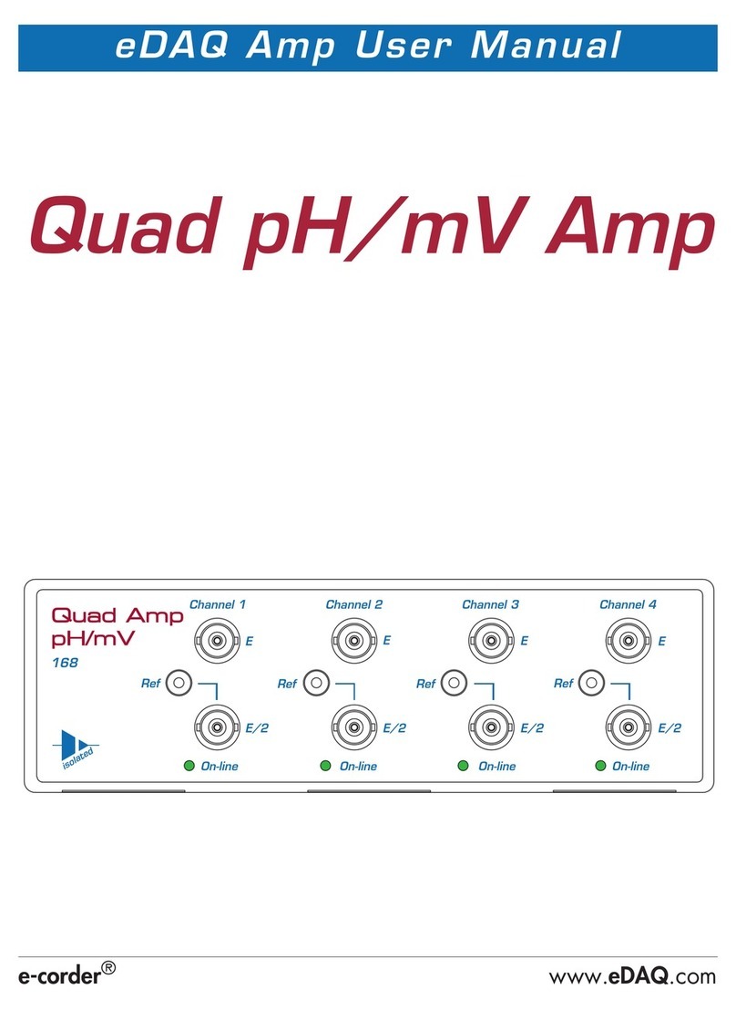
eDAQ Quad Tc/mV User manual

e-corder
®
www.
eDAQ
.com
eDAQ Amp User Manual
Quad Tc/mV Amp
QQuad Amp
Tc/mV
150
Channel 1 Channel 2 Channel 3 Channel 4
On-line On-line On-line On-line
isolated
Cu
+
Cu
+
Cu
+
Cu
+

ii
This document was, as far as possible, accurate at
the time of printing. Changes may have been made
to the software and hardware it describes since
then: eDAQ Pty Ltd reserves the right to alter
specifications as required. Late-breaking information
may be supplied separately. Latest information and
software updates can be obtained from our web
site.
Trademarks of eDAQ
e-
corder
and PowerChrom are registered trademarks
of eDAQ Pty Ltd. Specific model names of data
recording units, such as
e-
corder
201, and
PowerChrom 280, are trademarks of eDAQ Pty Ltd.
Chart and Scope are trademarks of ADInstruments
Pty Ltd and are used under license by eDAQ.
EChem is a trademark of eDAQ Pty Ltd.
Other Trademarks
Mac OS, and Macintosh, are registered trademarks
of Apple Computer, Inc. Windows 98, Windows
Me, Windows 2000, and Windows XP are
trademarks of Microsoft Corporation.
PostScript, and Acrobat are registered trademarks of
Adobe Systems, Incorporated.
All other trademarks are the properties of their
respective owners.
Product: Quad Tc/mV Amp (EA150)
Document Number: U-EA150-0806
Copyright © August 2006
eDAQ Pty Ltd
6 Doig Avenue
Denistone East, NSW 2112
AUSTRALIA
http://www.eDAQ.com
email: [email protected]
All rights reserved. No part of this document may be
reproduced by any means without the prior written
permission of eDAQ Pty Ltd.

Quad Tc/mV Amp
iii
Contents
1
Overview
1
How to Use this Manual 2
Checking the Quad Tc/mV Amp 2
eDAQ Amps 2
2
The Quad Tc/mV Amp
5
The Front Panel 6
The Thermocouple Inputs 6
The On-line Indicators 6
The Back Panel 7
The Signal Outputs 7
I
2
C Connector 7
Connecting to the e-
corder 7
The Quad Tc/mV Amp Self Test 9
Using Chart software 9
Setting up the Quad Tc/mV Amp 9
Previewing the Signal 10
Calibration 12
Automatic Calibration 12
13
Manual Calibration 13
A
Technical Aspects
15
Quad Tc/mV Amp Operation 15
Technical Description 15
B
Troubleshooting
17
C
Specifications
19
Index
21
License & Warranty
23
Quad Amp
Tc/mV
150
Channel 1
On-line
isolated
Cu
+

iv
Quad
Tc/mV Amp

Quad pH/mV Amp
1
CHAPTER ONE
1
Overview
The eDAQ Quad Tc/mV Amp is designed to work with an
e-
corder
system, recording signals from up to four thermocouples (or other low
voltage sources) simultaneously.

2
Quad
pH/mV Amp
How to Use this Manual
This manual describes how to set up and begin using your Quad
Tc/mV Amp. The use of the pH/mV Amp with the Chart software
Thermocouple Calibration extension is discussed. The appendices
provide technical and troubleshooting information.
Checking the Quad Tc/mV Amp
Before you begin working with the Quad Tc/mV Amp, please check
that:
• all items described in the packing list are included; and that
• there are no signs of damage that may have occurred during
transit.
Contact your eDAQ distributor if you encounter a problem.
You should also become familiar with the basic features of your
e-
corder
system, which are discussed in the
e-
corder
Manual
which will
be installed on you hard disk.
eDAQ Amps
The Quad Tc/mV Amp is part of a family of preamplifiers known as
eDAQ Amps.
The Quad
Tc/mV Amp is designed for recording signals from up to four
pH and other potentiometric electrodes. As with other eDAQ Amps, it is
designed to be operated under full software control and is
automatically recognized by Chart or Scope software which controls its
gain range, signal filtering, and other settings.

Chapter 1 —
Overview
3
The range of eDAQ Amps includes the:
•
Quad pH/mV Amp
, suitable for connection of pH, ion selective,
and potentiometric (ORP) electrodes
•
Potentiostat
, a three–electrode potentiostat that can be used for
voltammetric and amperometric experiments. Gain ranges of 20 nA
to 100 mA in 1:2:5 steps.
• Picostat, a high sensitivity three–electrode potentiostat suitable for
use with carbon fibre and other microelectrodes. Current gain
ranges of 10 pA to 100 nA in 1:2:5 steps.
• QuadStat, a four channel, three electrode potentiostat suitable for
use with amperometric biosensors. Current gain ranges of 2 nA
to1 mA/channel in 1:2:5 steps.
• Bridge Amp, suitable for sensors requiring a low drift, high gain
differential amplifier. Also provides DC excitation
• GP Amp, suitable for high output sensors requiring a high
impedance single ended or differential amplifier. Also provides DC
excitation.
See our web site at www.eDAQ.com for more information.

4 Quad pH/mV Amp

Quad pH/mV Amp 5
CHAPTER TWO
2The Quad Tc/mV Amp
This chapter describes how to connect and use your eDAQ Quad
Tc/mV Amp.
IMPORTANT: Always make sure that the e-corder is turned off before
you connect or disconnect the Quad Tc/mV Amp. Failure to do this
may result in damage to the e-corder and/or the Quad Tc/mV Amp.

6 Quad pH/mV Amp
The Front Panel
The front panel of the Quad Tc/mV Amp is shown in Figure 2–1.
The Thermocouple Inputs
The miniature thermocouple input connectors marked ‘Cu’ and ‘+’ of the
Quad Tc/mV Amp provide connection for most types of thermocouple.
The On-line Indicators
When lit, these indicate that the Chart software has located and
initialized the Quad Tc/mV Amp. If the light does not go on when the
software is run, check that the Quad Tc/mV Amp is properly
connected.
Qua
ua
d Amp
d Amp
Tc/mV
/mV
150
Channel 1 Channel 2 Channel 3 Channel 4
On-line On-line On-line On-line
isolated
Cu +Cu +Cu +Cu +
On-line indicator
Thermocouple connector
Made in Australia by eDAQ Pty Ltd.
No user serviceable parts inside.
Refer servicing to qualified service personnel.
Input Output
I C
Bus
I C
2
Channel 4 Channel 3 Channel 2 Channel 1
Temperature signals, BNC connectors
DB–9 pin, I2C connectors
Chassis ground, 4 mm post
Figure 2–1
The Quad Tc/mV Amp
front panel
Figure 2–2
The Quad Tc/mV Amp
back panel

Chapter 2 — The Quad Tc/mV Amp 7
The Back Panel
The back panel of the Quad Tc/mV Amp is shown in Figure 2–2.
The Signal Outputs
The Quad Tc/mV Amp provides four signals, one for each sensing
thermocouple. These signals are accessed on the Quad Tc/mV Amp
back panel via four BNC connectors labelled Channel 1 — Channel 4.
I2C Connector
The back panel, Figure 2–2, has two DB-9 pin ‘I2C bus’ connectors
labelled Input and Output. The Input connector enables connection to
the e-corder (or to the output of other eDAQ Amps). This connection
provides power to the Quad Tc/mV Amp and carries the various
control signals (for gain range and filter selection) to and from the
e-corder. The pin assignments are shown in Figure 2–3.
Connecting to the e-corder
Your Quad Tc/mV Amp will have been supplied with an I2C cable (DB-
9 pin connectors at either end), and four cables with BNC connectors
at either end.
1 5
96
Digital Ground
Regulated –17 V DC
Regulated +8 V DC
Regulated +17 V DC
Power lines
SCL
DSC
SDA
DSD
INT
I2C control signals
15
9 6
Digital Ground
Regulated –17 V DC
Regulated +8 V DC
Regulated +17 V DC
SCL
DSC
SDA
DSD
INT
I2C control signals
Input Output
Figure 2–3
I2C connector pin
assignments

8 Quad pH/mV Amp
First make sure that the e-corder is turned off. Then connect the I2C
cable to the I2C connector on the back panel of the e-corder, and the
other end to the I2C Input connector on the back panel of the pH/mV
Amp. Use BNC cables to connect the signal outputs on the back panel
of the Quad Tc/mV Amp to the front panel of the e-corder as shown in
Figure 2–4 and Figure 2–5.
Check that all connections are firm. Loose connections may cause
failure to recognize the eDAQ Amp by the software, erratic behavior,
or loss of signal.
Multiple eDAQ Amps can be connected to an e-corder. The number
that can be connected depends on the number of input channels on the
e-corder. The initial eDAQ Amp should be connected as shown in
Figure 2–5. The remainder are linked via I2C cables, connecting the
I2C output of one eDAQ Amp to the I2C input of the next. The signal
outputs of each eDAQ Amp are connected to an input channel of the
e-corder.
Output Made in Australia by eDAQ Pty Ltd.
No user serviceable parts inside.
Refer servicing to qualified service personnel.
Input
Channel 4 Channel 3 Channel 2 Channel 1
Made in Australia by eDAQ Pty Ltd.
No user serviceable parts inside.
2
I C Bus
Rated Voltage: 90 - 250 V AC
Refer servicing to qualified service personnel.
50/60 Hz 25 VA
Output
Input 1 Input 3Input 2
Input 4
Trigger
Power
Status
401
Output
Channel 1 Channel 2 Channel 3
168
On-line On-line On-line On-line
isolated
Channel 4
Cu
+
Cu
+
Cu
+
Cu
+
Figure 2–4
Four thermocouples
shown connected to a
Quad Tc/mV Amp and
e-corder 401
Figure 2–5
Back view of Quad
Tc/mV Amp connected
to e-corder

Chapter 2 — The Quad Tc/mV Amp 9
The Quad Tc/mV Amp Self Test
After you have installed the software, connected the e-corder to a
computer as described in your e-corder Manual, and connected the
Quad Tc/mV Amp as described above, a quick check can be
performed:
• Turn on the e-corder and check that it performs its normal
diagnostic tests, as described in the e-corder Manual
• Once the e-corder is ready, open Chart software.
• During initialization, you should see these indicators flash briefly
and then remain lit — the Quad Tc/mV Amp is ready for use.
If the indicators do not light, check your cable connections and repeat
the procedure. If this does not solve the problem, contact your eDAQ
distributor.
Using Chart software
Setting up the Quad Tc/mV Amp
When the Quad pH/mV Amp is connected to an e-corder input and
successfully installed, the Quad Thermocouple… menu command
appears in the Chart software Channel Function pop-up menu, Figure
2–6.
Choosing the Quad Thermocouple… menu command will access the
Quad Thermocouple dialog box (which replaces the normal e-corder
Figure 2–6
Accessing the Quad
Tc/mV Amp controls

10 Quad pH/mV Amp
Input Amplifier dialog box for that e-corder channel — your Chart
Software Manual have details on the Input Amplifier dialog box).
Previewing the Signal
The Quad Thermocouple dialog box, Figure 2–6, allows you to
preview a signal so that you can select the amplification and filter
settings.
The incoming signal is displayed in real time, but is not recorded to
hard disk (once the signal moves across the display area it is lost). Click
the OK button to apply the selected settings.
Signal Display
The input signal is displayed so that you can see the effect of changing
the settings. The average signal value is displayed at the top left of the
display area.
Drag labels and tick
marks to adjust axis
e-corder input
channel number Pause/Resume buttons
Select input
channel
Gain range
(sensitivity)
Preview signal
Average signal
amplitude
Select filter
Select thermocouple type
Figure 2–7
The Quad Tc/mV Amp
dialog box, for
previewing a signal
(Chart software on a
Windows Computer)

Chapter 2 — The Quad Tc/mV Amp 11
You can stop the signal scrolling by clicking the Pause button at the top
right of the display area . Click the Scroll button to resume
scrolling.
You can shift and stretch the vertical Amplitude axis to make the best
use of the available display area (see the Input Amplifier dialog in the
Chart Software Manual for further details). Changes made here update
settings in the main window of the program.
Thermocouple Type
Select the appropriate thermocouple type from this menu. If ‘mV’ is
chosen then the raw millivolt signal will be shown. If any other selection
is made then the ice point corrected thermocouple signal will be shown
in units of mV corresponding to the emf values listed in the NIST ITS–90
thermocouple tables, see http://srdata.nist.gov/its90/main/.
Setting the Range
Use the Range pop-up menu to select the input range (sensitivity) of the
channel. Available ranges are shown in Table 2–1. Signals in excess of
the range value will be truncated.
Filtering
The low pass filter will remove high frequency noise. For most
thermocouple probes filter values of 1 – 10 Hz will be appropriate.
The Mains Filter, , removes 50 or 60 Hz interference due to
mains hum. See the Chart Software Manual for more information. For
most applications it is recommended to have the Mains Filter on.
mV Available ranges (°C) for various thermocouple types
B E J K N R S T
±20 1820 290 360 485 585 1680 1760 250
±10 1500 150 180 250 320 960 1040 115
±5 1020 80 95 120 170 550 580 60
±2 630 35 40 50 75 260 265 30
Table 2–1
Ranges available for
different input settings.

12 Quad pH/mV Amp
Units Calibration
Clicking the button access the Units Conversion dialog box.
For more information about Units Conversion, see the Chart Software
Manual. This type of calibration should only be used for small
temperature ranges that can be calibrated with only two accurately
known temperature sources.
See the next section for calibration of probes, without the need of
accurately known temperature sources.
When calibration is required over a wide range of temperature and
several accurately known temperature sources are to be employed then
use the Multiple Point Calibration extension.
Calibration
Automatic Calibration
The Thermocouple extension is a Chart software plug-in that adds the
‘Thermocouple...’ command to the Chart channel pop-up menus. The
latest version of the extension is available at
http://www.edaq.com/chart_extns_list.html
This extension:
• allows the user to select the type of thermocouple (B, E, J, N, K, R,
S or T) being used;
• applies a polynomial correction to convert the voltage signal to
degrees (°C, °F, or K) according to the thermocouple ITS-90 tables,
see http://srdata.nist.gov/its90/main/
The resulting temperature values will usually be accurate within the
tolerance of the thermocouple being used — consult your thermocouple
probe documentation. In most cases thermocouples conform to either
the ANST/ANSI E230 Standard, or Special, Limits of Error, see
Table 2–2. In some cases, especially over limited temperature ranges,
manufacturers may guarantee better tolerances.

Chapter 2 — The Quad Tc/mV Amp 13
Manual Calibration
If known temperature sources are available then very accurate
calibration can be achieved using the raw mV signal setting. The signal
can be calibrated over small ranges with a linear function using the
Chart software Units Conversion feature (see the Chart Software
Manual). Over wider ranges the Multipoint Calibration extension
software plug-in can be used, see
http://www.edaq.com/chart_extns_list.html
Tc
Type
Temperature Range Limits of Error
°C °F Standard Special
T–200 to –66 –328 to –87 ±1.5% —
–66 to 0 –87 to +32 ±1°C, ±2°F —
0 – 133 32 – 270 ±1°C, ±2°F ±0.5°C, ±1°F
133 – 350 270 – 662 ±0.75% ±0.4%
J0 – 293 32 – 559 ±2.2°C, ±4°F ±1.1°C, ±2°F
293 – 750 559 – 1382 ±0.75 0.4%
E–200 to –100 –328 to –148 ±1% —
–100 to 0 –148 to +32 ±1.1°C, ±3°C —
0 – 340 32 – 644 ±1.7°C, ±3°F ±1°C, ±2°F
340 – 900 644 – 1652 ±0.5% ±0.4%
K–200 to –110 –328 to –166 ±2% —
–110 to 0 –166 to +32 ±2.2°C, ±4°F —
0 – 293 32 – 559 ±2.2°C, ±4°F ±1.1°C, ±2°F
293 – 1250 559 – 2282 ±0.75% ±0.4%
N0 – 293 32 – 559 ±2.2°C, ±4°F ±1.1°C, ±2°F
0 – 1250 559 – 2282 ±0.75% ±0.4%
R, S 0 – 600 32 – 1112 ±1.5°C, ±3°C ±0.6°C, ±1°F
600 – 1450 1112 – 2642 ±0.25% ±0.1%
B870 – 1700 1598 – 3092 ±0.5% —
Table 2–2
Limits of Error for
Thermocouples,
Reference Junction
0 °C (32 °F)

14 Quad pH/mV Amp

Quad pH/mV Amp 15
APPENDIX A
ATechnical Aspects
This appendix describes the some of the important technical aspects of
the Quad Tc/mV Amp. You do not need to know the material here to
use the Tc/mV Amp. Please remember that user modification of the
equipment voids your rights under warranty.
Quad Tc/mV Amp Operation
The Quad Tc/mV Amp, and other eDAQ Amps, have been designed to
be used with an e-corder system. The Tc/mV Amp provides:
• high impedance, electrically isolated inputs suitable for direct
connection to most thermocouples;
• cold junction compensation;
• software controlled filtering of the signal;
• software selectable gain ranges.
Technical Description
As with other eDAQ Amps, all internal functions of the Quad Tc/mV
Amp are controlled from the e-corder by sending information on a
special communications connection called the I2C (eye-squared-sea)
bus. This connection supplies power to the eDAQ Amp as well. eDAQ
Amps are connected to the analog input channels of the e-corder via
BNC-to-BNC cables, through which the amplified and filtered signal is

16 Quad pH/mV Amp
sent to the e-corder. The overall operation of the pH/mV Amp can be
better understood by referring to Figure A–1.
The thermoucouple signal is first amplified (× 100) and then passed
though an isolation transformer. The signal is then ice point corrected,
low pass filtered and then sent to the e-corder for secondary
amplification and filtering.
Front Panel Back Panel
Online indicator
Tcconnector
I2C input
I2C output
Tcsignal
I2C interface
Low pass filter
×100
Gain adj
Calibration
microprocessor
Tcsignal
Tcsignal
Tcsignal
Low pass filter
Low pass filter
Low pass filter
Quad DAC
Tcconnector
Tcconnector
Tcconnector
×100
×100
×100
× 1
×1
×1
Isolation
×1
Ice point
reference
+
+
+
+
Isothermal block
Temperature
sensor
Figure A–1
Block Diagram of the
Quad Tc/mV Amp
Table of contents
Other eDAQ Amplifier manuals
