EDG Fv Plus Sinter User manual

Manual
CAPA

Manual 1
Date of manufacture
200
Serial Number
Vacuum Furnace
1Recepting
Theequipmentispackedseparatelyfromthevacuumpump,checkifyouhavetwo
boxes if you have acquired the furnace and the pump. Check the general
conditions of the package, if any damage is noticed contact the company
immediately which will provide guidance on how to proceed. We remind you that
the equipment is shipped at the purchaser's account and risk and it is insured by
theconveyor.
1.1The FV-PLUS package should include:
A)Afurnacesettledininjectedfoam.
B)Arigidmat-I–Pic-5-Item-(24).
C)Asoftmat.
D)Asetofisothermalpins.Pic-5-item-(25).
E)Instructionmanual.
F)Warrantydeed.
Manual
2
1.1The FV-PLUS package should include:
A)Afurnacesettledininjectedfoam.
B)Arigidmat-I–Pic-5-Item-(24).
C)Asoftmat.
D)Asetofisothermalpins.Pic-5-item-(25).
E)Instructionmanual.
F)Warrantydeed.
NOTE: If you have acquired the furnace without the pump, please do not consider
thematerialmentionedonitem(1-2).
1.2The vacuum pump package should include:
G)Thevacuumpump
H)A1.5mN.P.T.hose
I)Metallicclamps.(2pieces).
J)Rubber,floorinsulatingcapsforfixation(4pieces).
K)Labelsforconnectionsidentification.
!Warning: The FV-Plus-Sinter furnace needs to have the vacuum
pumpalwaysconnectedtothefurnaceevenwhenthevacuumisnotusedfor
the burn, as it happens with the sintering/infiltration. For this procedure the
S.A.L.V® Sistema deAquecimento de Longa Vida (long life heating system) requires
thevacuumpumptohelpwiththeaircirculationinsidethemuffle,therefore having its
heatingelementdurabilityincreased(resistance).
!Note: Not checking the procedures above will interfere on the
equipmentcorrect working and also guarantee will belost. Keep thepump
alwaysconnectedandinperfectworkingconditions.
2S.A.L.V. SYSTEM
Your Fv-Plus-Sinter has highly technological devices that allow it to perform 3
functions perfectly: traditional ceramic burn, sintering and infiltration of alumina-
glass composites. When sintering alumina, the lining used heated over 500º C
releasessub-productswhichareabsorbedbythemuffleundervacuumandcan

Manual
contaminate the ceramic, staining and fissuring it during the sintering process.
Long periods under high temperatures (1,180°C) in pressurized chambers
(vacuum muffles) can shorten the heating resistance useful life. The S.A.L.V.
systemwasspeciallydevelopedtoovercomesuchproblems
S.A.L.V.®Pat.Pending.
SistemadeAquecimentodeLongaVida(LongLifeHeatingSystem)
Twoyearsguaranteeathightemperatures
The metallic alloys used as heating resistance have chemical elements in its
composition that, when heated and in contact with air, create an oxide adherent
layerwhichprotectsthemfromoutwear.
In ceramic furnace muffles, the process for the oxide layer formation can be
impairedduetotheresistanceimprisonmentandtothevacuumoperation.
TheexclusiveS.A.L.V.system,developedandpatentedbyEDG,promotesairflow
inside the quartz pipe that supports the muffle resistance. This flow renews and
maintains the protective oxide layer, increasing the useful life of the resistance at
hightemperatures.
This exclusive technological advance allowed EDG to extend the guarantee to 2
yearsforthefurnacesequippedwiththissystem.
To endure the high temperatures involved in the processes, the sensor (termopar)
should be made of platinum which, on the other hand, is not adequate for low
temperatures and for the necessary speed for eliminating water during the
sinteringprocess.
Ahigh level software was developed to compensate theplatinum limitations in low
temperatures. Due to the characteristics of the sintering process, new thermal
insulating materials were used and an efficient ventilation system keeps the
componentstemperatureunderadequatevalues.
3Main characteristics
• Quartz muffle with thermal insulation ceramic mat molded through low thermal
massvacuum,whichinsuresperfecttemperaturehomogeneity.
•S.A.L.V®SistemadeAquecimentodeLongaVida(longlifeheatingsystem)
• Muffle forced ventilation for sintering/infiltration, which eliminates stains and
minimizesfissuring.
•50programs:39forceramicand10forsintering/infiltration.
•Exclusive4stagesmufflemovablesystemtofacilitatethepositioningofworks
3

Manual
doneontheburnplatform.
•Managementbymicroprocessing.
•Easyoperationandvisualizationoftheburnparameters.·
•Nonvolatilememorykeepsthelastprograminuse.
•Ambientworkingtemperatureat1,100°Cforceramicand1,180°C
forsintering/infiltration.
•Maximumtemperaturelimiterat1,200°C
•Linearheatingspeedfrom0.1to70.0°C/min.
•Thyristoredpowercontrol
•Burntimeforceramicfrom0to30minutes.
• Burn time for sintering/infiltration from 0 to 9 hours and 59 minutes.v Decreasing
timevisualization.
•Vacuumtimefrom0to30minuteswithdecreasingtimevisualization.
• Automatic or manual (which can be activated ant any stage of the process)
vacuumoperation
•Safetysystemsprotecttheequipmentfromoperationmistakesordefects.
•Flashingandbeepingsignsofallprocesssteps.
•Toavoidambienceheating andsaveenergy,analarm willsoundafter 10minutes
if the equipment is not being operated and a “Prot” message will also be displayed
warningthatthemuffleshouldbepartiallyandmanuallyclosed.
•Quickcooling.
•Operationtimetotalizer.
•Lowcostmufflereplacingsystem.
•Electronicsystemforcedventilationkeepsthecomponentssafe.
4Installing
Thenumbersinparenthesesrefertothepicturesthatfollow.
Your Fv-Plus-Sinter should be far from curtains and inflammable material. A
furnace is a heat generator which needs to be dissipated; otherwise its
components will be overheated. Therefore, place the equipment at a ventilated
area which allows free air circulation. It is advisable to leave a 15cm clearance
betweenthefurnaceandanythingthatcanimpairtheventilation.Placethefurnace
farfromtapsorbasinswhichcansprinklewaterovertheequipment.
4

Manual
2
1
3 4
5
Pic.1 Pic.2 7
6
01-Networkvoltageidentifier/powercable.
02-Fuseholder.
03-Serialcommunicationportforcheck-up(technicalassistance)
04-Vacuumhoseconnection.
05-Socketforpluggingthevacuumpump.
06-Muffleventilation.
07-Mainswitchon/off.
4-1)Networkvoltageidentifier/powercable.
4-1) Check if your network voltage is the same as the one shown on the furnace
labelPIC-1-Item(1).
4-2) Install the furnace into an exclusive electrical network using 6mm wiring to a
110voltsnetwork,or4mmwiringtoa220voltsnetwork.
4-3) Never connect the furnace to the same network in which other furnaces,
compressors, electrical taps or any other high electricity consumption devices are
alreadyconnected.
4-4)Checkifthe outletinwhichthefurnacewillbepluggedinis inperfectcondition
andofgoodqualitytobearatleast20amperes.
4-5) Connect the grounding end (round pin) to a grounding rod and never to the
electricalnetworkneutral.
NOTE: Not checking the procedures above will interfere on the equipment
correctworking,onitsguaranteeandalsoontheoperatorsafety.
4-6)Ifyourelectricalnetworkisveryinstable(thelightsflashalot),itisadvisableto
use a voltage regulator such as a saturated autotransformer with at least 2kw
capacity.Neveruse,byanymeans,regulatorsusedincomputers.
5

Manual
apropriadosparaestaaplicação.
4-7) Connect the vacuum hose to the furnace PIC-1 item (4). Plug the vacuum
pump power cable to the outlet which is at the backside of the furnace PIC-1 Item
(05).
5Control panel
5-1) The control panel has a digital display with four red numeral digits which
provideseasyidentificationoftheprogrammingfunctionsandrecordmonitoring.It
indicatessomemessagesofthesafetyprocesssuchassystemflawandoperation
mistakes.
5-2) It has a touch sensitive thin layer which makes the activation of its keys and
functionseasier.
5.3Identifying the keys and its functions
8 9 10 11 12 13 14 15 16 17 18 19 20 21 22
(08)4digitsdisplay.
(09)Parametersprogrammingadjustmentkeys
(10)TemperaturekeyT2,finalburn.
(11)TemperaturekeyT1,pieceentry.
(12)Heatingspeedkey(veloc.2).A2.
(13)Burntimekey(baseline).Pat-2.
(14)VacuumtimekeyVac-2.
(15)Databaserecipeskey.
(16) Muffle opening and closing mode key (0 to 9
min).
(17)Databaserecipesavingkey.
(18) Start / stop, key to begin and finish the burn
process.
(19)Manualvacuumsystemkey.
(20) Database recipes access key, unlocks the
“saveandread”(salvareler)functions.
(21)Equipmentmainswitch.
(22)Analogvacuumindication.
6
Manual
6System start-up
6-1) Plug the furnace into an exclusive and of good quality socket which should be
correctly grounded to a copper rod and never to the electrical network neutral.
Check if the network voltage is the same as the one in the equipment, which is
shownonthepowercablelabelorprintedatthefurnacebackside. Pic-1item(01).
6-2)Turnthe main switch on Pic-3 item (21) and waitfortheequipment to start-up.
Four screens will be visualized in a sequence showing the complete equipment
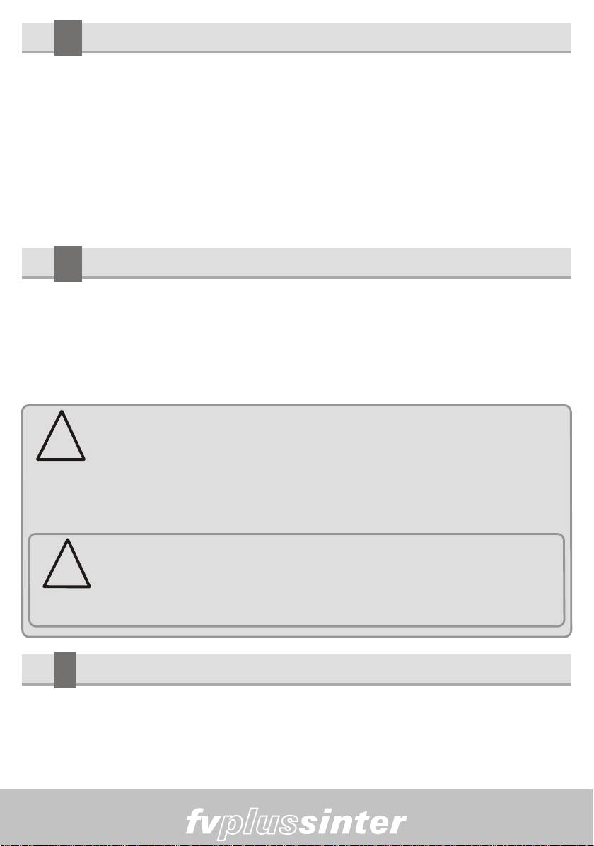
6-3) SCREEN-1 -> The message (EDG) can be visualize
don the first screen as the system checks its functions and
performsthefirstconfigurations.
INICIALIZAÇÕES
LIBERA VÁCUO
TEMP-AMBIENTE
VERSÃO-PROGRAMA
6-4) SCREEN-2 -> On the second screen, the current
program version can be seen for product manufacturing
6-5) SCREEN-3 -> The message (Ar) can be seen on the
third screen and the program waits for 30 seconds for the
airtoreturntothemuffle.
6-6) SCREEN-4 -> On the fourth screen, after the
checking-up is done, the system loads the sintering
standard no. 40 recipe (padrão de sinterização n. 40) and
willkeepwaitingforthenextinstructionbytheoperator.We
remind you that for sintering, the furnace will only heat up
after the (start) command is activated by the operator, therefore the temperature
shownonthedisplaywillbeclosetotheambiencetemperature.
6-7) The furnace must not start the heating process without the burn platform
moldedinceramicfiberputonthebase,PIC-4item(23)otherwisethesealringand
the base will be seriously damaged. Use adequate accessories according to the
wantedproceduresPIC-5.
7

Manual
6-8)PIC-4–AccessoriesforSINTERINGandINFILTRATIONburn.
A)Usetherigidmat-I,item(24)ontheplatform,item(23)
6-9)PIC-5–AccessoriesforconventionalCERAMICburn.
B)Usetherigidmat-I,item(24)ontheplatform,item(23).
C)Useisothermalpinstosupportthepiece,Item(25).
20 24 25
7Programming ceramic recipes
7-1) For better explanation, we will follow practical examples for conventional
ceramic,sinteringandinfiltrationrecipes.
Starting from the ambient temperature, raise it to T1 = 620°C that is the furnace
entrytemperature.
-Keepthistemperatureuntiltheoperator'scommandtostarttheburn.
-Themuffleclosingprocess(preheating/drying)shouldtakeabout5minutes.
-Theburntemperatureis900°C.(T2).
Note: Place the piece on the isothermal pins ends in a way that it can be heated
from all angles; this procedure improves the burn uniformity. Keep the piece on the
thermalcenter.
8

Manual
ABRE FECHA
620 60 ABRE 900 55 01:00 00:30 1 5
EX-1 RECIPE MODEL – CONVENTIONAL CERAMIC
SECAGEM MANUALTEMP-1
ºC VEL-1
Fixo PAT-1
Mufla TEMP-2
ºC VEL-2
Fixo PAT-2
Mufla VAC-2
min
EX - 1 MODELO DE RECEITA - CERÂMICA CONVENCIONAL
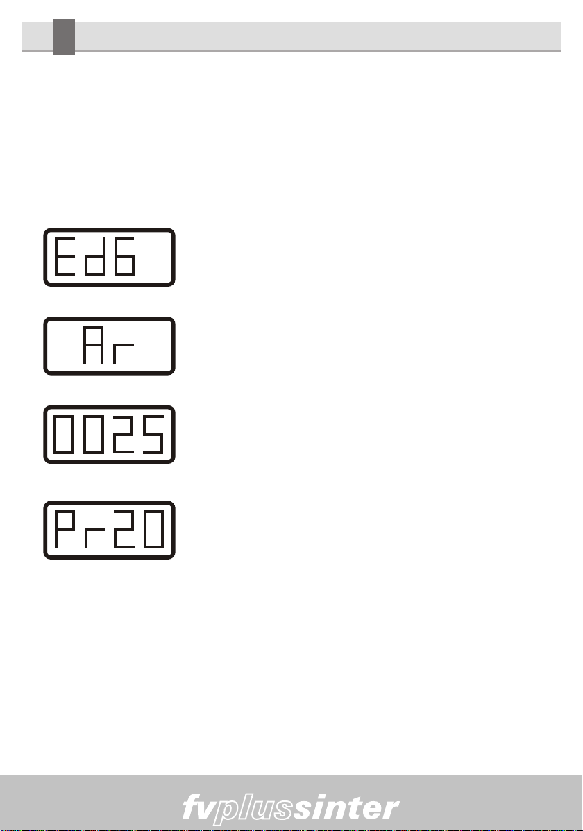
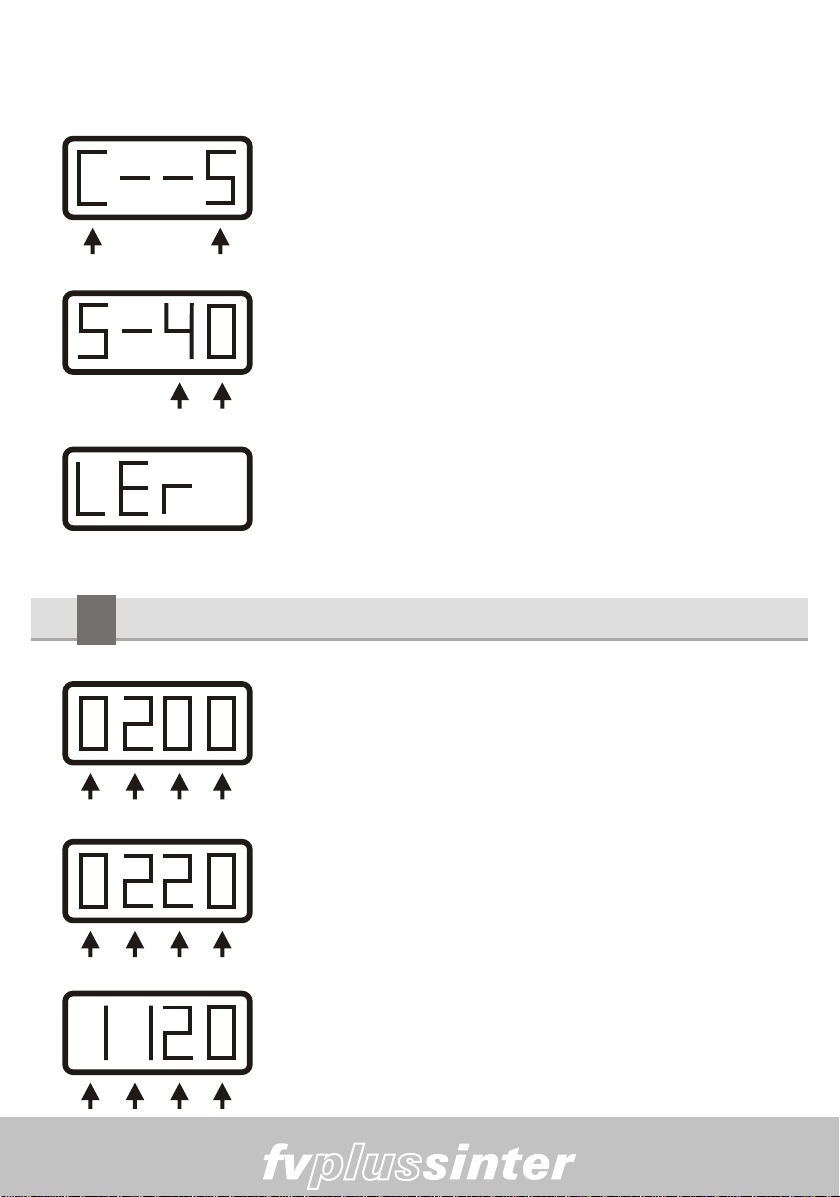
7-2) When activating the PROG. (20) key, the message “C--S” (“C” stands for
Ceramic while “S” stands for sintering/infiltration) will be shown on the display
askingyoutochoosebetweenceramicorsintering/infiltrationprocess.
-TheheatingspeedbetweenT1andT2shouldbe55°C/minute.
-Theburntimewillbe1minute.
-Thevacuumshouldturnthemuffleclosingonandturnitoff30
secondsaftertheburntimehasstarted.
-Aftertheprocessisfinished,thepieceshouldberemovedin1minute.
7-3) Using the Parameters programming adjustment
keys (9) activate the arrow below the letter “C” informing
thatwearegoingtoworkwithceramic.
SEL- PROGRAMA
T2 = 900ºC PAT-2 = 1:00
VAC-2 = 0:30
VEL-2 = 55ºC
T1 = 620ºC
RESFRIAMENTO
NATURAL
MUFLAABERTA
SECAGEM NO ESTÁGIO (4)
CURVA DE AQUECIMENTO
CURVA DO VÁCUO
LEGENDA
9
Manual
CERÂMICA 7-4) Next the display will show “C-01”, which is the
number of the ceramic standard recipe that serves as a
base for programming the next recipes. The arrows (09)
below the number will be used to select the desired
recipe,inthiscase(01).
LER RECEITAS 7-5) Confirm the reading operation activating the “Ler”
(“read”) key (15) this message will be kept on the display
whiletherecipeisbeingloaded.
7-6) Start the programming for a new recipe taking as base the ceramic standard
recipethathasbeenloadedinthememory.
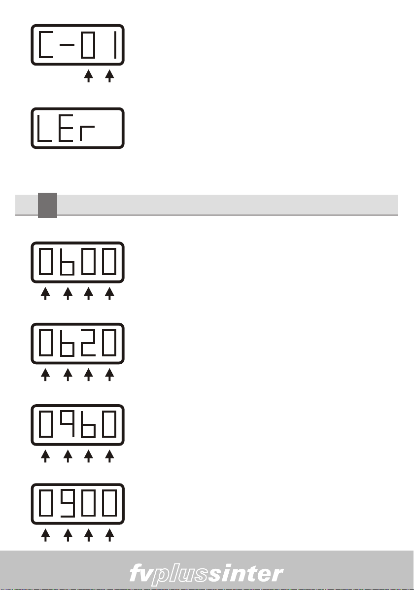
7.7T1 And T2 Temperature adjustment
7-8)Temperatureadjustment-T1
Activate the T1 (11), key and the display will show the
programmed temperature of the standard recipe that
comesfromthefactory“0600”.
PROG - TEMP - T1
7-9) Next, activate the parameters adjustment keys (09),
one for each digit showing on the display the desired
value for T1 of 0620°C. The furnace will heat until this
temperature.
TEMPERATURA - T1
7-10)Temperatureadjustment–T2
Activate the T2 (10) key, and the display will show the
programmed temperature of the standard recipe that
comesfromthefactory“0960”.
PROG - TEMP - T2
TEMPERATURA = T2
7-11)Next,activatetheparametersadjustmentkeys(09),
one for each digit showing on the display the desired
valueforT2of0900°C.
10
Manual
7.12 Heating speed adjustment VELOC-2
Note: We remind you that for ceramic recipes at ambient speed theT1 is fixed at
60ºC/minute.
7-13) Activate the Veloc. (12) key and the display will
show “A060” degrees/minute, which is the standard
recipeheatingspeedthatcomesformthefactory.
PROG - VELOC - 2
VELOCIDADE 2 7-14) Next, activate the parameters adjustment keys
(09), one for each digit showing on the display the
desiredvalueof“A055”degrees/minute.
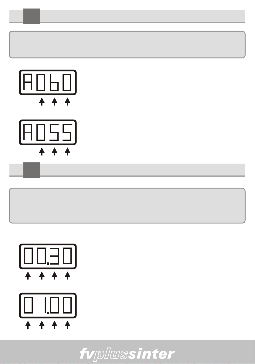
7.15 Burn time adjustment – T2 - BASELINE
Note:Theburntimeoftheceramicprocessesareshowninminutesandseconds.
Forexample:00.30correspondstothirtyseconds;05.35correspondsto5minutesand
thirty-fiveseconds.
PROG - VÁCUO - T2 7-16) Activate the burn time (13) key and the display will
show “00.30” seconds which is the standard recipe burn
timethatcomesfromthefactory.
PROG - PATAMAR -2 7-17) Next, activate the parameters adjustment keys
(09),oneforeachdigitshowingonthedisplaythedesired
valueof “01.00”minute.
11

Manual
7.18 Vacuum time adjustment – VAC-2
7-19) Activate the vacuum time (14) key, and the display
will show “00.00” minutes which is the standard recipe
vacuumtimethatcomesfromthefactory.
TEMPO - VÁCUO - T2
7-20) Next, activate parameters adjustment keys (09),
one for each digit showing on the display the desired
valueof“00.30”seconds.
PATAMAR - T2
NOTES ABOUT THE VACUUM
A)Thevacuumtimecanneverbehigherthantheburntime,ifthevaluefor thevacuum
timeishigherthanthevaluefortheburntime,thefurnacewilldetermineforthevacuum
timethesamevalueastheburntime.
B) Vacuum time the same as “00.01” (1-segundo) indicates that the vacuum will be
performed on the heating ramp between T1 and T2. When the T2 temperature is
reachedthevacuumwillbeturnedoff.
C) ) Vacuum time the same as “00.00” (zero) indicates that the vacuum will not be
performedatanytimeduringtheburnprocess.
D) Vacuum time higher than (1-second) Ex: ”00.30” indicates that the vacuum will be
performedontheheatingrampusingthebaseline.
7.21 Manual vacuum adjustment sim/não (yes/no)
This key is used when one wants to change the vacuum time
duringtheburn.
Activate the manual vacuum key (19) when you want to start or
interrupt the vacuum at any stage of the process, the pump will
perform the desired function over any previous programming.
When the LED above the key is on it means that the pump is activated. When the
LEDisoffitmeansthatthepumpisdeactivated.
VÁCUO
MANUAL
12
Manual
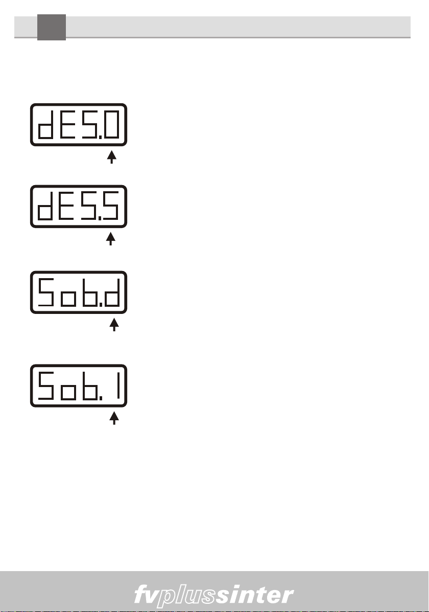
7.22 Programming the drying – entry/exit
The muffle closing and opening can be programmed independently Ex: (Sob.1) e
(dES.d).
FECHA / DESCE 7-23) Activating the key (16) once and the display will
showthemessage“dES.0”.
Activating the parameters adjustment key (09) below “0”
wechoosethedesiredpositionforthemuffleclosing.
FECHA / DESCE
7-24) In this case, on the position “5” the piece entry will
take about 5 minutes to complete the course through the
4stagestoclosethemuffle.
ABRE / SOBE 7-25) Activating the Open/Close (Abre/Fecha) key (16)
twice, the display will show the message “Sob.d”.
Activating the parameters adjustment key (09) below “d”
we choose the desired position according to the table
below.
7-26) In this case, on the position “1” the piece entry will
takeabout 1 minute to complete the course through the 4
stagestoopenthemuffle.
ABRE / SOBE
7-27)Onthepositionzero“0”therewillnotbecountingtimeforclosing.
On the following positions the course times through the 4 stages are approximate:
EX: “1” = 1 minute, 2, 3, 4, 5, 6, 7, 8, 9 minutes, according to the table beside. For
each stage an alarm will sound warning the operator that to move the muffle
articulated to the next position until the whole opening or closing course is
completed.
13

Manual
S 0 . D 0
S 1 . D 1 1 Minuto
S 2 . D 2 2 Minutos
S 3 . D 3 3 Minutos
S 4 . D 4 4 Minutos
S 5 . D 5 5 Minutos
S 6 . D 6 6 Minutos
S 7 . D 7 7 Minutos
S 8 . D 8 8 Minutos
S 9 . D 9 9 Minutos
TABLE FOR ASCENT AND DESCENT -
DRYING
ABRE / FECHA
SOBE / DESCE
MUFFLE MANUAL COURSE, BY OPERATOR
Zero não conta tempo
Entrada e saída da peça
TEMPO APROXIMADO
7.28 Muffle course examples in the 4 closing stages
4º - Entry or exit stage
04
Pic.10
3º - Entry or exit stage
03
Pic.09
1º - Entry or exit stage
01
Pic.07
2º - Entry or exit stage
02
Pic.08
14

Manual
Burn position
Pic.06
7-29)PIC-06indicatesthatthemuffleis
on the correct position to begin with the
burn process. The vacuum pump will
be activated and the operator will keep
pressing down the muffle puller for
someseconds topromotethe chamber
sealing and then start with the vacuum
action.
8Programming sinterin / Infiltration recipe
Ex2: Infiltration/Sintering – Process description
8-1) The piece to be infiltrated/sintered is placed on the burn platform and should
dry for 1 minute. From ambience time, go up to T1 at 220°C at the speed of
10.5°c/min.Keepusingthistemperaturefor10minutes.
Next,raise thetemperaturetoT2 at 1,080°Catthe speedof35°C/min. Keep using
thistemperaturefor1hour.Thepieceexitshouldoccurin2minutesafterthat.
Note: Thesintering/infiltrationprocessesdonotusevacuum.
ABRE FECHA
220 10.5 00:10 1080 35.0 01:00 2 1
CONVENTIONAL CERAMIC RECIPE EXAMPLE
SECAGEM MANUALTEMP-1
ºC VEL-1
ºC / min PAT-1 H
/ min TEMP-2
ºC VEL-2
ºC / min PAT-2
H / min
CURVA DE AQUECIMENTO
LEGENDA
T1 = 220 ºC
PAT-1 = 00:10 min
25ºC
VEL-1 = 10.5ºC / min
VEL-2 = 35.0ºC / min
PAT-2 = 01:00 Hora
T2 = 1080 ºC
RESFRIAMENTO
NATURAL
EX-2 SINTERING/INFILTRATION RECIPE MODEL
15
Manual
8-2) When activating the PROG. (20) key, the message “C--S” (“C” stands for
Ceramic while “S” stands for sintering/infiltration) will be shown on the display
askingyoutochoosebetweenceramicorsintering/infiltrationprocess
8-3) Using the Parameters programming adjustment
keys (09)activatethearrowbelowtheletter“S”informing
thatwearegoingtoworkwithsintering/infiltration.
SEL- PROGRAMA
8-4) Next the display will show “S-40”, which is the
number of the sintering/infiltration standard recipe that
comesfromthefactory.
SINTERIZAÇÃO
8-5) Confirm the reading operation activating the “Ler”
(“read”) key (15) this message will be kept on the display
whiletherecipeisbeingloaded.
LER RECEITAS
8-6)Starttheprogramming fora newrecipetaking asbase thesintering/infiltration
standardrecipethathasbeenloadedinthememory.
8.7T1 and T2 Temperature adjustment
8-8)Temperatureadjustment-T1
Activate the T1 (11), key and the display will show the
programmed temperature of the standard recipe that
comesfromthefactory0200ºC.
RECEITA - FÁBRICA
PROGRAME - T1
8-9) Next, activate the parameters adjustment keys (09),
one for each digit showing on the display the desired
valueforT1of220°C.
RECEITA - FÁBRICA 8-10)Temperature Adjustment-T2
Activate the T2 (10) key, and the display will show the
programmed temperature of the standard recipe that
comesfromthefactory1120ºC.
16
Manual
RAMPA - VELOC - 1
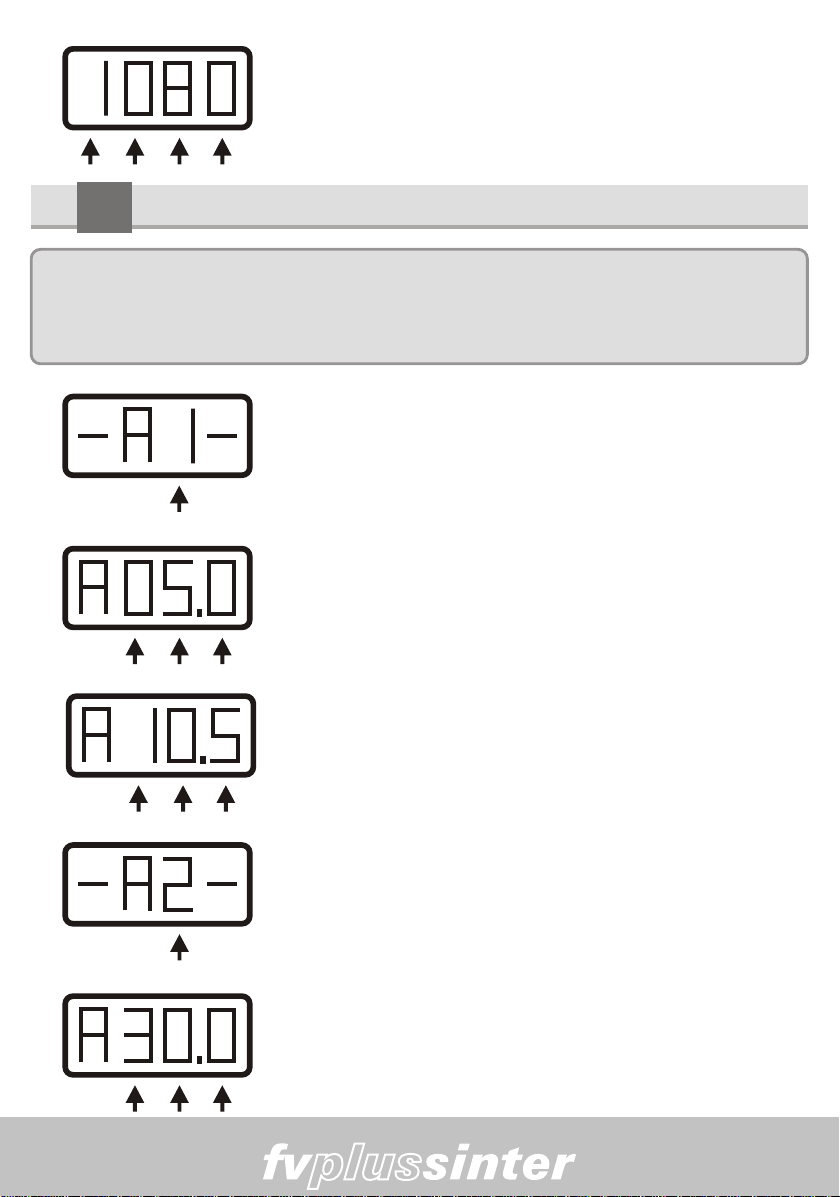
8-11) Next, activate the parameters adjustment keys
(09),oneforeachdigitshowingonthedisplaythedesired
valueforT2of1080ºC.
8.12 Adjusting The Heating Velocities. V1 E V2
Note: The heating speed V1 can assume values: minimum of 0.1ºC/min and
maximum of 20ºC/min.And he heating speed V2 can assume the minimum speed of
1ºC/minandmaximumof 70°C/min.
8-13) PROGRAMMING - V1 - Activating the V1 (12) key
themessage“-A1-“willshowonthedisplayforspeed1.
PROGRAME - T2
RECEITA - PADRÃO 8-14) Activating the parameters adjustment keys (09),
under“1”onthedisplayitwillshowtheheatingspeedthat
comes from the factory: “A05.0” (five degrees per
minute).
PROGRAME - VEL - 1 8-15) Activating on the parameters adjustment keys (09)
the keys which are under the display we can adjust the
speedforthedesiredvalueof10.5°c/min.
RAMPA - VELOC - 2 8-16) PROGRAMMING - V2 - Activating the V1 (12) key
twice the message “-A2-“ will show on the display for
speed2.
RECEITA - PADRÃO 8-17) Activatingon the parametersadjustment keys (09),
under “2” the display it will show the heating speed that
comes from the factory: “A30.0” (thirty degrees per
minute).
17

Manual
PROGRAME - VEL - 2 8-18) Activating on the parameters adjustment keys (09)
the keys which are under the display we can adjust the
speedforthedesiredvalueof35.0°C/min
8.19 Adjusting burn time (BASELINES)
Note: The burn times Pat-1 and Pat-2 for the sintering/infiltration processes start
in Hours. Ex: H1.15 corresponds to one hour and fifteen minutes. We remind you that
theminimumtimeallowedforPat-1andPat-2canbezeroEx.H0.00andthemaximum
timecanbeninehoursandfifty-nineminutes.Ex.H9.59.
8-20) Programming baseline 1. Activating the burning
time key (13) once, the display will shoe the message
“Pat.1”.
SELECIONE - PAT- 2
PROGRAME - PAT - 1
RECEITA - PADRÃO 8-21) Activating the parameters adjustment keys (09),
under “1” on the display it will show the time that comes
fromthefactoryforthestandardrecipe:“H0.15”.
8-22)Activatingtheparametersadjustmentkeys(09),we
can adjust the burn time to the desired value, “H0.10”,
thatis10minutes.
SELECIONE - PAT- 2 8-23) Programming baseline 2. Activating the burning
time key (13) twice, the display will shoe the message
“Pat.2”.
18

Manual
RECEITA - PADRÃO 8-24) Activating the parameters adjustment keys (09),
under “2” on the display it will show the time that comes
fromthefactoryfor thestandard recipe:“H0.30” thatis 30
minutes.
PROGRAME - PAT - 2 8-25)Activatingtheparametersadjustmentkeys(09),we
canadjusttheburntimetothedesiredvalue“H1.00”,that
is1hour.
8.26 ) Programming the muffle opening and closing
Themuffleclosingandopeningprocessescanbeprogrammedindependently.
FECHA / DESCE 8-27) Programming the muffle closing.Activating the key
(16)oncethedisplaywillshowthemessage“dES.0”.
FECHA / DESCE 8-28) Activating the parameters adjustment key (09)
below“0”wechoosethedesiredpositionaccordingtothe
table below. In this case, on the position “2” the piece
entry will take about 2 minutes to complete the piece
entry.
ABRE / SOBE 8-29) Activating the Open/Close (Abre/Fecha) key (16)
twice,thedisplaywillshowthemessage“Sob.d”.
ELEVADOR - SOBE 8-30) Activating the parameters adjustment key (09)
below“d”wechoosethedesiredpositionaccordingtothe
table below. In this case, on the position “1” the piece
entrywilltakeabout1minutetocompletethepieceexit.
19
Table of contents
Other EDG Furnace manuals


Popular Furnace manuals by other brands


Haier
Haier GE NF97UM Service manual

International comfort products
International comfort products NAHB00101MH installation instructions

Lennox
Lennox EL195DF SERIES user manual

Vogelzang International
Vogelzang International 1500 owner's manual

Weld Rite
Weld Rite Shaver Pro 140 Installation and operating instructions

Maytag
Maytag Amana AMVC80 manual

Aspen
Aspen AAN Series installation guide

Lennox
Lennox EL196DFE Series User's information manual

Rinnai
Rinnai RHFE-201FA OWNER'S OPERATION AND INSTALLATION MANUAL

Goodman
Goodman GMV95 Series installation instructions

Bryant
Bryant 4-WAY MULTIPOISE TWO-STAGE CONDENSING GAS FURNACE... Product data

Nortek
Nortek TA Series installation instructions