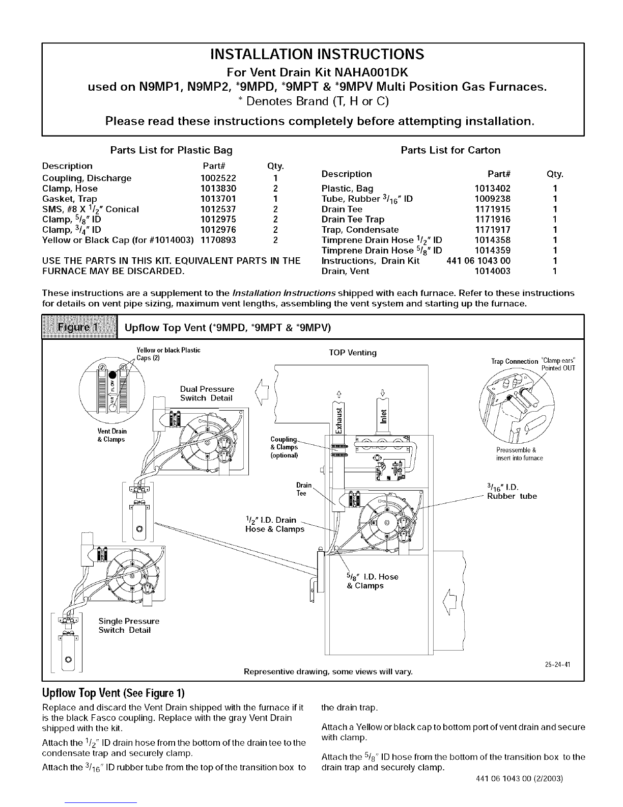
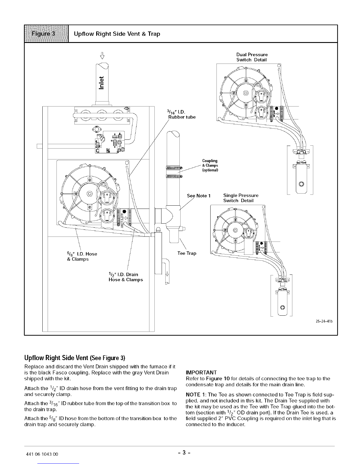
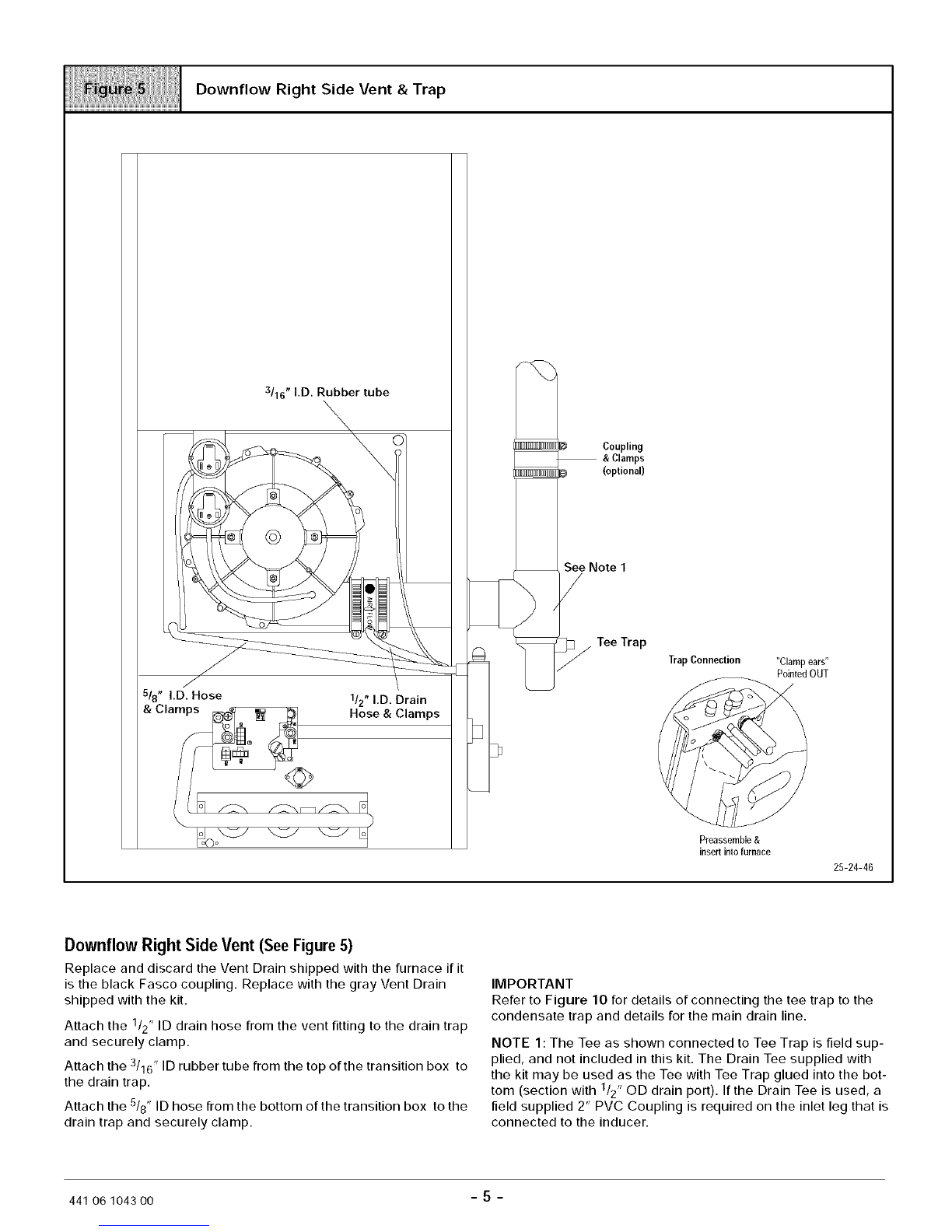
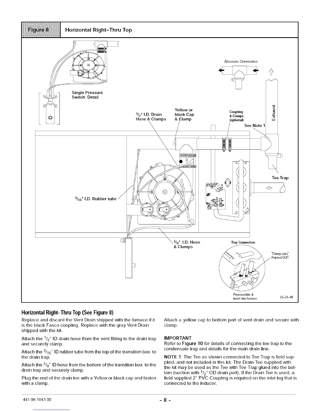
ICP N9MP2 Quick start guide
Other ICP Furnace manuals

ICP
ICP R92ESN User manual

ICP
ICP N8MPN User manual

ICP
ICP NTV6/NNE User manual

ICP
ICP H9MPT050F12B1 User manual

ICP
ICP NTP6/TNESeries User manual

ICP
ICP NTG9050FFA2 Installation instructions

ICP
ICP NOMF105D12A Quick start guide

ICP
ICP NDN5050BFA1 User manual

ICP
ICP N9MP1080F16A2 User manual

ICP
ICP F9MXT Quick start guide

ICP
ICP H9MPX Quick start guide

ICP
ICP 8MPL075F16B1 User manual

ICP
ICP N8MPN User manual

ICP
ICP G9MAC Series User manual

ICP
ICP OLR Series Assembly instructions

ICP
ICP fbf050b12a4 Installation instructions

ICP
ICP OLR105A12B Quick start guide

ICP
ICP H9MPT050F12B1 User manual

ICP
ICP Induced Combustion Gas Furnace Technical manual

ICP
ICP 8MPT Series Quick start guide


Popular Furnace manuals by other brands

Armstrong
Armstrong EG7H SERIES Installation and maintenance instructions

Payne
Payne PG92ESA Installation, start-up, operating and service and maintenance instructions

SUPREME
SUPREME FEM10-M2301CM-A Installation instructions and homeowner's manual

Ingersoll-Rand
Ingersoll-Rand S9V2B080D4VSAC/D Installer's guide

Johnson Controls
Johnson Controls TM9T User's information manual

Fluke
Fluke 9118A user manual

Lennox
Lennox EL195UHE Elite Series Unit information

Intertherm
Intertherm M7RL Series user manual

HDG
HDG Pelletmaster 15 Operation manual

Pinnacle
Pinnacle Aero Bella AB-716C-QH User's manual and operating instructions

Nortek
Nortek MG2S Series installation instructions

VERDER
VERDER CARBOLITE GERO ABF 8/28 Installation, operation and maintenance instructions

Goodman
Goodman GMV9 Installation & operating instructions

SUPREME
SUPREME SUP10-M2301C Installation instructions and homeowner's manual

Dettson
Dettson AMT400B34-SM1PMA Installation instructions and homeowner's manual

Evcon
Evcon DGD 60 MBH installation instructions

Trane
Trane S8B1A026M2PSAB Installer's guide

Hart Sceintific
Hart Sceintific 9113 user manual