Edlund Company 350 User manual

Please read thoroughly before operation and keep for future reference
1
M092 REV. C
PRODUCT MANUAL- M092
MODEL 350 & 350XL PRODUCE
SLICER
Please read thoroughly before operation and keep for future reference
2
M092 REV. C
SAFETY
WARNING: THE BLADES ARE VERY SHARP! BE SURE NOT TO TOUCH THE
CUTTING EDGE OF THE BLADES.
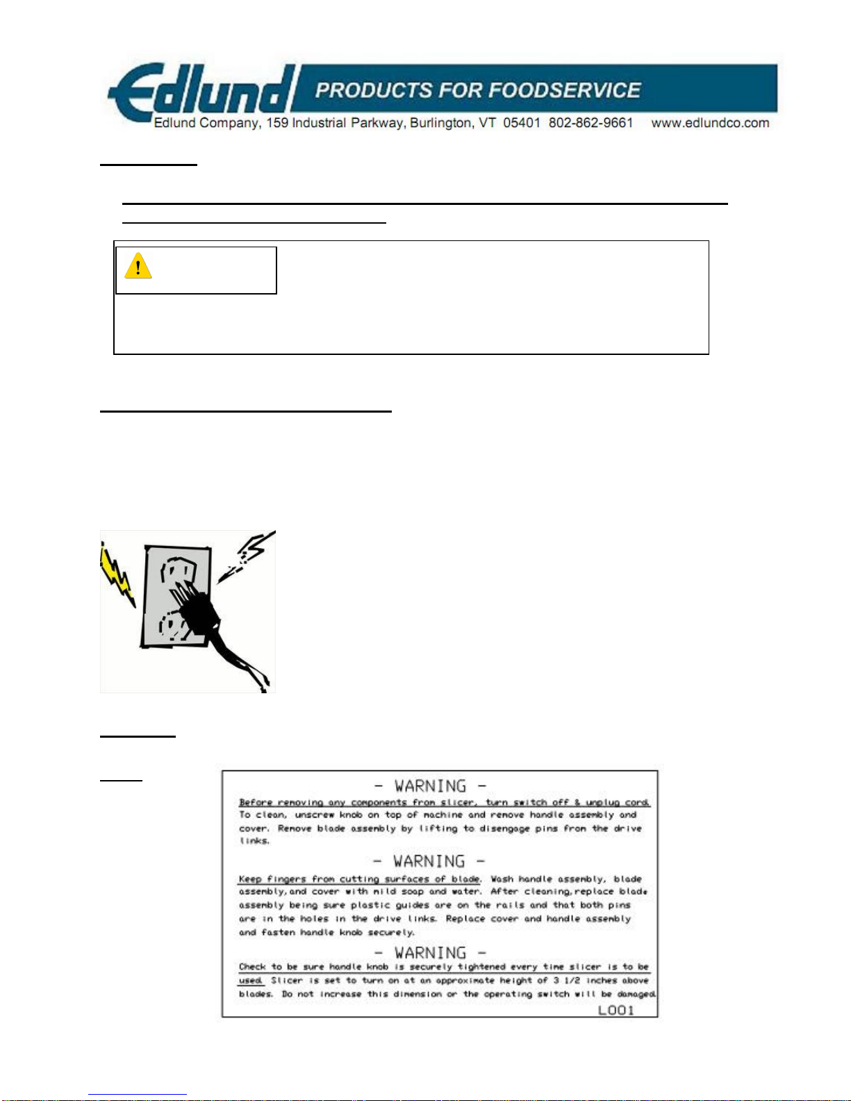
Grounding/Earthing Instructions
Slicer MUST be grounded. Grounding reduces risk of electric shock by providing an
escape wire for the electric current, if a electrical short occurs. This slicer is equipped
with a cord having a grounding wire with a grounding plug. The plug must be plugged
into an outlet that is properly installed and grounded.
LABELS
L001
To avoid risk of electrical shock, this slicer must be
grounded and plug must not be altered.
WARNING

Please read thoroughly before operation and keep for future reference
3
M092 REV. C
I. SPECIFICATIONS
MODEL NO. 350, 350XL
Power Requirement 115 volt, 1.5 Amp, 50-60 HZ
230 volt, 0.8 Amp, 50-60 HZ
Speed 600 – 750 RPM for drive cam assembly
Slice Thickness 3/16 inch, 1/4 inch, 3/8 inch standard slice thickness*
Size 350 12” W x 14-1/2” H x 18.5” D (305mm x 368mm x 470mm)
Size 350 XL 12” W x 14-1/2” H x 20” D (305mm x 368mm x 508mm)
Weight 350 19.1 lb. (8.7 kg)
Weight 350 XL 20.5 lb. (9.3 kg)
*Measured from center of blade to center of blade. There are other
sizes available upon request. Call factory or your dealer.
II. SLICER DESCRIPTION
The Model 350, 350XL electric produce slicer is designed to slice tomatoes,
oranges, peppers and other soft products into multiple slices with a single stroke. It
will slice produce up to 3-1/2 inches in diameter. The 350 slicer throat length is 4.25”,
while the 350 XL is 5.75”. The slicing of any hard, dense produce such as onions or
potatoes will void the warranty and will severely damage the blades and the pusher
fingers. The slicer is approved by the appropriate certifying organizations.
The slicer is manufactured of stainless steel and aluminum and it can be easily
disassembled for cleaning and/or maintenance.
NOTE: All slicers manufactured starting 2009 have the style pusher assembly
A1500 and use either the PI368 3/16”-3/8” Pusher Insert or PI014 1/4” Pusher
Insert. The insert is a plastic resin (lexan) design.

Please read thoroughly before operation and keep for future reference
4
M092 REV. C
III. Operating Instructions
CAUTION: WITH POWER SWITCH OFF, CHECK TO BE SURE THAT PUSHER
SECURING KNOB IS TIGHT AND PUSHER FINGERS ARE CENTERED
BETWEEN THE BLADES THE FIRST TIME SLICER IS USED AND AFTER
CLEANING OR MAINTENANCE. FOR PUSHER ASSEMBLY ALIGNMENT AND
ADJUSTING PROCEDURE, SEE PAGE 9.
To operate the slicer, plug the power cord into a grounded outlet with the same
voltage as listed on the legend plate located on the side of the motor cover. Lift the
pusher assembly so that it rotates about its hinge point and raise it until the pusher
arms are vertical. Turn the on and off switch, located on the side of the motor cover,
to the on position. The slicer motor should not start. Place a tomato or any other
soft product that is to be sliced in the center of the bank of blades of the blade carrier
assembly, with the product to be sliced orientated in the desired direction.
WARNING: THE BLADES ARE VERY SHARP! BE SURE NOT TO TOUCH THE
CUTTING EDGE OF THE BLADES.
1. Lower the pusher assembly toward the blades. The slicer motor will start
when the pusher reaches a pre-set distance
from the blades. Keep lowering the pusher
assembly until the pusher fingers contact the
product to be sliced and continue the
downward motion using a very light downward
force until the product is completely sliced.
(See Figure 1).
Lift the pusher assembly to its original
position. The slicer motor will stop and
another product can be placed on the blades
and the slicing process can be repeated.
The pre-set activation distance can be adjusted by loosening the thumb screw,
on the side of the pusher head, and rotating the metal cam. Retighten thumb
screw once desired activation height is achieved.
WARNING: NEVER FORCE PUSHER ASSEMBLY DOWN. USE A LIGHT
DOWNWARD PRESSURE ONLY OR BLADES AND PUSHER FINGERS WILL
BECOME DAMAGED.
Figure 1

Please read thoroughly before operation and keep for future reference
5
M092 REV. C
IV. Cleaning and Maintenance Instructions
WARNING: NEVER CLEAN OR MAINTAIN THE ELECTRIC SLICER WITHOUT
TURNING THE ON AND OFF SWITCH TO THE OFF POSITION AND
UNPLUGGING POWER CORD FROM POWER SOURCE.
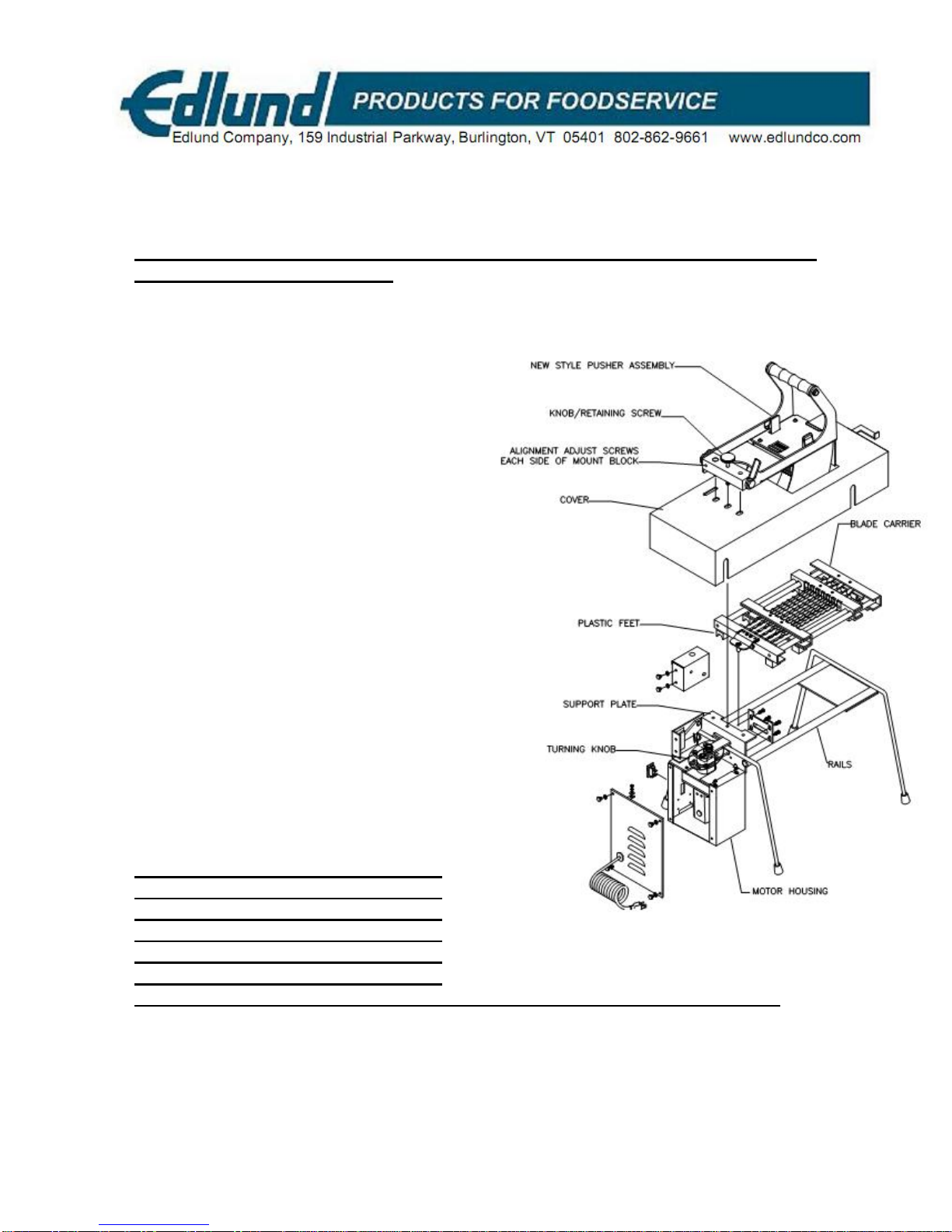
1. The pusher assembly, cover and blade carrier
assembly is easily removed for cleaning. In order to
remove these items, loosen the pusher assembly
retaining screw and lift the pusher assembly off the
unit. Remove the cover and remove the blade
carrier assembly by first turning the cam assembly
until the top pin is towards the front of the slicer.
(See Figure 2.)
2.Lift the blade carrier off the unit.
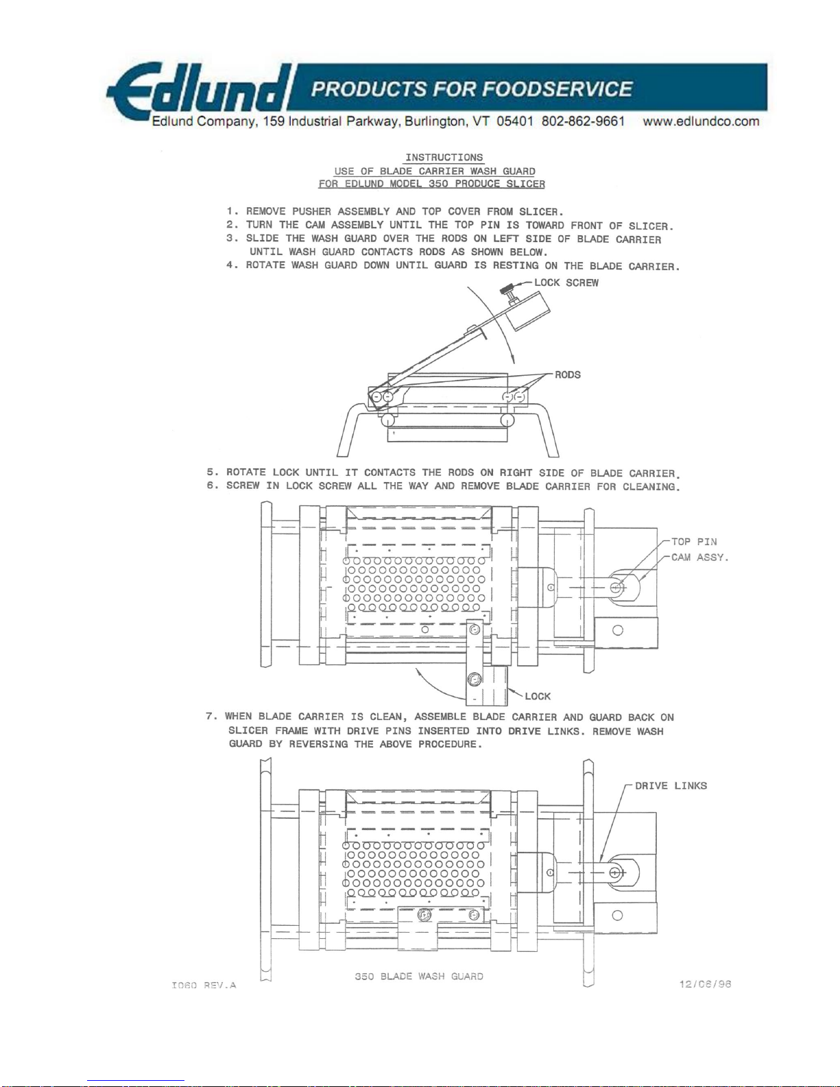
3. IMPORTANT: To avoid injury, blade carrier
should be stored and washed sharp side down in
provided wash/storage guide. If you do not have
this guide one should be ordered as Edlund part
#A350 (A350L for XL version).
4. For the Pusher Assembly, follow the disassembly procedure below for cleaning
parts, replacing a damaged pusher insert or changing slice size.
CAUTION: ALWAYS MATCH BLADE SIZE TO PUSHER INSERT SIZE. DAMAGE TO
BLADES, AND OR PUSHER FINGERS CAN OCCUR IF INCORRECTLY MATCHED.
A) Open Pusher Assembly to full open position using handle. The Pusher Open
Stop should be resting on cover as seen in figure 3 below.
B) Squeeze Insert Tabs in toward each other to release Insert. Pull Insert
straight out away from Pusher. See figure 4.
C) Slide Guard GR011 up approx. ½” then lift Guard straight out away from
Pusher Frame. See figure 5.
FIGURE #2

Please read thoroughly before operation and keep for future reference
6
M092 REV. C
WARNING: THE BLADES ARE VERY SHARP! BE SURE NOT TO TOUCH THE
CUTTING SURFACE OF THE BLADES.
Please read thoroughly before operation and keep for future reference
7
M092 REV. C
Wash the pusher assembly, the cover and the blade carrier assembly in mild soap
and water or in a dishwasher. The rest of the slicer can be wiped off using a damp
cloth.
WARNING: NEVER SUBMERGE OR PLACE ENTIRE ELECTRIC SLICER OR
MOTOR HOUSING IN WATER.
1. To assemble equipment after
cleaning, turn the cam assembly until
the top pin is toward the front of the
slicer and install the blade carrier in
place, making sure that plastic feet
are on the rails and that the drive
mount pins are engaged in the holes
of the drive links. Slide the cover in
place and line up the holes in the
cover with holes in the support plate.
Also make sure that the cover
interlock pin, located on the inside of
the cover, is aligned with the hole in
the interlock switch bracket. Install
the pusher assembly in place by
inserting the pins of the pusher mount
through the holes in the cover into the
holes in the support place. Start the
pusher retaining screw and leave the
screw loose. Lower the pusher
assembly until the pusher fingers
engage the space between the
blades, center the cover and tighten
the pusher retaining screw. (See
Figure 6)
WARNING: MAKE SURE THE
PUSHER FINGERS DO NOT
CONTACT THE BLADES. BLADES
AND PUSHER FINGERS WILL BE
DAMAGED IF SLICER MOTOR IS
STARTED WITH THE PUSHER
FINGERS IN CONTACT WITH THE BLADES OR USED WHEN MISALIGNED.
2. The set of blades can be replaced if the blades become dull. It is recommended
that all the blades be replaced at the same time because they may stretch during
use, and replacement of only a few blades may cause the old blades to be loose
when the blade-holders are tightened.
Figure 6

Please read thoroughly before operation and keep for future reference
8
M092 REV. C
3. The set of blades must be kept tight in order to function properly. Check the
blade tension of all the blades by turning the blade carrier assembly over with the
blade-cutting surface down. Run your fingers across the back of the set of
blades, one at a time, the blades should "ring" and have a similar sound. If any of
the blades appear to have a dull sound, contact your authorized service station.
NOTE: If for any reason the Model 350, 350XL Slicer does not function properly,
consult the trouble-shooting guide for assistance or call the factory or your local
service center.
WARRANTIES: The Edlund Company warrants these products to be free from
defects in material and workmanship for a period of one year from date of
purchase. The company's obligation under this warranty is limited to repairing
or replacing without charge any part or parts found to be defective under
normal use. It is the responsibility of the purchaser to return the entire unit to
the factory or a factory service branch, transportation charges prepaid. This
warranty does not cover parts that must be replaced under normal use,
including knives and drive gears on can openers. The company authorizes no
other warranty, written or verbal. Carrier is responsible for merchandise in
transit to you.
NEW BLADES SHOULD BE REPLACED BY EDLUND.
Please read thoroughly before operation and keep for future reference
9
M092 REV. C
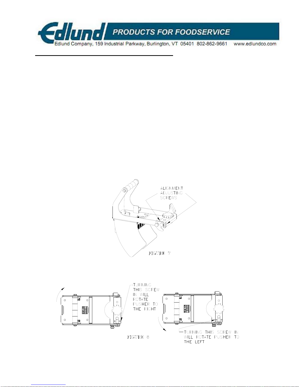
Pusher Assembly Alignment Check and Procedure
1. With the unit unplugged and the ON/OFF switch in the OFF position and the
pusher assembly mounted to the unit check the alignment of the pusher
fingers to the blades. The pusher fingers should be centered in the spaces
between the blades. If they are not follow step 2 below.
2. Locate the alignment adjusting screws shown in figure 7. Determine which
direction the pusher should rotate by observing where the pusher fingers align
in between the blades. Using a small standard screwdriver you can turn the
appropriate screw to rotate the pusher left or right. When adjusting a screw
inward the opposing screw must be turned outward or loosened first. Center
the pusher fingers and tighten the opposing screw. See figure 8 below. Check
alignment again after tightening and adjust again if needed.
NOTE: Proper alignment is critical to the functioning of the slicer and will help
ensure longevity of blades and pusher inserts. If blades or pusher assembly is
changed perform an alignment before use.

Please read thoroughly before operation and keep for future reference
10
M092 REV. C
Pusher Assembly Actuator Cam AC002 Adjustment
The Pusher Assembly includes an easy adjustment for the triggering of the slicer blades
to start operating. This can be adjusted for a particular size of food product you are
slicing by having the slicing blades start operating earlier or later as the pusher is
lowered down to slice food product. Adjustment does not require the use of any tools. A
knurl screw has been provided for this and can be loosened and tightened by hand. The
knurl screw is also captivated on the pusher assembly to avoid accidental loss. To
adjust the actuator cam follow the procedure below. Proper adjustment of the actuator
cam helps ensure that the pusher fingers are in contact with the food product before the
blades start operating. When adjusted properly the food product will be held firmly while
being sliced providing the best slice possible. Follow procedure below and see Figure 9.
1. With the unit unplugged and the ON/OFF switch in the OFF position and the
pusher assembly mounted to the unit you can begin to make the actuator cam
adjustment. To adjust for slicing larger food product loosen the knurl screw by
hand and rotate the actuator cam AC002 down as needed. This will cause the
slicing blades to start operating sooner as the pusher is lowered onto the food
product. This also captures the larger food product properly between the pusher
insert fingers and blades. You can hear the actuator switch engage by listening
for the “click” sound as the pusher is lowered.
2. To adjust for slicing smaller food product loosen the knurl screw by hand and
rotate the actuator cam AC002 up as needed. This will cause the slicing blades
to start operating later as the pusher is lowered onto the food product. This also
captures the smaller food product properly between the pusher insert fingers and
blades. You can hear the actuator switch engage by listening for the “click” sound
as the pusher is lowered.
Please read thoroughly before operation and keep for future reference
11
M092 REV. C

Please read thoroughly before operation and keep for future reference
12
M092 REV. C
Trouble Shooting Guide
Problem Cause Correction
1. Not plugged into outlet. 1. Plug cord set into grounded outlet with the
same voltage as listed on the rating plate
located on the side of the motor housing.
2. Cover actuating switch
inoperative. 2. Replace leaf switch (S627) or contact dealer
/service center.
3. Switch actuator cam not
contacting roller switch bracket. 3. Adjust pusher head cam assembly (AC002).
See page “Pusher Assembly cam adjustment”
for procedure. If unit fails to energize, replace
roller switch (S626) or contact dealer /service
center.
4. On-off switch not turned on or
inoperative. 4. Contact dealer or service center.
5. Broken wire or loose terminals. 5. Contact dealer or service center.
7. Broken wire in cord set. 7. Contact dealer or service center.
6. Circuit breaker tripped. 6. Reset circuit breaker (B116) and if breaker
trips, call dealer or service center.
9. Motor failed 9. Call dealer or service center.
I. Slicer will not start.
10. No current flow through line
filter on 230-volt slicer. 10. Replace filter (F088) or call dealer/service
center.
1. Blade assembly not on guide
rails. 1. Call dealer or service center.
2. Bent or damaged pusher fingers
(old style P144) or ( new style
PI368, PI014 plastic inserts)
2. Straighten or replace pusher fingers. For new
style replace proper plastic pusher insert and
align to blades before use. See page “New Style
Pusher Assembly” for procedure.
3. Pusher mounting flange of motor
mount is bent. 3. Straighten flange or replace frame assembly
(A650/A651).
4. Loose rivet (R048). 4. Check rivets and bushings and replace as
required.
II. Pusher fingers contact
blades or pusher fingers
not centralized between
blades.
5. Pusher head misaligned 5. See page “New Style Pusher Alignment” for
procedure.
1. Worn drive link guide support. 1. Replace support ((S210).III. Blade assembly will
not stay on rails. 2. Motor mounting plate bent down. 2. Remove cover and motor and straighten
plates to be parallel to rails within (0.015) total
indicated reading.
1. Blade holder retaining screws
(S049) not tightened to correct
torque.
1. Consult assembly procedure for proper
torque of screws.
2. Holes in blades are elongated. 2. Check blades and replace as required and
torque according to assembly procedure.
IV. Blades loose on blade
carrier.
3. Some of blades on blade carrier
may have been replaced with new
blades.
3. Tighten blade holder retaining screws (S049)
to correct torque. Turn blade carrier over and
check tightness of each blade by "strumming"
back of blades. If blade or blades have dull
sound, replace and retighten to torque outlined
in assembly procedure.
Please read thoroughly before operation and keep for future reference
13
M092 REV. C
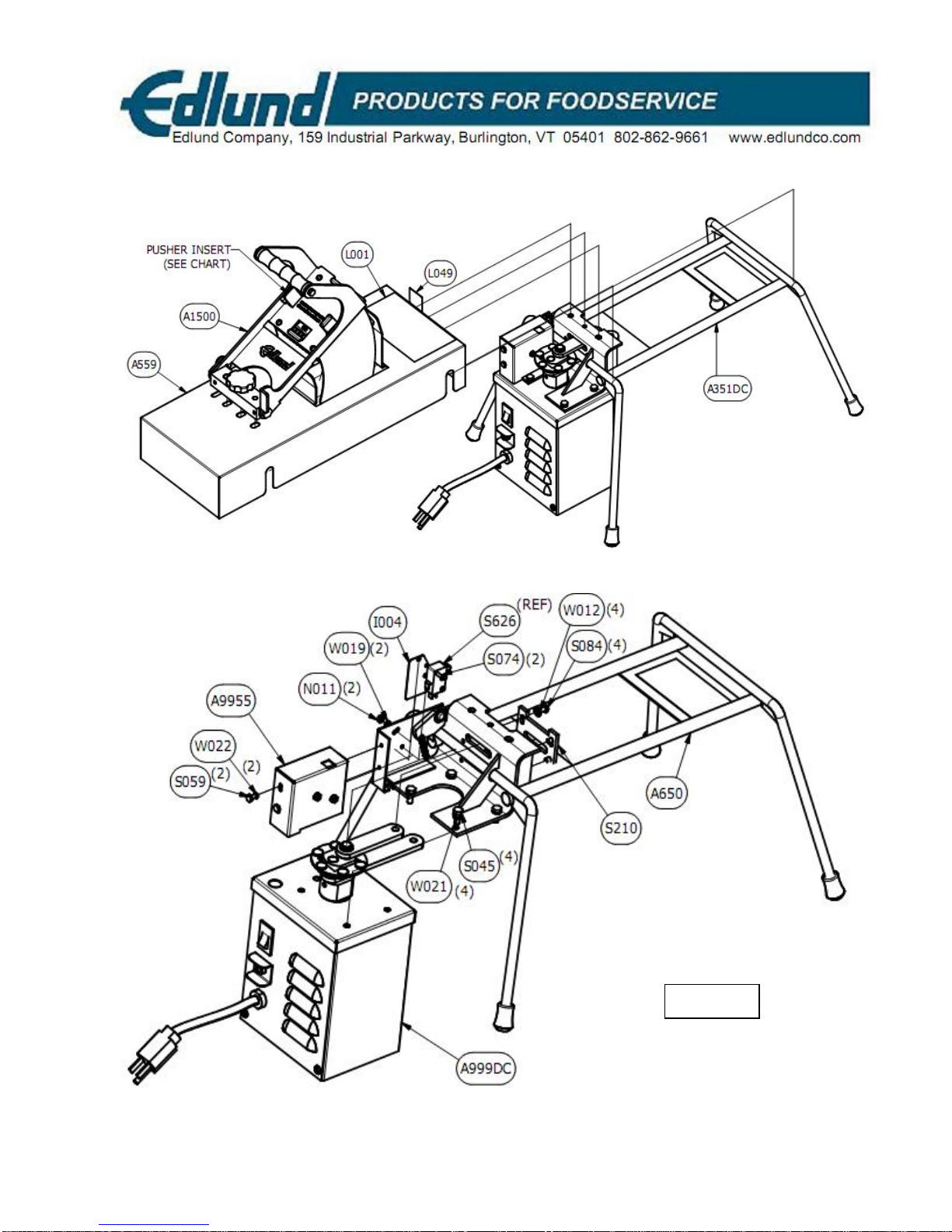
350 SLICER—115V
A351DC

Please read thoroughly before operation and keep for future reference
14
M092 REV. C
350 SLICER ASSEMBLY AND PARTS LIST—115V
QTY PART
NUMBER DESCRIPTION
1A1500 ASSEMBLY, PUSHER HEAD W/ REMOVABLE INSERT
1A351DC ASSEMBLY, 350 MOTOR & FRAME
1A559 WELDMENT, COVER 350
1L001 LABEL, WARNING
1L049 LABEL, NSF MARK
350 FRAME ASSEMBLY (A351DC)—115V
QTY PART
NUMBER DESCRIPTION
1A650 ASSEMBLY, 350 FRAME
1A9955 ASSEMBLY, LEAF MICRO SWITCH AND COVER
1A999DC ASSEMBLY, HOUSING, MOTOR & GEARBOX+LINKAGE,
115V
1I004 INSULATOR, SWITCH PAD
2N011 NUT, #4-40 BRASS
4S045 SCREW, #10-32 X 1/2, HEX HD CAP, SS
2S059 SCREW, #6-32 X 1/4 HEX HEAD, SS
2S074 SCREW, #4-40 x 5/8, SLOTTED, BRASS
4S084 SCREW, #8-32 X 5/16 S/S RHM, SLOTTED
1S210 SUPPORT, LINK GUIDANCE
1S626 SWITCH, ROLLER
4W012 WASHER, FLAT, #8 SS
2W019 WASHER, #4 INTRL TOOTH LOCK, SS
4W021 WASHER,#10 LOCK, SS
2 W022 WASHER,#6 LOCK, SS
350 PUSHER/BLADE
ASSEMBLY
BLADE
ASSEMBL
YPUSHER
INSERT SIZE
A553 PI368 3/16
A554 PI014 1/4
A567 PI368 3/8
Please read thoroughly before operation and keep for future reference
15
M092 REV. C
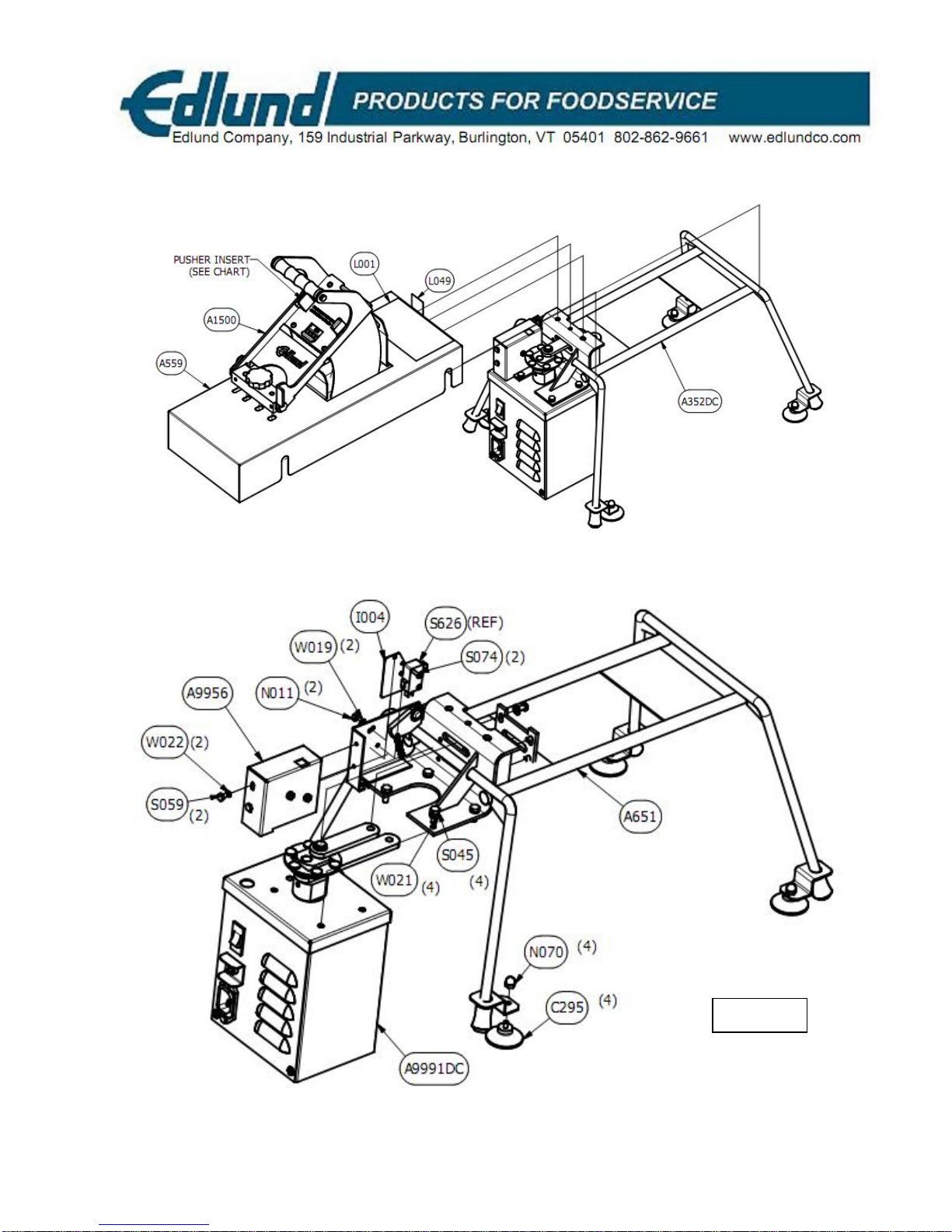
350 SLICER—230V
A352DC

Please read thoroughly before operation and keep for future reference
16
M092 REV. C
350 SLICER ASSEMBLY AND PARTS LIST—230V
QTY PART NUMBER DESCRIPTION
1A1500 ASSEMBLY, PUSHER HEAD W/ REMOVABLE
INSERT
1A352DC ASSEMBLY, 350 W/230V MOTOR
1A559 WELDMENT, COVER 350
1L001 LABEL, WARNING
1L049 LABEL, NSF MARK
350 FRAME ASSEMBLY (A352DC)—230V
QTY PART NUMBER DESCRIPTION
1A651 ASSEMBLY, 350 FRAME W/ SUCTION CUPS
1A9956 ASSEMBLY, MICRO SWITCH AND COVER, 230V
1A9991DC ASSEMBLY, 350 MOTOR/GEARBOX, 230V
4C295 CUP, RUBBER SUCTION
1I004 INSULATOR, SWITCH PAD
2N011 NUT, #4-40 BRASS
4N070 NUT, #8-32 NYLON ACORN HEX
4S045 SCREW, #10-32 X 1/2, HEX HD CAP, SS
2S059 SCREW, #6-32 X 1/4 HEX HEAD,SS
2S074 SCREW, #4-40 x 5/8, SLOTTED, BRASS
4S084 SCREW, #8-32 X 5/16 RHM, SLOTTED, SS
1S210 SUPPORT, LINK GUIDANCE
1S626 SWITCH, ROLLER
4W012 WASHER, FLAT, #8 SS
2W019 WASHER, #4 INTRL TOOTH LOCK, SS
4W021 WASHER,#10 LOCK, SS
2W022 WASHER,#6 LOCK, SS
Please read thoroughly before operation and keep for future reference
17
M092 REV. C
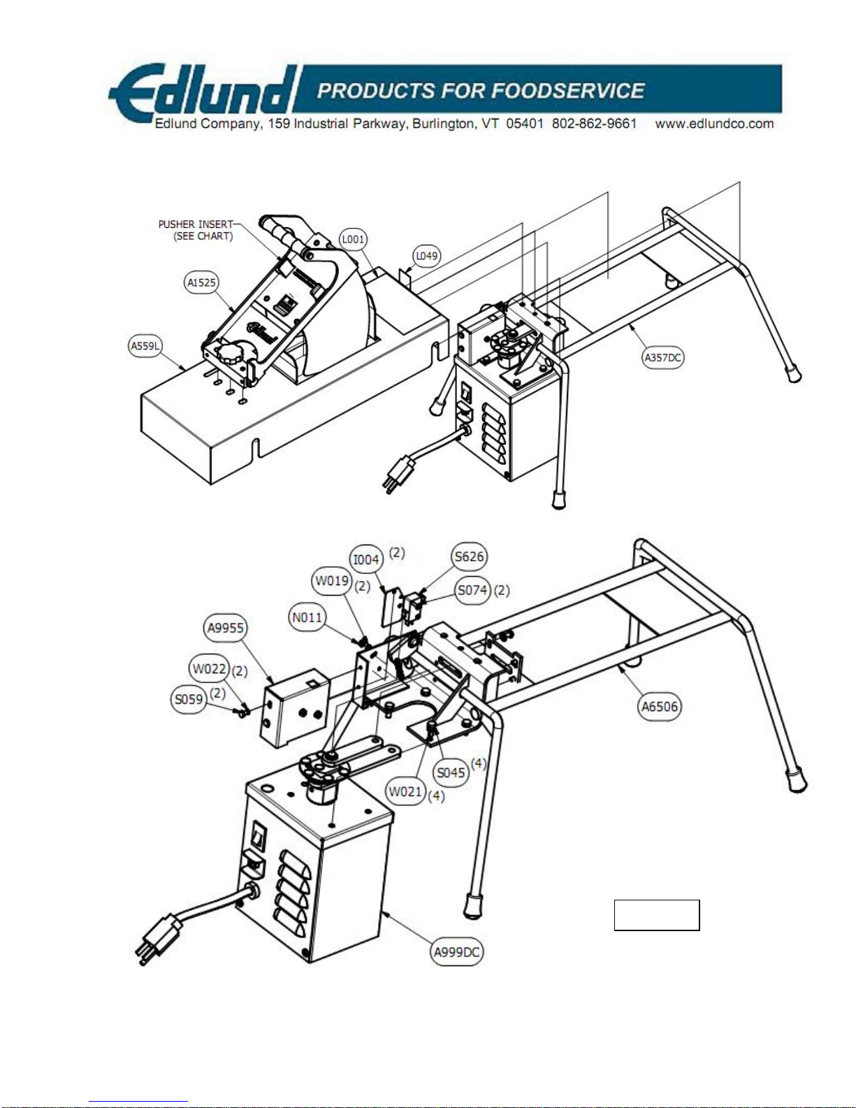
350XL SLICER—115V
A357DC

Please read thoroughly before operation and keep for future reference
18
M092 REV. C
350XL SLICER ASSEMBLY AND PARTS LIST—115V
QTY PART NUMBER DESCRIPTION
1A1525 ASSEMBLY, PUSHER HEAD W/ REMOVABLE INSERT,
350XL
1A357DC ASSEMBLY, 350XL MOTOR/FRAME, 115v
1A559L WELDMENT, COVER, 350XL
1L001 LABEL, WARNING
1L049 LABEL, NSF MARK
350XL FRAME ASSEMBLY (A357DC)—115V
QTY PART NUMBER DESCRIPTION
1A6506 ASSEMBLY, FRAME, 350XL
1A9955 ASSEMBLY, LEAF MICRO SWITCH AND COVER
1A999DC ASSEMBLY, HOUSING, MOTOR & GEARBOX+LINKAGE,
115V
1I004 INSULATOR, SWITCH PAD
2N011 NUT, #4-40 BRASS
4S045 SCREW, #10-32 X 1/2, HEX HD CAP, SS
2S059 SCREW, #6-32 X 1/4 HEX HEAD,SS
2S074 SCREW, #4-40 x 5/8, SLOTTED, BRASS
4S084 SCREW, #8-32 X 5/16 RHM, SLOTTED, SS
1S210 SUPPORT, LINK GUIDANCE
1S626 SWITCH, ROLLER
4W012 WASHER, FLAT, #8 SS
2W019 WASHER, #4 INTRL TOOTH LOCK, SS
4W021 WASHER,#10 LOCK, SS
2W022 WASHER,#6 LOCK, SS
350XL PUSHER/BLADE
ASSEMBLY
BLADE
ASSEMBL
YPUSHER
INSERT SIZE
A553L PI368 3/16
A554L PI014 1/4
A567L PI368 3/8
Please read thoroughly before operation and keep for future reference
19
M092 REV. C
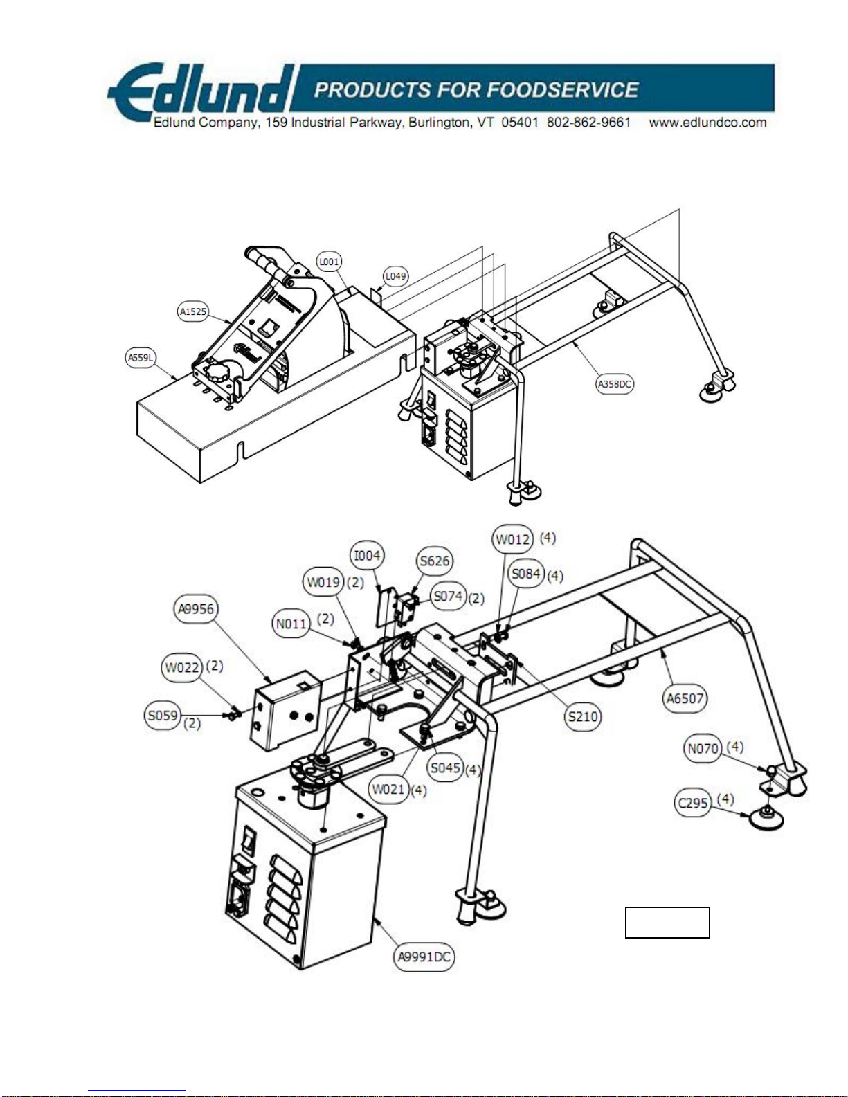
350XL SLICER—230V
A358DC

Please read thoroughly before operation and keep for future reference
20
M092 REV. C
350XL SLICER ASSEMBLY AND PARTS LIST—115V
QTY PART NUMBER DESCRIPTION
1A1525 ASSEMBLY, PUSHER HEAD W/ REMOVABLE INSERT,
350XL
1A358DC ASSEMBLY, 350XL MOTOR/FRAME, 230V MOTOR
1A559L WELDMENT, COVER, 350XL
1L001 LABEL, WARNING
1L049 LABEL, NSF MARK
350XL FRAME ASSEMBLY (A358DC)—230V
QTY PART NUMBER DESCRIPTION
1A6507 ASSEMBLY, 350XL FRAME W/SUCTION CUPS
1A9956 ASSEMBLY, MICRO SWITCH AND COVER, 230V
1A9991DC ASSEMBLY, HOUSING, MOTOR &
GEARBOX+LINKAGE, 230V
4C295 CUP, RUBBER SUCTION
1I004 INSULATOR, SWITCH PAD
2N011 NUT, #4-40 BRASS
4N070 NUT, #8-32 NYLON ACORN HEX
4S045 SCREW, #10-32 X 1/2, HEX HD CAP, SS
2S059 SCREW, #6-32 X 1/4 HEX HEAD,SS
2S074 SCREW, #4-40 x 5/8, SLOTTED, BRASS
4S084 SCREW, #8-32 X 5/16 RHM, SLOTTED, SS
1S210 SUPPORT, LINK GUIDANCE
1S626 SWITCH, ROLLER
4W012 WASHER, FLAT, #8 SS
2W019 WASHER, #4 INTRL TOOTH LOCK, SS
4W021 WASHER,#10 LOCK, SS
2W022 WASHER,#6 LOCK, SS
This manual suits for next models
1
Table of contents


