EDT EX-RAY User manual

EX-RAY
VOLTAGE
USER’s MANUAL
SPEED | DISTANCE | TEMP | CLOCK | BATT VOLTAGE
“An Aftermarket solution
for Electric Vehicles used
on-road or off-road”
Digital Speedometer Panel With Voltage
Meter for Golf Carts, NEV, Conversions

Normal Mode:
= Activate backlight manually
= Switch between screens in normal mode
= Start or stop the stop watch
Data Setting Mode:
= Enter data setting mode
= Switch between screens in data setting mode
= Scroll through current data setting
= Move to next digit of current data setting
Data Reset:
= Reset single-ride data
Adjustable Trip Distance Edit:
= Enter/exit adjustable trip distance edit mode
= Scroll distance value
Rally Mode:
= Enter/exit rally mode
= Scroll distance value
Lap Timer Mode:
= Enter/exit lap timer mode
= Clear lap timer data
= Start/stop lap timer
= Signal new lap
= Enter/exit lap data review mode
= Scroll through lap information
Short Cuts
2

3
Table Of Contents
2 Short Cuts (Quick Set up guide)
3 Table Of Contents
4 Welcome to EDT llc
> Enter Dealer and warranty purchase information
5 Precautions
6 Specications
8 Overview
11 Installation
12 Parts Breakdown
13 Universal Bracket - Steering Column Mount
15 CNC Bracket - Steering Column Mount
18 Temp Sensor Mount
22 General Speed 10mm BOLT Sensor Installation
25-Short hub Mag, 28-31 Short-long axle,
32-Jakes Disc Brake, 34-ClubCar Lift
36 Speed TAB Sensor ClubCar XRT Installation
38 Power Cable Installation
39 Steering Column Wire Protector
40 Wheel Size Calculator
43 Data Setting Mode
> MPH/KPH, Temp limits, Time, DC Voltage
warnings, Maintenance,
52 Normal Screen Modes
> Screen 1-2-3, Sleep Mode, Reset data screens
54 EX-RAY Features
> Explanations of all screen data, settings, functions
63 Troubleshooting / FAQ’s
65 Inch to Metric Tire Size Conversion Chart
66 Glossary
68 EX-RAY Model Numbers, Kits, Replacement Parts
70 EX-RAY USER Setup notes and battery change dates
72 Warranty Statement

Thank you for purchasing an EDT.llc Product:
The EX-RAY™ is Digital Speedometer Display, the EX-RAY™
product line provides valuable information about your vehicle
for your gas or electric golf car or modied buggy, Neighbor-
hood Electric vehicle (NEV), or Small Task Oriented Vehicle.
Please read this manual carefully before installing your
EX-RAY™ Display. Note: This Manual intended as guide to
proper installation but cannot predict every possible applica-
tion. Some modications may be required.
EX-RAY™ is a trademark of the Energy Design Tek LLC
Company Oregon USA
Please Record Important Information:
For future reference and customer support, please record the
following information:
PURCHASE DATE: ______________________________
DEALER: ______________________________________
DEALER PHONE: _______________________________
EX-RAY MODEL (ON BOX): _______________________
Keep this manual, sales receipt, and original box for future
use. Serial Number TAG and WARRANTY last pages.
SAVE THESE INSTRUCTIONS
4
Welcome to EDT-Exray
Copyright ©2013

WARNING:
When using the EX-RAY™
follow basic precautions,
including the following:
• Read all instructions be-
fore using the EX-RAY™
• When installing the DC
Motor temperature Sensor,
be careful removing the
bolt and not to damage the
motors internal eld coil.
EDT llc is not responsible
for damage done during this
process.
• Use EX-RAY™ only for its
intended purpose.
• To reduce rick or injury, do
not disassemble EX-RAY™
or its accessories.
• EX-RAY™ can be used
in the rain but should not be
used under water.
• Do not leave the main unit
in direct sunlight when not
being used.
• Check magnetic sensor
gap and magnet mounting
periodically.
• Do not bend, twist, kink, or
otherwise abuse the sensor
cables. A damaged cable
may produce incorrect read-
ings.
• When installing EX-RAY™,
turn the vehicle power off
(or ignition switch off); the
wires carry power from the
vehicles battery.
• Avoid contact with gaso-
line, de-greasers or other
chemical cleaners as they
may damage the EX-RAY™.
• Do not exceed 60VDC at
any time as this may dam-
age the EX-RAY™.
Precautions
5
Copyright ©2013

Specications
6
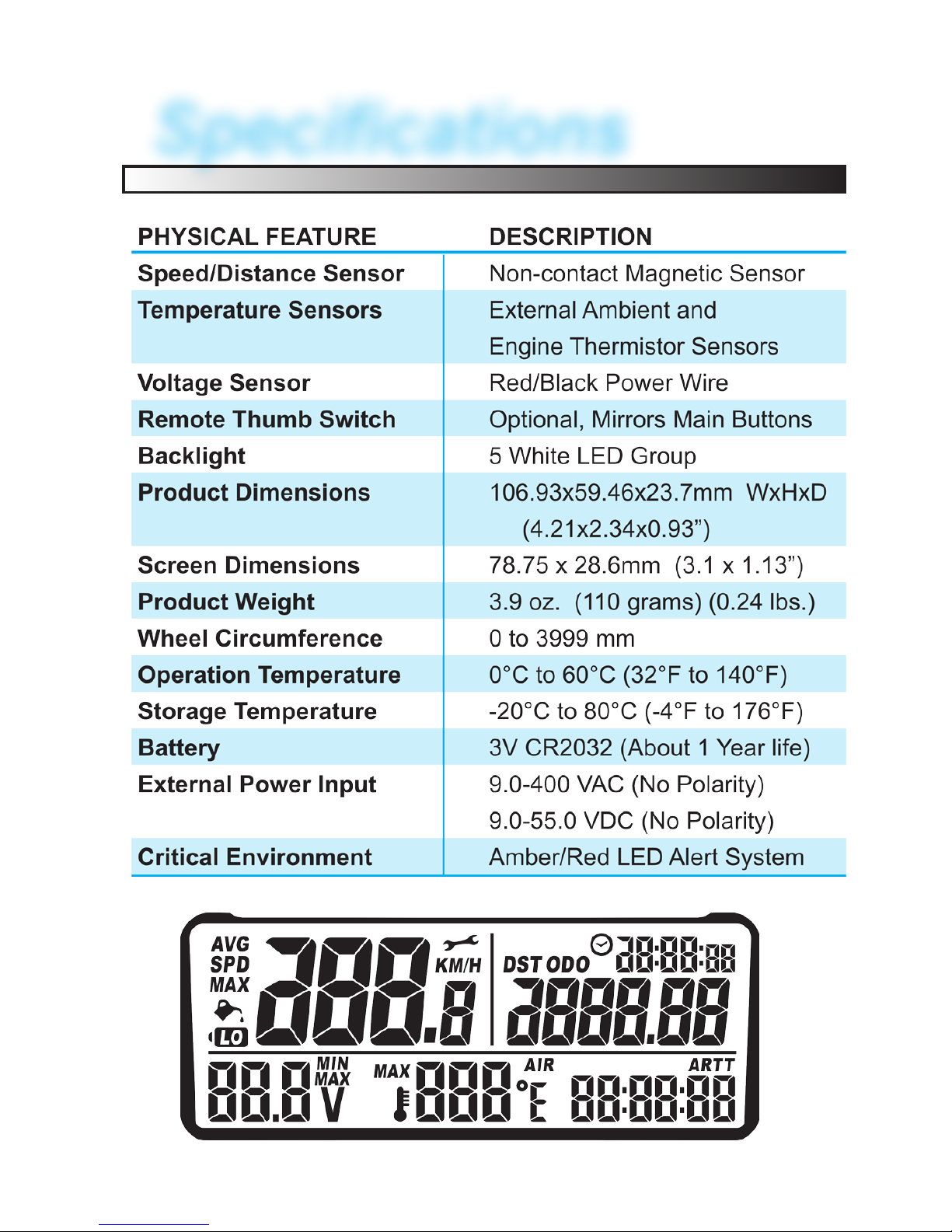
7
Specications

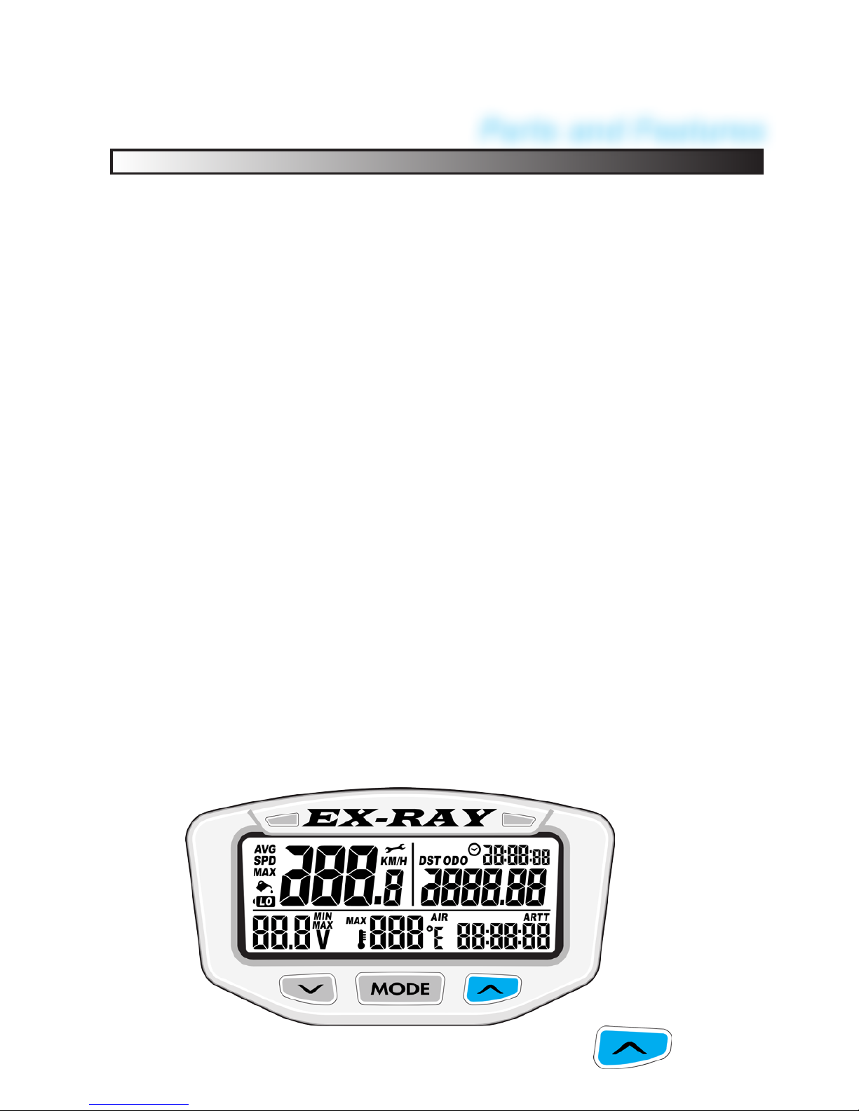
Overview
EX-RAY
™ Digital Speedometer:
Main Display:
• The display panel includes 3-user buttons, 2-warning
LED’s, and the LCD screen.
LED’s:
• Amber LED: Lights for temperature warning alert
(SOLID), Battery LOW Warning (FLASH).
• Red LED: Lights for over-temperature alert (SOLID)
and Battery LOW DANGER (FLASH).
Remote Switch (optional):
• The optional remote switch (sold separately) may be
required when access to the display buttons is not pos-
sible. Contact EDT llc for more information. (This is not a
standard option and special order only)
8
UP
MODE
DOWN
Small arrow
faces UP
Remote
Switch
Amber
LED
Red
LED
LCD
Screen
DOWN Left
Button
UP Right
Button
MODE Center
Button
Parts and Features
9
TO ACTIVATE BACKLIGHT MANUALLY PRESS
Display Backlight:
EX-RAY is equipped with a backlight for easy viewing during
night time operation.
Using External 12V Power:
• Display Backlight will light up with all ve backlight LED’s
• EX-RAY will remain lit as long as it senses wheel move-
ment. After 20 minute of inactivity, EX-RAY shuts off
the backlight. Press any button, roll the wheels, turn on
key switch (electric golf cars) or start the engine (gas golf
cars) and EX-RAY will light up again
• Amber and Red LED’s enabled (Shift or temperature)
Using Internal Batteries Only:
• EX-RAY will only stay lit for 3 seconds
• EX-RAY backlight will light up with 10% power to conserve
the internal battery power.
• If the LO symbol is present, the backlight will not turn
on. The LO symbol appears when battery voltage drops
below 2.45V
• If ambient temperature is cold (below -5°C, 23°F) the
backlight will not turn on.
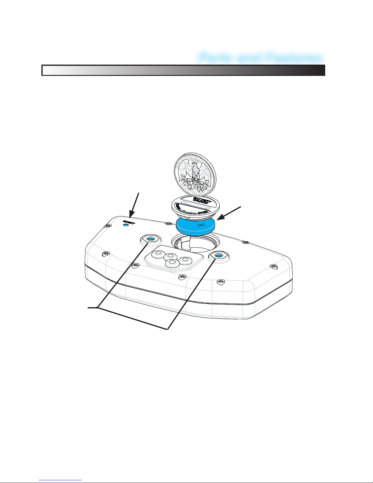
Battery
Reset
4mm
Mounting
Holes
Reset Button:
Use the Reset Button to erase data form the current ride includ-
ing clock and trip distance. Reset may also be required when
ever UNPLUGGING A SENSOR. (Forced computer to re-read
the sensor )
Internal Battery:
• EX-RAY has an internal non-rechargeable Lithium watch
type battery (#CR2032). The computer can be run from the
internal battery without external connection to vehicle power
source.
• To change the battery, unscrew the battery cap on the back oft
he computer with a coin. Make sure the POSITIVE SIDE of
the battery is FACING UP when replaced.
• REPLACE WITH BATTERY MODEL NUMBER CR2032
10
Parts and Features

Installation
11
Unpacking the Display:
Carefully remove the display from the packaging and verify all
the parts are included for your application.
Carefully remove the EX-RAY
cardboard TRAY from the box.
Be careful not to damage the rear
mounted connectors.
A sheet included will list the com-
ponents included in this kit.
Remove the bottom separator
and remove the display mounting
bracket (CNC Bracket Shown,
your application may vary). Color
options also available.
12
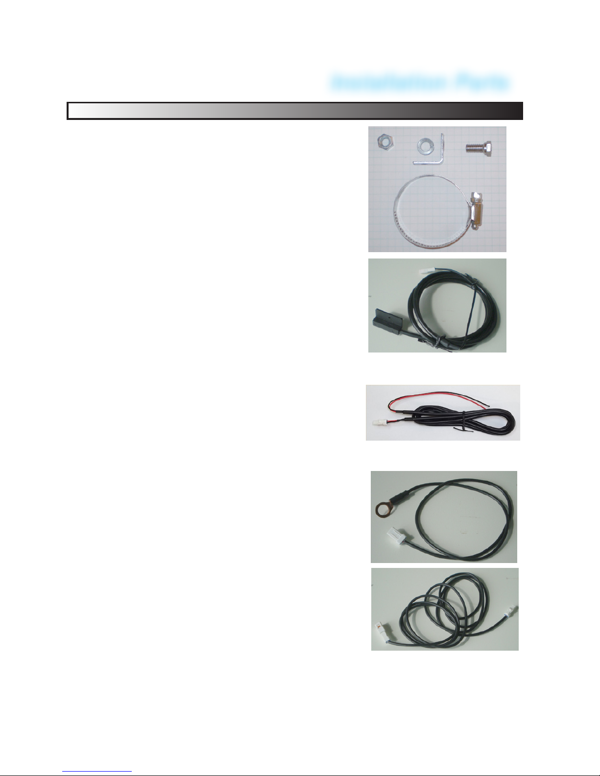
PARTS BREAKDOWN:
The kit includes the following:
1) 6MMx12MM Metric Magnetic bolt
mounts on the front DRIVERS side
wheel HUB with bracket and clamp. (In-
stall sheets may detail drilling the hub)
1) Speed Sensor that mounts on the
AXLE (either a 65” long 10MM BOLT or
or 65” long PLASTIC TAB speed
Sensor depending on your application.
1) Power Wires that connects to your
12Volt accessory system to provide
backlight and LED power. This cable
also used for Battery Voltage reading.
1) Temp Sensor mounting to the elec-
tric motor eld coil bolt or to a 10mm
bolt on a gas engine golf cart.
1) Temp Sensor Extension Cable
from the motor to display.
1) Bag Misc. Hardware
1) Display Mount Bracket, Hardware
*EXRAY-UBOLT Universal Bracket
*EXRAY-Mxx CNC Machined
MEZ Ezgo, MCC ClubCar, MYAM, etc.
Installation Parts
> See end of this
book for model
number breakdown.

STEERING COLUMN MOUNTS:
Most installations will be on the Golf Cart Steering column using
the either the universal mount EXRAY-UBOLT, or optional CNC
6061-T6 Aluminum bracket EXRAY-MEZ. (Optional dashboard
mounting will include separate installation instructions).
Universal Bracket Mount
EXRAY-UBOLT
EXRAY-UXRT
The UBM will t on all column
diameters from 1” to 2”.
Note: Some vehicles have
plastic column cover in-
stalled. Some cutting may be
required for secure installa-
tion.
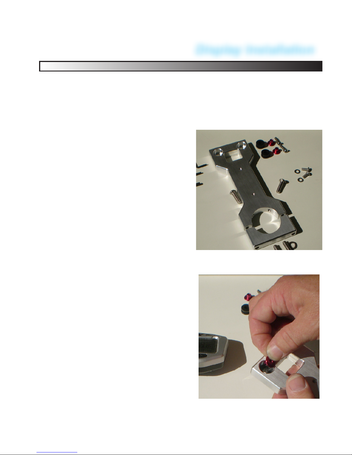
The parts shown include
rubber grommets inserted
into the display mounting
holes with 4mmx0.7x12mm
metric screws. Metric Allen
wrenches will be needed.
(See parts sheet)
The RED inserts are inserted
into the rubber grommets as
shown to the right. These are
stops to prevent the screws
from damaging the display.
The RED FLAT BACK is far-
thest away from the display. 13
Display Installation

Display Installation
14
Universal Bracket Mount:
Lay a soft cloth on the work surface
and lay the display face down. In-
stall the Display using the two 4mm x
12mm Allen head screws.
Notice the red at back is the bump
stop, the screws will stop when fully
compressed. The RED FLAT BACK
is farthest away from the display.
> DO NOT OVER TIGHTEN!
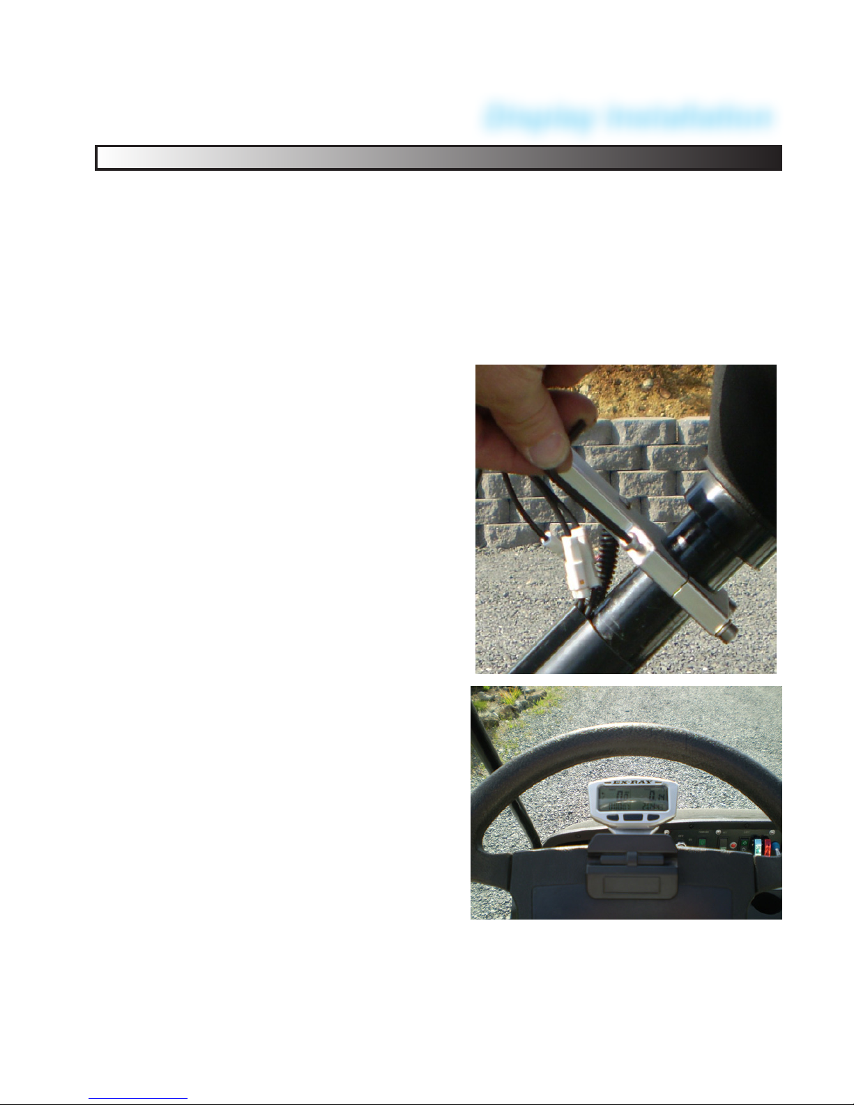
Install the pipe clamp onto the steer-
ing column.
Position the display 6 inches
(150mm) behind the steering wheel,
about 1 inch (25mm) away from the
steering wheel mounting hub.
Hand tighten the clamp bolt until the
display no longer moves and aligned
straight.
CNC Bracket Mount:
Steering tube column diameters vary between golf cart manufac-
turers, ensure you have the correct diameter before starting the
project. (Example: the 1.50” EZ-Go tube uses 1.51” Clamp)
MODELS:
• EXRAY-MEZ EZ-Go 1.51”
• EXRAY-MEZ-EZ RXV 1.59”
• EXRAY-MCC ClubCar 1.66”
• EXRAY-MYAM Yamaha 1.71”
• EXRAY-MCCP ClubCar with
Plastic Tube 1.76”
• EXRAY-MXRT-850E (ELEC)
EXRAY-MXRT-850G (Gas)
ClubCar XRT with Plastic
Tube 1.76”
The parts shown include rubber
grommets inserted into the display
mounting holes 4mm x 12mm met-
ric screws. Metric Allen wrenches
will be needed (not included). (See
parts sheet)
The RED inserts are inserted into
the DEEP DRILLED HOLE sec-
tion. These are stops to prevent the
screws from damaging the display.
The RED FLAT BACK is farthest
away from the display. 15
Display Installation

Display Installation
16
CNC Bracket Mount:
Lay a soft cloth on the work surface
and lay the display face down. In-
stall the Display using the two 4mm x
12mm Allen head screws.
Notice the red at back is the bump
stop, the screws will stop when fully
compressed.
> DO NOT OVER TIGHTEN!
Insert the two 6mmx40mm Allen
head bolts (Cap Screws) with 1-at
washer. (Note bolts may differ from
picture)
Position the display 6 inches
(150mm) behind the steering wheel,
about 1 inch (25mm) away from the
steering wheel mounting hub.
Hand tighten the 6mm bolts until
the display no longer moves and is
straight.
CLUB CAR with plastic tube see next
page. (MCCP and MXRT Models)
Club Car with plastic cover:
(MCCP and MXRT Models)
Tighten the bottom 6mmx40mm
bolts as shown on the previous
page.
Insert the two 6mmx20mm (or
6mmx25mm bolts, which ever
came with your kit) into the
45 degree staking holes. Hand
tight them to just touch the plastic
tube. Then making sure the display
is straight up, 1/4 turn each bolt
side. Do not overtighten.
The display should be inside the
steering wheel window. If the dis-
play is too high, move it farther
away down the steering column
and tighten.
Note: Some stainless steering cov-
ers differ in size. The tube may
need to be cut to allow the EX-RAY
to t directly onto the steel steering
column. Measure tube diameter.
Steering Column Mount:
Some Club Car models utilized plastic tube covers. The
diameter of the CNC bracket accounts for this tube and uses
45 degree “Stake bolts” which lock the display in place. This
process will “ding” the plastic tube permanently, but neces-
sary to lock the display in place.
Display Installation
17
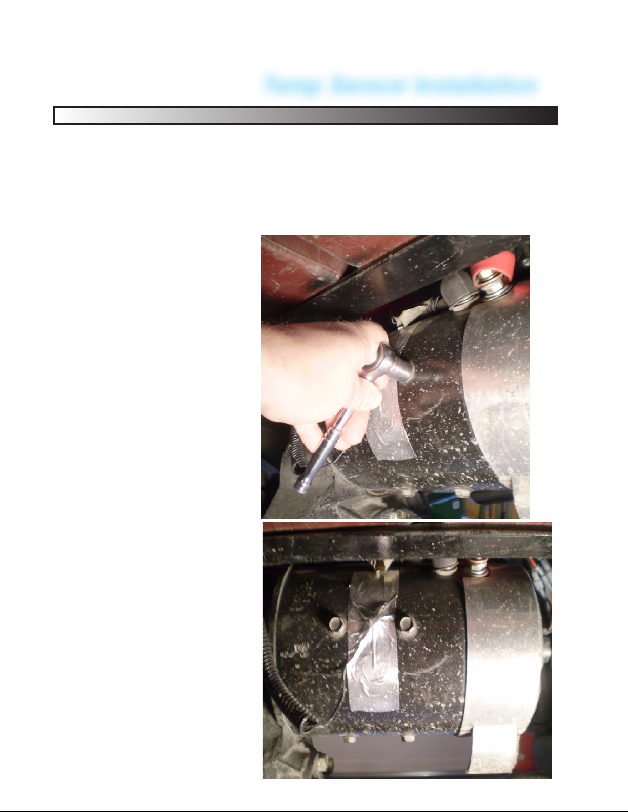
ELECTRIC MOTOR:
The temperature sensor
monitors the eld coil tem-
perature, an indication of
>75°C (167°F), the inter-
nal temperature is too hot.
Option 1: Performed by
authorized personnel,
Carefully remove the mo-
tor eld bolt and install the
temp sensor. Install the
bolt and torque to manu-
facturers specications.
Option 2: Use the sup-
plied tape, clean the area
with de-grease agent, dry,
and apply the tape over
the sensor and part of the
wire.
Temp Sensor Mount:
Electric Motor: Two options: 1) Motor eld coil bolt or secure
using the included Aluminized tape. (Both methods shown)
Gas Engine: 10mm bolt (optional water jacket sensor avail-
able, contact your dealer for more info).
Temp Sensor Installation
18

GAS ENGINE Temp Sensor Installation
GAS MOTOR:
Any bolt near the cylinder
head will provide good
indication. (Preferably a
mounting bolt that does
not require re-torquing the
head bolts).
CAUTION: THE CABLE
MUST NOT CONTACT
MUFFLER EXHAUST
COMPONENTS!
Secure the cable with
cable clamps. Watch for
CHAFFING points that
may damage the cable.
Follow the EXTENSION
CABLE guidelines to prop-
erly route the cable to the
display.
The Golf Cart gas engine Temp Sensor:
The typical installation is for Air Cooled engines. Cylinder
Head temperature is most critical. Oil temperature is also
a good indicator. Find a location that a bolt can safely be
removed and temp sensor can be installed.
19

Temp Sensor EXTENSION Installation
Temp Extension Cable:
Install and use the supplied cable ties to secure the 6 foot
temperature extension cable. Ensure the connectors are
securely attached, do not apply any stress on the wires as the
motor moves up and down.
20
FACING FORWARD FACING REARWARD
TAPE THE SPLIT LOOM
(NOT SUPPLIED)
INSERT THE
CONNECTORS
Table of contents
Popular Automobile Accessories manuals by other brands


Kargo Master
Kargo Master 40816 Instruction guide

Safe Fleet
Safe Fleet Prime Design AR1911 Assembly instructions

STO N SHO
STO N SHO SNS 339 Installation procedures

Phonocar
Phonocar 05143 instruction manual

Metra Electronics
Metra Electronics 99-8208 installation instructions

TOP VEHICLE TECH
TOP VEHICLE TECH KWPOR15 installation manual