EDT VisionLink XF User manual
User’s Guide
VisionLink XF
Camera Link fiber extender
for base mode through 80-bit operation
Date: 2019 March 19
Rev.: 0001

EDT, Inc. 2
EDT | Engineering Design Team, Inc.
3423 NE
John Olsen Ave
Hillsboro, OR 97124
U.S.A.
Tel: +1-503-690-1234 | Toll free (in U.S.A.): 800-435-4320
Fax: +1-503-690-1243
www.edt.com
TM
TM
EDT
and Engineering Design Team
are trademarks of Engineering Design Team, Inc. All other trademarks, service marks,
and copyrights are the property
of their respective owners†.
© 1997-2019 Engineering Design Team, Inc. All rights reserved.

EDT, Inc. 3
Terms of Use Agreement
Definitions. This agreement, between Engineering Design Team, Inc. (“Seller”) and the user or distributor (“Buyer”), covers the
use and distribution of the following items provided by Seller: a) the binary and all provided source code for any and all device
drivers, software libraries, utilities, and example applications (collectively, “Software”); b) the binary and all provided source code
foranyandall configurable or programmable devices (collectively, “Firmware”); and c)the computerboards andall otherphysical
components (collectively, “Hardware”). Software, Firmware, and Hardware are collectively referred to as “Products.” This
agreementalso covers Seller’spublished Limited Warranty (“Warranty”) and all other published manuals and product information
in physical, electronic, or any other form (“Documentation”).
License. Seller grants Buyer the right to use or distribute Seller’s Software and Firmware Products solely to enable Seller’s
Hardware Products. Seller’s Softwareand Firmware must beused on the same computer as Seller’s Hardware. Seller’s Products
and Documentation are furnished under, and may be used only in accordance with, the terms of this agreement. By using or
distributing Seller’s Products and Documentation, Buyer agrees to the terms of this agreement, as well as any additional
agreements (such as a nondisclosure agreement) between Buyer and Seller.
Export Restrictions. Buyer will not permit Seller’s Software, Firmware, or Hardware to be sent to, or used in, any other country
except in compliance with applicable U.S. laws and regulations. For clarification or advice on such laws and regulations, Buyer
should contact: U.S. Department of Commerce, Export Division, Washington, D.C., 20230, U.S.A.
Limitation of Rights. Seller grants Buyer a royalty-free right to modify, reproduce, and distribute executable files using the
Seller’s Software and Firmware, provided that: a) the source code and executable files will be used only with Seller’s Hardware;
b)Buyer agreesto indemnify,hold harmless,and defendSeller from and against any claims or lawsuits, including attorneys’ fees,
that arise or result from the use or distribution of Buyer’s products containing Seller’s Products. Seller’s Hardware may not be
copied or recreated in any form or by any means without Seller’s express written consent.
No Liability for Consequential Damages. In no event will Seller, its directors, officers, employees, or agents be liable to Buyer
for any consequential, incidental, or indirect damages (including damages for business interruptions, loss of business profits or
information, and the like) arising out of the use or inability to use the Products, even if Seller has been advised of the possibility
of such damages. Because some jurisdictions do not allow the exclusion or limitation of liability for consequential or incidental
damages, the above limitations may not apply to Buyer. Seller’s liability to Buyer for actual damages for any cause whatsoever,
and regardless of the form of the action (whether in contract, product liability, tort including negligence, or otherwise) will be
limited to fifty U.S. dollars ($50.00).
Limited Hardware Warranty. Seller warrants that the Hardware it manufactures and sells shall be free of defects in materials
and workmanship for a period of months from date of shipment to initial Buyer. This warranty does not apply to any product that
is misused, abused, repaired, or otherwise modified by Buyer or others. Seller’s sole obligation for breach of this warranty shall
be to repair or replace (F.O.B. Seller’s plant, Beaverton, Oregon, USA) any goods that are found to be non-conforming or
defective as specified by Buyer within 30 days of discovery of any defect. Buyer shall bear all installation and transportation
expenses, and all other incidental expenses and damages.
Limitation of Liability. In no event shall Seller be liable for any type of special consequential, incidental, or penal damages,
whether such damages arise from, or are a result of, breach of contract, warranty, tort (including negligence), strict liability, or
otherwise. All references to damages herein shall include, but not be limited to: loss of profit or revenue; loss of use of the goods
or associated equipment; costs of substitute goods, equipment, or facilities; downtime costs; or claims for damages. Seller shall
not be liable for any loss, claim, expense, or damage caused by, contributed to, or arising out of the acts or omissions of Buyer,
whether negligent or otherwise.
No Other Warranties. Seller makes no other warranties, express or implied, including without limitation the implied warranties
of merchantability and fitness for a particular purpose, regarding Seller’s Products or Documentation. Seller does not warrant,
guarantee, or make any representations regarding the use or the results of the use of the Products or Documentation or their
correctness, accuracy, reliability, currentness, or otherwise. All risk related to the results and performance of the Products and
Documentation is assumed by Buyer. The exclusion of implied warranties is not permitted by some jurisdictions. The above
exclusion may not apply to Buyer.
Disclaimer. Seller’s Products and Documentation, including this document, are subject to change without notice. Documentation
does not represent a commitment from Seller.

EDT, Inc. 4
Contents
Overview......................................................................................................................................................................... 5
Care and Cautions ................................................................................................................................................ 5
Related Resources................................................................................................................................................ 6
Cabling............................................................................................................................................................................ 7
Camera Link.......................................................................................................................................................... 7
Fiberoptic .............................................................................................................................................................. 7
Power and Auxiliary .............................................................................................................................................. 7
Setup .............................................................................................................................................................................. 8
DIP Switches and LEDs........................................................................................................................................ 9
Mounting and Safetying................................................................................................................................................ 10
Firmware....................................................................................................................................................................... 10
Transceivers ................................................................................................................................................................. 11
Pin Assignments........................................................................................................................................................... 12
Camera Link Connectors..................................................................................................................................... 12
Power Connector ................................................................................................................................................ 13
Cable Assembly – Lemo to Loose Wire..................................................................................................... 13
Cable Assembly – Lemo to Male DB9....................................................................................................... 13
Cable Assembly – Lemo to Female DB9 RS232.......................................................................................14
Power Supply................................................................................................................................................................ 15
Dimensions................................................................................................................................................................... 16

EDT, Inc. 5
VisionLink XF Camera Link Fiber Extender
Overview
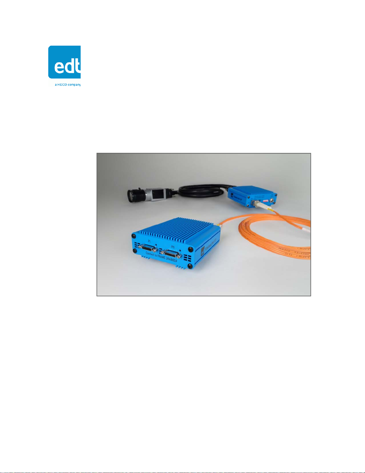
The VisionLink XF extends Camera Link (base through 80-bit mode) over fiber, providing electrical isolation and
extended range. It supports cameras from 20 to 85 MHz, and serial data rates up to 115.2 kb/s.
The VisionLink XF extender works with EDT or third-party framegrabbers (see Related Resources). The extender units
are designed to work in pairs: one unit connects to the camera and the other to the framegrabber with Camera Link
cabling; then the two units connect to each other with fiberoptic cabling. Figure 1 shows an example setup.
Figure 1. VisionLink XF extender pair – example setup (medium or 80-bit mode)
Care and Cautions
When opening and handling EDT products, always follow electrostatic dissipative procedures (see edt.com/static).
Each EDT product, though built to withstand a wide range of conditions as listed in its datasheet specifications, is still a
high-performance component which requires proper care for best results.
In particular, the connectors – especially the fiberoptic transceivers – must be kept clean and dry. If you suspect the
presence of moisture or debris in the connectors, use compressed air to do the following...
1) Blow the compressed air away from the equipment to clear any moisture or debris from the air nozzle.
2) Blow the compressed air directly into each connector to clear any moisture or debris there.
CAUTION To avoid damaging your eyesight, never look directly into any fiberoptic transceiver.

VisionLink XF Overview
6
2019 March 19
EDT, Inc.
Related Resources
The resources below may be helpful or necessary for your applications. For complete resources and documentation on
any EDT product, visit edt.com and navigate to the product page.
EDT resources
• VisionLink XF datasheet / specifications edt.com/product-data
• VisionLink XF quick start guide “
• Videos and tutorials “
• All EDT extenders edt.com/product-lines/camera-link-extenders/
• All EDT frame grabbers edt.com/product-lines/camera-link-frame-grabbers/
Third-party resources
• Camera Link specifications visiononline.org
• Providers of fiberoptic cabling assemblies:
– Borg Technologies borg-tech.com
– Cypress Industries cypressindustries.com
– Molex molex.com

VisionLink XF Cabling
7
2019 March 19
EDT, Inc.
Cabling
The VisionLink XF requires Camera Link, fiberoptic, and power cables, as explained below.
Camera Link
Use standard Camera Link cables (SDR-to-SDR or SDR-to-MDR) to connect the VisionLink XF units to the camera and
the framegrabber. EDT recommends that these cables should be one meter or less in length. You may use longer
cables, but they may introduce noise into your image data – particularly if you use a camera with a high pixel clock rate.
For Camera Link pin assignments, see Pin Assignments on page 12.
Fiberoptic
Use fiberoptic cabling to connect the two VisionLink XF units to each other. The type of cabling you need will depend
on where you install the system, and which transceivers you use (for transceiver specifications, see Transceivers on
page 11). EDT stocks a small number of options for fiberoptic cable assemblies; if these options do not meet your
needs, you should contact a provider of such assemblies (see Related Resources for some of these providers).
Power and Auxiliary
EDT ships your VisionLink XF extenders with a power adapter and a connecting cable. For options and pin
assignments, see Power Supply on page 15 and (under Pin Assignments) Power Connector on page 13.

VisionLink XF Setup
8
2019 March 19
EDT, Inc.
Setup
To set up your VisionLink XF extender pair...
1.
Power off all devices.
2.
In the host computer, install the
framegrabber according to its user’s
guide (for EDT framegrabbers, see
edt.com).
3.
P0 is connected to the base, or primary, port of the camera or framegrabber. P1 is connected to the medium/full,
or secondary, port of the camera or framegrabber. Connect the camera-end unit to the camera and the
framegrabber-end unit to the framegrabber with appropriate cables. See
Figure 2.
Figure 2. Connecting Camera Link cables to the VisionLink XF
4.
In each unit, insert a fiberoptic transceiver into the SFP+
port; then connect the two units with fiberoptic cabling and
close the bale straps on the transceivers.
5.
Verify that each DIP switch is set correctly (see
DIP Switches and LEDs on page 9).
6.
Connect each extender to its power supply (see
Power Supply on page 15).
7.
Power on, in this order: the framegrabber (in the host
computer); the framegrabber-end extender; the camera-end
extender; the camera.
8.
Verify that each LED is steady green (see
DIP Switches and LEDs on page 9).
a. SDR-to-SDR, part #016-15341 b. SDR-to-MDR, part #016-15340
VisionLink XF Setup
9
2019 March 19
EDT, Inc.
DIP Switches and LEDs
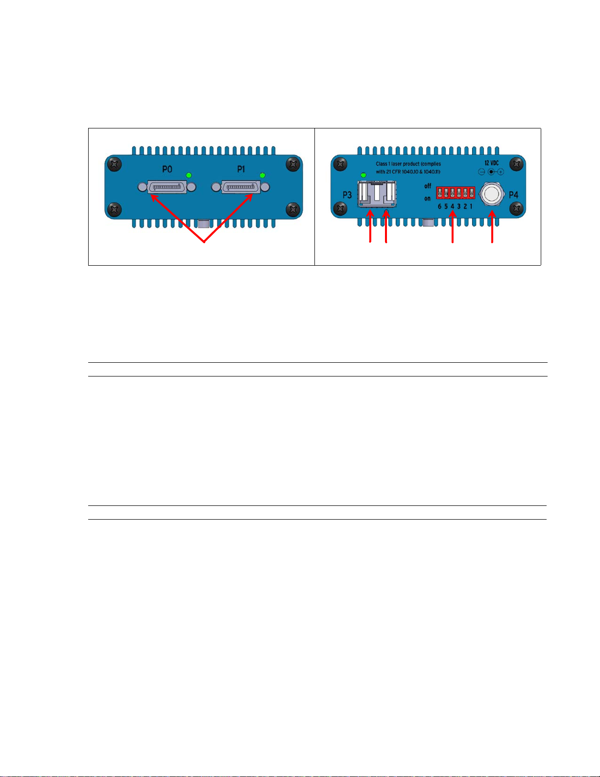
Figure 3 shows the extender’s ports and features, including the DIP switches and LEDs.
Figure 3. Ports and features
• The DIP switches indicate which device (camera or framegrabber, as labeled on the Camera Link end of the unit);
whether Power over Camera Link (PoCL) is on or off; and whether the unit is set for program mode or normal mode.
• The LEDs indicate the status of each port.
Table 1 and Table 2 explain the details.
a. Camera Link end b. Fiberoptic end
Table 1. DIP switch settings
#Function On Off Details
1Which device to connect camera framegrabber System reads this switch at boot time only.
2Port 1 (P1): PoCL P1: PoCL on P1: PoCL off Validfor camera-endunitsonly. Thisswitch alwaysshould be“off”
for the framegrabber-end unit (that is, whenever switch 1 is “off”).
3Port 0 (P0): PoCL P0: PoCL on P0: PoCL off Validfor camera-endunits only.Thisswitch alwaysshould be“off”
for the framegrabber-end unit (that is, whenever switch 1 is “off”).
4Program vs. normal mode program normal System reads this switch at boot time only.
5undefined -- -- --
6undefined -- -- --
Table 2. LED behaviors
Unit LED location Behavior Meaning
Camera SDR Green, no flash Good; the camera (pixel clock) is detected
Green, quick flash (10Hz) Error; the camera (pixel clock) is not detected
Red, no flash Good; PoCL is enabled
Red, quick flash (10Hz) Error; PoCL is enabled, but a non-PoCL device is connected to
the unit (SafePower circuit is open)
SFP+ Green, no flash Good; the other unit is detected at the framegrabber end
Red, slow flash (1Hz) Error; the other unit is not detected at the framegrabber end
Red, quick flash (10Hz) Error; the other unit is detected, but it is a camera-end unit (it
should be a framegrabber-end unit)
Framegrabber SDR Green, no flash Good; data is transferring between the unit and the framegrabber
SFP+ Green, no flash Good; the other unit is detected at the camera end
Red, slow flash (1Hz) Error; the other unit is not detected at the camera end
Red, quick flash (10Hz) Error; the other unit is detected, but it is a framegrabber-end unit
(it should be a camera-end unit)
SDR ports (“P0” and “P1”) with LEDs
transmit / receive
DIP switches
Power (“P4”)
SFP+ port
(“P3”) with
LED:
VisionLink XF Mounting and Safetying
10
2019 March 19
EDT, Inc.
Mounting and Safetying
In some applications – for example, aircraft or other high-vibration environments – you may need to mount the extender,
safety the transceiver, or do both.
• To mount the extender, you can attach a custom (user-provided) bracket via the two 4-40 mounting posts on the
bottom of the case; for the precise locations of these holes, see Dimensions on page 16.
• To safety the fiberoptic transceiver, you can use aviation safety wire.
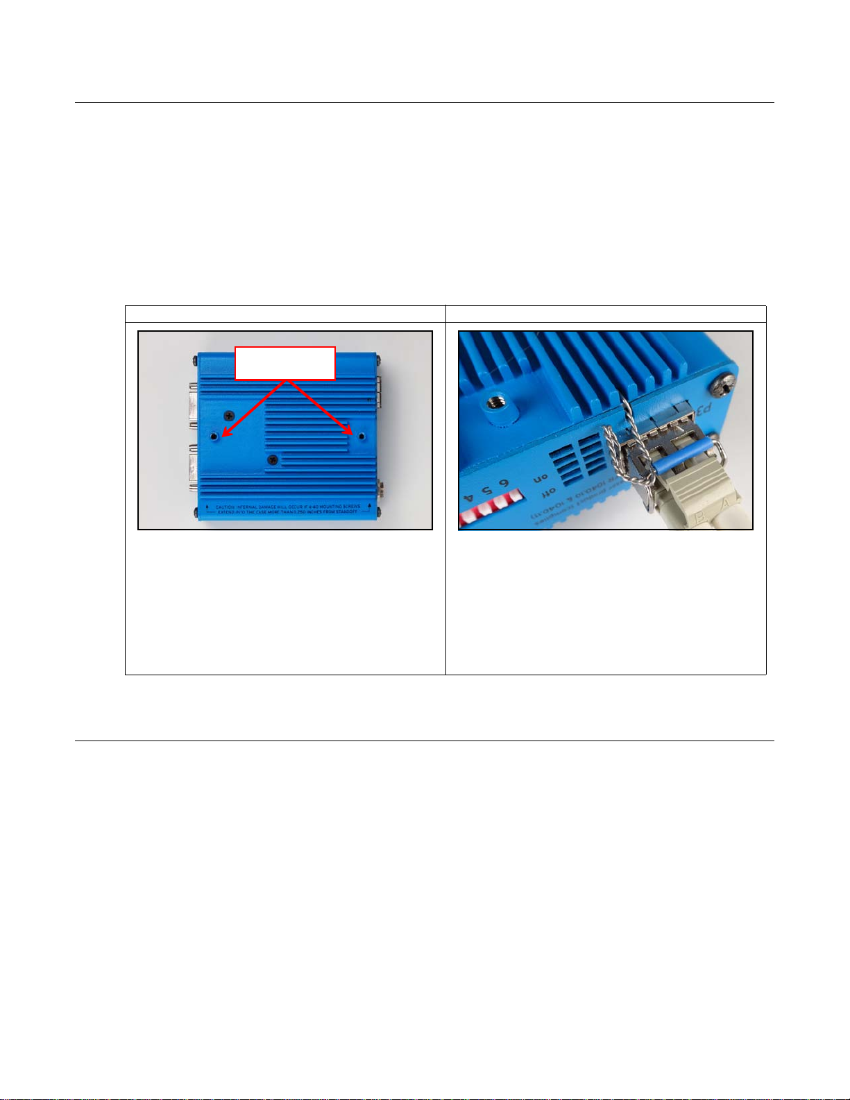
For details on how to use the mounting holes and safety wire, see Figure 4.
Figure 4. Mounting and safetying
Firmware
Eachextender ispreconfigured withEDT firmwarewhich controls its operation.EDT providesperiodicfirmwareupdates
which currently must be performed onsite at EDT. If you are notified that an update is available or needed, contact EDT.
a. Mounting holes b. Transceiver with safety wire
To use the 4-40 thread mounting holes:
Add your own custom bracket, designed to match the exact
location of the holes (see Dimensions on page 16).
CAUTION – Internal damage will occur if 4-40 mounting
screws extend into the case more than 0.250 inches from
standoff.
To safety the transceiver:
Threadthe safety wire through thebalestrap and thehole and
notch in the backshell. EDT recommends .020 dia. aviation
safety wire from an aviation supplier – for example, Aircraft
Spruce and Specialty (www.aircraftspruce.com). For aviation
applications, follow relevant Federal Aviation Administration
(FAA) guidelines and best practices; see the FAA Advisory
Circular (AC) 43.13-1B at www.faa.gov.
Mounting holes
Safety wire
running through
hole,
notch,no
and bale strap

VisionLink XF Transceivers
11
2019 March 19
EDT, Inc.
Transceivers
The VisionLink XF extender supports various types of small form-factor pluggable (SFP+) transceivers with matching
multimode fiber (MMF) or single mode fiber (SMF), as shown in Table 3.
Alternatively, the following transceivers are available as options...
• Bidirectional transceivers – These support data transmit and receive over a single fiber using two separate wave-
lengths (for example, 1310 nm and 1550 nm). They can be used in a matched pair, 1310/1550 and 1550/1310.
Typical usage is with an optical rotary joint.
• CWDM transceivers – These support data transmission on a specific wavelength (1270 nm to 1610 nm). They can
be used with a CWDM multiplexer and demultiplexer which can support up to 16 wavelengths over a duplex fiber
between the multiplexer and demultiplexer. Typical usage is with an optical network of devices to be served by one
duplex fiber.
Typically, it is easiest to connect all transceivers using LC duplex fiber; but if you want to use fewer fibers, in some
atypical cases it is possible to do so – for example, when using single-fiber (bidirectional) transceivers, as above.
Table 3. Transceiver + fiber combinations
Wavelength Cable Range at 10 Gb/s *
33 meters62.5-micron MMF (OM1)850 nm
300 meters50-micron MMF (OM3)850 nm
Up to 10 kilometers9-micron SMF1310 nm

VisionLink XF Pin Assignments
12
2019 March 19
EDT, Inc.
Pin Assignments
This section provides pin assignments for each connector.
Camera Link Connectors
Below are the pin assignments for the Camera Link SDR26 connectors.
Camera
or simulator
end
Frame
grabber
end
Camera Link signal
(base mode,
primary connector)
Camera Link signal
(medium mode,
secondary connector)
Camera Link signal
(full mode,
secondary connector)
inner shield / ground*inner shield / ground*inner shield / ground*1*1* inner shield / ground*inner shield / ground*inner shield / ground*14*14* Y0–Y0–X0–252 Y0+Y0+X0+1215 Y1–Y1–X1–243 Y1+Y1+X1+1116 Y2–Y2–X2–234 Y2+Y2+X2+1017 Yclk–Yclk–Xclk–225 Yclk+Yclk+Xclk+918 Y3–Y3–X3–216 Y3+Y3+X3+819 100 ohmsunusedSerTC+207 terminatedunusedSerTC–720 Z0–unusedSerTFG–198 Z0+unusedSerTFG+621 Z1–unusedCC1–189 Z1+unusedCC1+522 Z2–unusedCC2+1710 Z2+unusedCC2–423 Zclk–unusedCC3–1611 Zclk+unusedCC3+324 Z3–unusedCC4+1512 Z3+unusedCC4–225 inner shield / ground*inner shield / ground*inner shield / ground*13*13* inner shield / ground*inner shield / ground*inner shield / ground*26*26*
* With PoCL enabled, pins 1 and 26 change to +12 V DC power, while pins 13 and 14 change to +12 V DC power return.

VisionLink XF Pin Assignments
13
2019 March 19
EDT, Inc.
Power Connector
Below are the pin assignments for the power connector – either a standard coaxial Switchcraft or an optional Lemo.
Figure 5. Pin assignments – standard Switchcraft or optional Lemo connector
With the Lemo, you can use various cables that allow auxiliary signals.
Cable Assembly – Lemo to Loose Wire
The Lemo to loose wire cable assembly (EDT part #016-12650) can be wired as needed or connected to various types
of connectors, depending on your application.
Cable Assembly – Lemo to Male DB9
The Lemo to male DB9 cable assembly (EDT part #016-12718) supports signals that can be used as an auxiliary
signaling system for a variety of purposes.
For example, with custom firmware you could control the camera’s pan and servo motors, or set up a hardware trigger
that is local to either end. If you wish to explore these options, contact EDT.
Unlike the DB9 in the female assembly, this DB9 has no looped-back signals or integrated level conversion.
Outer ring is
ground.
Pin 1 is power
to the extender
(+12 V DC).
Key in connector barrel (at top).
Pin 2 is power to the extender (+12 V DC).
Pin 7 is ground (for signals and power).
Pins 1, 3, 4, 5, 6 (defined by firmware used in extender)
typically are used at CMOS +3.3 V signal levels, though
pins 1,6 and 3,4 can be configured as LVDS pairs.
Table 4. Pin assignments – Lemo to loose wire
Lemo pin Wire color Standard firmware Signal level Comments
CMOS +3.3 VAUX_TX, primary auxiliary transmit UARTgreen1 (output)
All five CMOS 3.3 V signals go to
FPGA I/O 3.3V pins using series
100-ohm resistors.
Custom firmware can be used to
configure these pins as input or
output.
+12 Vpower to extenderred2
AUX2_TX, secondarorange3 (output) CMOS +3.3 Vy auxiliary transmit
CMOS +3.3 VAUX2_RX, secondary auxiliary receivebrown4 (input)
SYNC, can be configured as an outgoing copy ofwhite5 the camera’s frame-valid signal CMOS +3.3 V
CMOS +3.3 VAUX_RX, primary auxiliary receive UARTblue6 (input)
groundgroundblack7
1
(Switchcraft)
5
6
7
1
4
2
3
(Lemo)

VisionLink XF Pin Assignments
14
2019 March 19
EDT, Inc.
Table 5 shows the pin assignments and how the standard firmware uses each wire.
Cable Assembly – Lemo to Female DB9 RS232
The Lemo to female DB9 cable assembly (EDT part #016-12445) supports integrated CMOS +3.3 V to RS232 level
converters on a small circuit board inside the DB9 connector shell.
This cable is designed to plug in directly to a host computer serial port. The cable offers an auxiliary serial UART
connection over the fiber, in addition to the UART normally associated with the Camera Link standard. This auxiliary
UART can be used, for example, to control the camera’s pan and zoom servo motors from the host at 115.2 kb/s or less.
Alternatively, it can be used for other low bandwidth signals.
Unlike the DB9 in the male assembly, this DB9 does not supply power to the extender. Instead, a red wire (power) and
a black wire (ground), each 24 inches long, are left loose so you can hook up your own power source. The required
power is 12 V DC.
Table 6 shows the pinout and how the standard firmware uses each wire. DB9 pins 1, 4, and 6 are wired together and
unconnected, 7 and 8 also are wired together, and 9 also is unconnected; these signals are not otherwise used.
Table 5. Pin assignments – male DB9 cable
Lemo pin Color DB9 pin Standard firmware Signal level Comments
–[unused]1––
All five CMOS 3.3 V
signals go to FPGA I/O
3.3V pins using series
100-ohm resistors.
Customfirmwarecan be
used to configure these
pins as input or output.
–[unused]6––
CMOS +3.3 VAUX_TX, primary auxiliary transmit UART2green1 (output)
+12 Vpower to extender9red2
CMOS +3.3 VAUX2_TX, secondary auxiliary transmit7orange3 (output)
CMOS +3.3 VAUX2_RX, secondary auxiliary receive8brown4 (input)
SYNC, can be configured as an outgoing copy of4white5 the camera’s frame-valid signal CMOS +3.3 V
CMOS +3.3 VAUX_RX, primary auxiliary receive UART3blue6 (input)
groundground5black7
Table 6. Pin assignments – female DB9 cable
Lemo pin Wire color DB9 pin Standard firmware Signal level
–[unused]1––
–[unused]6––
AUX_TX, primary auxiliary transmi2green1 (output) RS232 (at DB9) to CMOS +3.3 V (at Lemo)t UART
+12 Vpower to extender–red2
–reserved7orange3
–reserved8brown4
–reserved4white5
RS232 (at DB9) to CMOS +3.3 V (at Lemo)AUX_RX, primary auxiliary receive UART3blue6 (input)
groundground–black7

VisionLink XF Power Supply
15
2019 March 19
EDT, Inc.
Power Supply
Each extender has an internal switching regulator which supports 12 V DC. For pin information and polarity on the
standard Switchcraft or optional Lemo power connector, see Power Connector on page 13.
Table 7 shows the base-mode power supply requirements.
Table 7. Power supply requirements – base mode
U.S. International
Voltage in 100–240 V, 50–60 Hz
from AC mains 100–240 V, 50–60 Hz
from AC mains
Voltage out 12 V DC; power supply
includes a U.S.-standard
power plug
12 V DC; power supply
includes four international
power plug adapters
Connector,
standard Switchcraft 760K Switchcraft 760K
Connector,
Lemo option FGG.0B.307.CLAD.56 FGG.0B.307.CLAD.56
VisionLink XF Dimensions
16
2019 March 19
EDT, Inc.
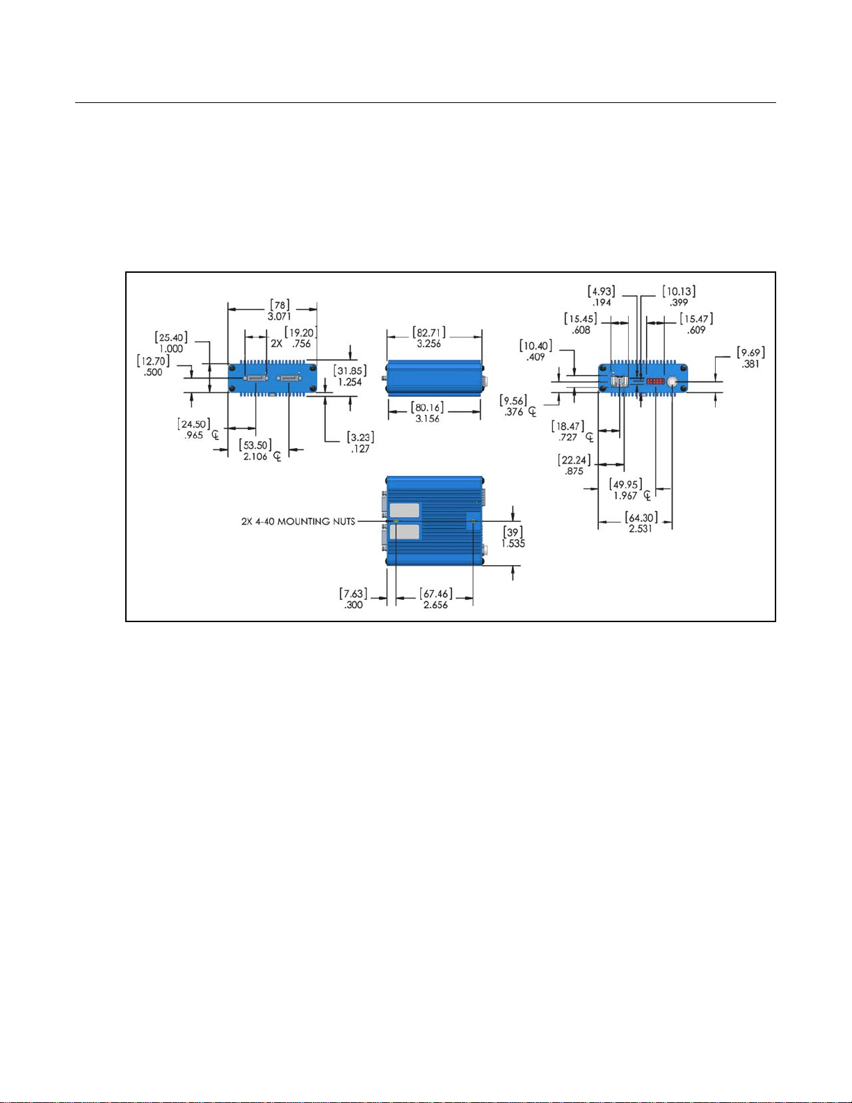
Dimensions
This section shows the dimensions of the VisionLink XF.
The Switchcraft power connector has an outside diameter of 0.31 inch; the optional Lemo power connector has an
outside diameter of 0.35 inch.
NOTE Connector dimensions are approximate; for precise dimensions, see the manufacturer’s specifications.
Figure 6. Extender dimensions

VisionLink XF Dimensions
17
2019 March 19
EDT, Inc.
Revision Log
Below is a history of modifications to this guide.
Date Rev By Pg(s) Detail
20170215 0000 PH et al. All • Created new guide.
20190319
0001
BB et al.
8
• Added details to cable connections in Setup section.
Table of contents
Other EDT Extender manuals


