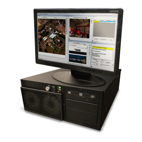
Edwards FireWorks UL5W7 User manual

FireWorks UL5W7
Workstation Installation
Manual
P/N 3101492-EN • REV 06 • ISS 05AUG13

Copyright © 2013 UTC Fire & Security Americas Corporation, Inc.
All rights reserved
This document may not be copied in whole or in part or otherwise
reproduced without prior written consent from UTC Fire & Security
Americas Corporation, Inc., except where specifically permitted
under US and international copyright law.
Trademarks and
patents
The FireWorks name and logo are trademarks of
UTC Fire & Security.
Other trade names used in this document may be trademarks or
registered trademarks of the manufacturers or vendors of the
respective products.
Manufacture
r
Edwards, A Division of UTC Fire & Security
Americas Corporation, Inc.
8985 Town Center Parkway, Bradenton, FL 34202, USA.
FCC compliance This device complies with part 15 of the FCC Rules. Operation is
subject to the following two conditions: (1) This device may not
cause harmful interference, and (2) this device must accept any
interference received, including interference that may cause
undesired operation.
Contact information
For contact information, see www.edwardsutcfs.com.

FireWorks UL5W7 Workstation Installation Manual i
Content
Important information iii
Chapter 1 Introduction 1
About this manual 2
About FireWorks 2
About the FireWorks UL5W7 workstation 3
Compatible devices and hardware options 7
UL 864 programming requirements 9
Chapter 2 Installation 11
Quick setup 12
Setting up a FireWorks UL5W7 workstation 13
Installing option cards 14
Logging on to the FireWorks UL5W7 workstation 15
Changing Windows logon passwords 16
Setting up monitors 16
Connecting printers 19
Connecting AC power 20
Installing the FireWorks UL5W7 workstation on a desk or
bench 22
Installing the FireWorks UL5W7 workstation in a rack 24
Control panel RS-232 wiring connections 26
Connecting digital alarm communicator receivers 29
Connecting iO Series control panels 33
Activating the FireWorks software 38
Chapter 3 Applications 39
Extending the distance between a FireWorks UL5W7
workstation and a control panel 40
EST3 to FireWorks redundant communication wiring 42
Multiple FireWorks 44
Passing commands between control panels 45
Security and access applications 48
Fire applications 48
Chapter 4 Troubleshooting 49
Fire alarm control panel to workstation communication
problems 50
Workstation hard drive failure 52

ii FireWorks UL5W7 Workstation Installation Manual
Appendix A Calculations 55
UPS sizing calculations 56
Attenuation worksheet 59
Appendix B Listing requirements 61
Listing requirements 62
Index 65

FireWorks UL5W7 Workstation Installation Manual iii
Important information
Regulatory information
This product has been designed to meet the requirements of NFPA 72 National
Fire Alarm and Signaling Code, UL 864 Standard for Control Units and
Accessories for Fire Alarm Systems, and CAN/ULC-527 Standard for Control
Units for Fire Alarm Systems.
Industry Canada information
Note: The Industry Canada label identifies certified equipment. This certification
means that the equipment meets certain telecommunications network protective,
operational, and safety requirements. Industry Canada does not guarantee the
equipment will operate to the user’s satisfaction.
Before installing this equipment, users should ensure that it is permissible to be
connected to the facilities of the local telecommunications company. The
equipment must also be installed using an acceptable method of connection. The
customer should be aware that compliance with the above conditions may not
prevent degradation of service in some situations.
Repairs to certified equipment should be made by an authorized Canadian
maintenance facility designated by the supplier. Any repairs or alterations made
by the user to this equipment, or equipment malfunctions, may give the
telecommunications company cause to request the user disconnect the
equipment.
Users should ensure for their own protection that the electrical ground
connections of the power utility, telephone lines, and internal metallic water pipe
system, if present, are connected together. This precaution may be particularly
important in rural areas.
Caution: Users should not attempt to make such connections themselves, but
should contact the appropriate electric inspection authority, or electrician, as
appropriate.
Limitation of liability
To the maximum extent permitted by applicable law, in no event will UTCFS be
liable for any lost profits or business opportunities, loss of use, business
interruption, loss of data, or any other indirect, special, incidental, or
consequential damages under any theory of liability, whether based in contract,
tort, negligence, product liability, or otherwise. Because some jurisdictions do not

iv FireWorks UL5W7 Workstation Installation Manual
allow the exclusion or limitation of liability for consequential or incidental
damages the preceding limitation may not apply to you. In any event the total
liability of UTCFS shall not exceed the purchase price of the product. The
foregoing limitation will apply to the maximum extent permitted by applicable law,
regardless of whether UTCFS has been advised of the possibility of such
damages and regardless of whether any remedy fails of its essential purpose.
Installation in accordance with this manual, applicable codes, and the instructions
of the authority having jurisdiction is mandatory.
While every precaution has been taken during the preparation of this manual to
ensure the accuracy of its contents, UTCFS assumes no responsibility for errors
or omissions.
Advisory messages
Advisory messages alert you to conditions or practices that can cause unwanted
results. The advisory messages used in this document are shown and described
below.
WARNING: Warning messages advise you of hazards that could result in injury
or loss of life. They tell you which actions to take or to avoid in order to prevent
the injury or loss of life.
Caution: Caution messages advise you of possible equipment damage. They tell
you which actions to take or to avoid in order to prevent the damage.
Note: Note messages advise you of the possible loss of time or effort. They
describe how to avoid the loss. Notes are also used to point out important
information that you should read.

FireWorks UL5W7 Workstation Installation Manual 1
Chapter 1
Introduction
Summary
This chapter provides a brief introduction to the FireWorks UL5W7 workstation,
and summarizes listing requirements.
Content
About this manual 2
About FireWorks 2
About the FireWorks UL5W7 workstation 3
Front panel features 3
Rear panel features 4
Motherboard cable connections 5
PCWD3 cable connections 6
Memory configuration 7
Opening and closing the DVD drive 7
Compatible devices and hardware options 7
UL 864 programming requirements 9

Chapter 1: Introduction
2 FireWorks UL5W7 Workstation Installation Manual
About this manual
This manual is for the FireWorks UL5W7 workstation models described below.
Model Description
FWUL5W7 Workstation, Intel Core 2 Duo CPU, 500 GB hard drive, DVD drive,
4 GB RAM (8 GB max.), Windows 7 Ultimate OS
FWUL5RAIDW7 [1] Workstation, Intel Core 2 Duo CPU, 500 GB RAID 1 hard drive array,
DVD drive, 4 GB RAM (8 GB max.), Windows 7 Ultimate OS
[1] RAID 1 provides fault tolerance through disk mirroring. Two separate hard drives are used.
Both hard drives store the same data. If one drive fails, the other drive continues to operate with
all of the data intact. The total capacity of the array of drives is limited to the capacity of a single
drive. RAID 1 offers reliable data protection by providing 100% redundancy. If a drive fails, it is
easily replaced. All the data is automatically copied to the replacement drive.
This manual is for authorized and product-certified distributors who are
responsible for the installation of fire alarm equipment. It is assumed that you are
already familiar with multiplex fire alarm systems and the relevant codes and
standards.
The manual shows you how to install the hardware associated with a FireWorks
display and control system. It does not show you how to install or program the
FireWorks software.
About FireWorks
The FireWorks UL5W7 workstation and FireWorks graphical command interface
software comprises a computerized display and control system. You can use the
FireWorks UL5W7 workstation with the following:
• EST3, EST3X, and combination EST3-EST3X systems
• iO Series systems
• EST2 stand-alone systems
• IRC-3 systems
• FCC systems
FireWorks lets you use one or more display computers to monitor and control
several networks of multiplex signaling systems, and card access systems.

Chapter 1: Introduction
FireWorks UL5W7 Workstation Installation Manual 3
About the FireWorks UL5W7 workstation
Front panel features
Figure 1: Front panel features
(1) ON/OFF key switch
(2) USB connectors
(3) Trouble LED
(4) Power LED
(5) Hard drive LED
(6) DVD drive
(7) DVD drive OPEN/CLOSE button
(8) DVD drive LED
(9) Optional drive bays (not used)
(10) Air filter
(11) Front fan (Fan 2)
(12) Front fan (Fan 3)
(6)
(7)
(9)
(8)
(1) (2) (3) (4) (5)
(
11
)
(
12
)
(
10
)

Chapter 1: Introduction
4 FireWorks UL5W7 Workstation Installation Manual
Rear panel features
Figure 2: Rear panel features
(1) Power connector
(2) Mouse connector
(3) Keyboard connector
(4) USB 2.0 connectors (6X)
(5) Digital (DVI) output
See “Setting up monitors” on page 16 for
more information.
(6) Audio connectors, not used
(7) Not used
(8) Expansion slots (PCI1 to PCI3)
See “Installing option cards” on page 14
for more information.
(9) PCWD3 watchdog card (factory installed)
Note: You must add the watchdog card to
your FireWorks project.
(10) Ethernet connectors (2X), not used
(11) Rear fan (Fan 4)
(12) Analog (VGA) output
(
7
)
(
1
)
(
8
)
(
3
)
(
2
)
(
12
)
(
11
)
(9)
(
4
)
(
5
)
(
6
)
(
10
)
(
4
)

Chapter 1: Introduction
FireWorks UL5W7 Workstation Installation Manual 5
Motherboard cable connections
Figure 3: Motherboard cabling diagram
(1) 12 V power connector
(2) Memory slot 1
(3) Memory slot 2
(4) Memory slot 3
(5) Memory slot 4
(6) ATX power connector
(7) Disk drive 1 (SATA 0)
(8) Disk drive 2 (SATA 1)
(9) DVD drive (SATA 5)
(10) Disk drive LED
(11) Power LED
(12) ON/OFF key switch
(13) Front panel
(14) PCWD3 daughter card
(15) PCWD3 PCI card
(16) Expansion card slots
(1)
(
6
)
(
7
)
(
8
)
(
9
)
(10) (11)
(12)
(13)
(14)
(15)
(
16
)
(2)
(3)
(4)
(5)

Chapter 1: Introduction
6 FireWorks UL5W7 Workstation Installation Manual
PCWD3 cable connections
Figure 4: PCWD3 cabling diagram
(1) Power Supply fan (Fan 8)
(2) Rear fan (Fan 4)
(3) Front trouble LED
(4) Front fan (Fan 3)
(5) Front fan (Fan 2)
(6) CPU fan (Fan 1)
(7) Power connection from workstation power
supply
USB
RS232
USB
JP2
A
L
A
RM
RESET
FAN1 FAN2 FAN3 FA N4 FAN5 FAN 6 FAN7 FAN8
A
RM
1
COM1
JP1
TX
GND
RX
1
1
5
12C
(1)
(2)
(4)
(5)
(3)
J16
(6)
!
J6
J8
J7
JP1
J3
J5
J4
J1
J2
J14
JP2JP3
J11
S1
J13
+5V +12V
FAN STARTUP
JP4
JP5
JP6
JP8
JP7
ADDRESS
0 1
PANEL BU Z Z E R
J12
PANEL LED
J9 J10
REMOTE SENSOR 1
REMOTE SENSOR 2
N.C.
N.C.
N.C.
N.C.N.C.N.C.
RD
WH
RD
WH
(7)
(7)
RD

Chapter 1: Introduction
FireWorks UL5W7 Workstation Installation Manual 7
Memory configuration
FireWorks UL5W7 workstations support dual channel memory configurations.
Single channel memory configurations and mismatched memory are not
supported. Install memory only as shown below. See Figure 3 on page 5 for
memory slot locations.
Table 1: Supported memory configurations
Channel A Channel B
Total RAM Slot 1 Slot 2 Slot 3 Slot 4
4 GB [1] 2 GB N/A 2 GB N/A
8 GB 2 GB 2 GB 2 GB 2 GB
[1] Standard memory configuration.
Opening and closing the DVD drive
The disc tray on the DVD drive does not close when you push it. Pushing the
disc tray to close it can damage the drive mechanism. Always use the DVD disc
drive OPEN/CLOSE button (see Figure 1 on page 3) to open and close the disc
tray.
Compatible devices and hardware options
The following tables list the devices and hardware options that have been tested
and proven compatible with the FireWorks UL5 workstation.
Table 2: Compatible monitors
Model Description Installation sheet
FW-19LCDWTS Monitor, LCD,19 inch, wide, capacitive touch screen 3101916
FW-22LCDWTS Monitor, LCD, 22 inch, wide, capacitive touch screen 3101917
FW-42LCDWTS Monitor, LCD, 42 inch, wide, surface acoustic wave
(SAW) touch screen
3101918
Table 3: Compatible subassemblies
Mod el Description Installation sheet
PCCA5 Power cord conduit adapter 3101828
FW-NCCA5 Network cable conduit adapter 3101762

Chapter 1: Introduction
8 FireWorks UL5W7 Workstation Installation Manual
Mod el Description Installation sheet
DTK-120HW DITEK surge protector N/A
PCWD3 Watchdog card N/A
FW-SP4i RS-232 serial four port expander card 3100897
FW-NIC PCI network card 3101498
Table 4: Compatible accessories
Model name Description Installation sheet
FW-HD5W7 Replacement hard drive for FWUL5W7
workstation (Windows 7 Ultimate OS)
3101494-EN
FW-HD5RAIDW7 Replacement hard drive for FWUL5RAIDW7
workstation (Windows 7 Ultimate OS)
3101532-EN
FWUL5RAM2G 2 GB memory module 3102020-EN
Mini-Mux/ FCOM-FIB Combination RS-232/Fiber optic communication
interface card
387059
PT-1S System event printer 3100989
MN-COM1S Ethernet to RS-232 interface module 3101601
MN-FVPN VoIP encoder/decoder module 3101583
MN-NETRLY4 Network relay module 3101827
MN-NETSW1 Ethernet switch, fiber optic, multimode 3101602
MN-NETSW2 Ethernet switch, fiber optic, single mode 3101931
MFC-A Accessory enclosure 387453
Bosch D6600 Digital alarm communicator receiver N/A
Osborne Hoffman
OH2000E
Digital alarm communicator receiver N/A
FW-19LCDWRACK Rack mount kit for model FW-19LCDWTS
monitor
N/A
FW-42LCDHMK1 Wall mount bracket kit, single 42-inch LCD
monitor, horizontal
N/A
FW-42LCDVMK1 Wall mount bracket kit, single 42-inch LCD
monitor, vertical
N/A
FW-42LCDVMK2 Wall mount bracket kit, dual 42-inch LCD
monitor, vertical
N/A
RKU-61-24B Cabinet, 19 inch, rack-mount N/A

Chapter 1: Introduction
FireWorks UL5W7 Workstation Installation Manual 9
UL 864 programming requirements
NOTICE TO USERS, INSTALLERS, AUTHORITIES HAVING JURISIDICTION, AND OTHER INVOLVED
PARTIES
This product incorporates field-programmable software. In order for the product to comply with
the requirements in the Standard for Control Units and Accessories for Fire Alarm Systems,
UL 864, certain programming features or options must be limited to specific values or not used as
indicated below.
Program feature or option Permitted in
UL 864? (Y/N)
Possible Settings or
operation
Settings Permitted in
UL 864
SYSCONTROL_RESOUND
_
24_HOUR
Y 0 (disabled), 1 (enabled) 1 (enabled)
SYSCONTROL_SELECT
_
HIGHEST_PRIORITY
Y 0 (disabled), 1 (enabled) 1 (enabled)
SYSCONTROL_SUPERVISORY
_
GOLD
Y 0 (yellow), 1 (gold) 0 (yellow)
UL_NINTH_EDITION_ACPOWER
_
TIMEOUT_HOURS
Y 0 to 9 (hours) 1, 2, 3 (hours)
Event Filter
Event Filter Types (Alarm,
Supervisory, Trouble,
Monitor, Security, Test,
Disable)
EST3 partitions
Access (Display, Printer,
History)
Use Filtering Schedule
Y
Enable, Disable
Enable, Disable
Enable, Disable
Enable, Disable
Enable
Enable, Disable
Enable
Enable
A
dding a watchdog card Y Added, Not added Added
SYSCONTROL_BELL_SILENCE
_
MINUTES
Y 0 to <32k 0 to 240
Clear All Account Events N Disabled, Enabled Disabled
Event Selection Method Y Maintain Selected Event
Select High Priority
Select Newest
Select Newest (if Higher
or Equal Priority)
Select High Priority
Local Mode of Operation N Disable, Enable Disable

Chapter 1: Introduction
10 FireWorks UL5W7 Workstation Installation Manual

FireWorks UL5W7 Workstation Installation Manual 11
Chapter 2
Installation
Summary
This chapter provides instructions for installing your FireWorks UL5W7
workstation.
Content
Quick setup 12
Setting up a FireWorks UL5W7 workstation 13
Installing option cards 14
Logging on to the FireWorks UL5W7 workstation 15
Changing Windows logon passwords 16
Setting up monitors 16
Connecting printers 19
Connecting AC power 20
Installing the FireWorks UL5W7 workstation on a desk or bench 22
Installing the FireWorks UL5W7 workstation in a rack 24
Control panel RS-232 wiring connections 26
Connecting digital alarm communicator receivers 29
Digital alarm communicator receiver setup overview 29
Digital alarm communicator receiver wiring connections 31
Connecting iO Series control panels 33
IP digital alarm communicator receiver setup overview 34
Connecting the RS-232 null modem cable 35
Activating the FireWorks software 38

Chapter 2: Installation
12 FireWorks UL5W7 Workstation Installation Manual
Quick setup
Figure 5: Quick setup diagram
(1) Primary monitor (VGA)
(2) Optional secondary monitor (DVI)
Requires a DVI-D (single link) video cable,
purchased locally.
(3) Back panel connectors
(4) Mouse
(5) Keyboard
(6) PT-1S system event printer
(
2
)
(
1
)
(6)
(4)
(5)
(3)
TOUCH PANEL TOUCH PANEL

Chapter 2: Installation
FireWorks UL5W7 Workstation Installation Manual 13
Setting up a FireWorks UL5W7 workstation
The following procedure describes setting up a FireWorks UL5W7 workstation
and connecting it to a control panel. The steps may refer you to other sections of
this manual or to other documentation.
Caution: Equipment damage hazard. Turn off the workstation and disconnect
AC power before installing or removing option cards, and connecting or
disconnecting external equipment.
Note: When configured as a proprietary supervision station, you can use the
FireWorks UL5W7 workstation to monitor contiguous and noncontiguous
properties.
To set up a FireWorks UL5W7 workstation:
1. Check to make sure you have all the hardware and software components
needed.
2. Install the option cards. See “Installing option cards” on page 14 for more
information.
3. Install the workstation.
For instructions, see “Installing the FireWorks UL5W7 workstation on a desk
or bench” on page 22 or “Installing the FireWorks UL5W7 workstation in a
rack” on page 24.
4. Connect the monitors, keyboard, and mouse. See “Quick setup” on page 12.
5. Connect AC power. See “Connecting AC power” on page 20.
6. Turn on the equipment.
7. Log on to the workstation. See “Logging on to the FireWorks UL5W7
workstation” on page 15.
8. Change passwords. See “Changing Windows logon passwords” on page 16.
9. Configure your monitors. See “Setting up monitors” on page 16.
10.Connect and configure your printers. See “Connecting printers” on page 19.
11.Connect external equipment (control panels, CCTV systems, etc.) and make
sure all are communicating with the workstation.
Important: Once the FireWorks UL5W7 workstation and all control panels are
connected and communicating, synchronize the control panel system clocks with
the clock on the FireWorks UL5W7 workstation. This will ensure that when
events take place in your system, the panel time and workstation time match for
each event.

Chapter 2: Installation
14 FireWorks UL5W7 Workstation Installation Manual
Installing option cards
The FireWorks UL5W7 workstation provides three expansion slots (PCI1 to
PCI3) for installing option cards. PCI4 contains the PCWD3 watchdog card.
Option cards are ordered separately.
Note: The FW-VIDTVC card and FW-MOD card are not compatible with
Windows 7 workstations.
Figure 6: Recommended option card placement
(1) Not used
(2) FW-NIC card (PCI1)
(3) FW-VIDTVC, FW-MOD, or FW-SP4i card (PCI2)
(4) FW-VIDTVC, FW-MOD, or FW-SP4i card (PCI3)
(5) PCWD3 card (PCI4)
Caution: Equipment damage hazard. Option cards are sensitive to electrostatic
discharge (ESD). To avoid damage, follow accepted ESD handling procedures
Note: You can install the FW-NIC card in any of the available slot positions. PCI1
is recommended for bench top installations so you can attach the FW-NCCA5
conduit adapter without blocking the remaining PCI card slots.
To install an option card:
1. Turn off the FireWorks UL5W7 workstation and disconnect AC power.
2. Remove the workstation cover and the card hold-down bracket.
3. Locate the appropriate PCI slot. See Figure 6 above.
(
1
)
(
2
)
(
3
)
(
4
)
(
5
)
Table of contents
Other Edwards Desktop manuals
Popular Desktop manuals by other brands
Dell
Dell OptiPlex 990 Desktop Specifications
ENHANCE TECHNOLOGY
ENHANCE TECHNOLOGY TS800 IP quick start guide
LEXIBOOK
LEXIBOOK THE LITTLE MERMAID COMPUTER instruction manual
Nexcom
Nexcom CE-HW-01 user manual
Compaq
Compaq ProLiant DL580 Quick specification

Viglen
Viglen Genie Ultra Micro Getting started guide
