Edwards FireWorks FW-UL6W User manual

FW-UL6W FireWorks
Workstation Installation Manual
P/N 3102213-EN • REV 006 • ISS 18FEB19

Copyright
© 2019 United Technologies Corporation. All rights reserved.
This document may not be copied in whole or in part or otherwise reproduced
without prior written consent from
United Technologies Corporation, except
where specifically permitted under US and international
copyright law.
Trademarks and patents
The
FireWorks name and logo are trademarks of United Technologies
Corporation
.
Other trade names used in this document may be trademarks or registered
trademarks of the manufacturers or ven
dors of the respective products.
V e rsi o n
This document applies to FireWorks version 8.2.
FCC compliance
This equipment has been tested and found to comply with the limits for a
Class B digital device, pursuant to part 15 of the FCC Rules. These limits
are
designed to provide reasonable protection against harmful interference in a
residential installation. This equipment generates, uses, and can radiate radio
frequency energy and, if not installed and used in accordance with the
instructions, may cause h
armful interference to radio communications.
There is no guarantee that interference will not occur in a particular
installation. If this equipment does cause harmful interference to radio or
television reception, which can be determined by turning the equ
ipment off
and on, the user is encouraged to try to correct the interference by one or
more of the following measures:
•
Reorient or relocate the receiving antenna.
•
Increase the separation between the equipment and receiver.
•
Connect the equipment into an outlet on a circuit different from that to
which the receiver is connected.
•
Consult the dealer or an experienced radio/TV technician for help.
Contact information
For contact information, see www.edwardsfiresafety.com.

P/N 3102213-EN • REV 006 • ISS 18FEB19 i
Content
Important information iii
Chapter 1 Introduction 1
Introduction 2
Description 2
Software product options 4
Front panel features 5
Rear panel features 6
Internal cable connections 7
Compatible monitors, option cards, and other accessories 9
Minimum system configurations 10
Specifications 11
Chapter 2 Installation 13
Package contents 14
Installation 14
Setting up the FW-UL6W 20
Connecting a PT-1S system event printer 27
Chapter 3 FireWorks node connections 29
Introduction 30
Connecting an EST3 control panel 30
Connecting an EST3X control panel 34
Connecting a Bosch/Radionics D6600 Communications Receiver 36
Connecting iO Series control panels 39
Connecting an FW-HSSX1 VESDA Modbus High Level Interface 42
Chapter 4 UL/ULC programming instructions 43
UL/ULC programming requirements 44
Disabling the 24-hour trouble re-sound timer 46
Automatically canceling workstation silence 46
Delaying control panel local AC power fail events 46
Changing the event selection method 47
Assigning user rights to clear all receiver account events 47
Filtering events 48
Changing to local mode of operation 48
Adjusting the trouble signal re-sound timer 48
Changing Event List operation 49
Changing the color used for Emergency events 49
Changing the color used for Supervisory events 50
Changing the color used for Building events 50
Changing the color used for Trouble events 51
Changing the color used for Monitor events 51
Chapter 5 Troubleshooting and maintenance 53
Fire alarm control panel to workstation communication problems 54
Workstation hard drive failure 55
Cleaning the filter 56
Cleaning the monitors 56

ii P/N 3102213-EN • REV 006 • ISS 18FEB19
Appendix A System calculations 57
UPS sizing calculations 58
Appendix B Agency requirements 61
UL/ULC listing requirements 62
FM approval requirements 64
Appendix C Applications 65
Ethernet network application 66
Redundant communication applications 66
Passing commands between control panels 68
Security applications 69
Fire applications 69
Firefighter Smoke Control Station (FSCS) 70
Building System Information Unit (BSIU) 71
Appendix D Lantronix CPR Manager 73
Introduction 74
Installing CPR Manager 74
Creating the Lantronix CPR port 74
Configuring the FireWorks COM port 76
Testing the connection 76
Index 77

P/N 3102213-EN • REV 006 • ISS 18FEB19 iii
Important information
Regulatory information
The FW-UL6W has been investigated against, and found to be in compliance with, the following standards:
•CAN/ULC-S303-M91 Standard for Local Burglar Alarm Units and Systems, first edition
•CAN/ULC-S527-11 Standard for Control Units for Fire Alarm Systems, third edition
•CAN/ULC-S559-13 Standard for Equipment for Fire Signal Receiving Centres and Systems, second edition
•CSA C22.1-12 Canadian Electrical Code, Part 1
•UL 365 Standard for Police Station Connected Burglar Alarm Units and Systems, fourth edition
•UL 609 Standard for Local Burglar Alarm Units and Systems, eleventh edition
•UL 636 Standard for Holdup Alarm Units and Systems, tenth edition
•UL 864 Standard for Control Units and Accessories for Fire Alarm Systems, tenth edition
•UL 1076 Standard for Proprietary Burglar Alarm Units and Systems, fifth edition
•UL 1610 Standard for Central-Station Burglar-Alarm Units, third edition
•UL 1635 Standard for Digital Alarm Communicator System Units, third edition
•UL 2017 Standard for General-Purpose Signaling Devices and Systems, second edition
•UL 2572 Standard for Mass Notification Systems, first edition
•NFPA 11 Standard for Low-Expansion Foam Systems, 2010 edition
•NFPA 11A Standard for Medium- and High-Expansion Foam Systems, 2010 edition
•NFPA 12 Standard on Carbon Dioxide Extinguishing Systems, 2011 edition
•NFPA 12A Standard on Halon 1301 Fire Extinguishing Systems, 2009 edition
•NFPA 12B Standard on Halogenated Fire Extinguishing Agent Systems Halon 1211
•NFPA 13 Standard for the Installation of Sprinkler Systems, 2013 edition
•NFPA 15 Standard for Water Spray Fixed Systems for Fire Protection, 2012 edition
•NFPA 16 Standard for the Installation of Foam-Water Sprinkler and Foam-Water Spray Systems, 2011 edition
•NFPA 17 Standard for Dry Chemical Extinguishing Systems, 2013 edition
•NFPA 17A Standard for Wet Chemical Extinguishing Systems, 2013 edition
•NFPA 70 National Electrical Code
•NFPA 72 National Fire Alarm Signaling Code
•NFPA 2001 Standard on Clean Agent Fire Extinguishing Systems, 2012 edition
•FM 3010 Approval Standard for Fire Alarm Signaling Systems, 2010 edition

iv P/N 3102213-EN • REV 006 • ISS 18FEB19
UL 2572 security and data protection
For UL 2572 first edition applications only:
•Approved Security Function for FIPS PUB 140-2: No encryption employed
•Communication Security: Level 1
•Stored Data Security: Level 0
•Access Control Security: Level 2
•Physical Security: Level 1
•Audit Control: Not provided
Industry Canada information
The Industry Canada label identifies certified equipment. This certification means that the equipment meets
certain telecommunications network protective, operational, and safety requirements. Industry Canada does not
guarantee the equipment will operate to the user’s satisfaction.
Before installing this equipment, users should ensure that it is permissible to be connected to the facilities of the
local telecommunications company. The equipment must also be installed using an acceptable method of
connection. The customer should be aware that compliance with the above conditions may not prevent
degradation of service in some situations.
Repairs to certified equipment should be made by an authorized Canadian maintenance facility designated by the
supplier. Any repairs or alterations made by the user to this equipment, or equipment malfunctions, may give the
telecommunications company cause to request the user disconnect the equipment.
Users should ensure for their own protection that the electrical ground connections of the power utility, telephone
lines, and internal metallic water pipe system, if present, are connected together. This precaution may be
particularly important in rural areas.
Caution: Users should not attempt to make such connections themselves, but should contact the appropriate
electric inspection authority, or electrician, as appropriate.
Limitation of liability
To the maximum extent permitted by applicable law, in no event will United Technologies Corporation be liable for
any lost profits or business opportunities, loss of use, business interruption, loss of data, or any other indirect,
special, incidental, or consequential damages under any theory of liability, whether based in contract, tort,
negligence, product liability, or otherwise. Because some jurisdictions do not allow the exclusion or limitation of
liability for consequential or incidental damages the preceding limitation may not apply to you. In any event the
total liability of United Technologies Corporation shall not exceed the purchase price of the product. The foregoing
limitation will apply to the maximum extent permitted by applicable law, regardless of whether United
Technologies Corporation has been advised of the possibility of such damages and regardless of whether any
remedy fails of its essential purpose.
Installation in accordance with this manual, applicable codes, and the instructions of the authority having
jurisdiction is mandatory.
While every precaution has been taken during the preparation of this manual to ensure the accuracy of its
contents, United Technologies Corporation assumes no responsibility for errors or omissions.

P/N 3102213-EN • REV 006 • ISS 18FEB19 v
Advisory messages
Advisory messages alert you to conditions or practices that can cause unwanted results. The advisory messages
used in this document are shown and described below.
WARNING: Warning messages advise you of hazards that could result in injury or loss of life. They tell you which
actions to take or to avoid in order to prevent the injury or loss of life.
Caution: Caution messages advise you of possible equipment damage. They tell you which actions to take or to
avoid in order to prevent the damage.
Note: Note messages advise you of the possible loss of time or effort. They describe how to avoid the loss. Notes
are also used to point out important information that you should read.

vi P/N 3102213-EN • REV 006 • ISS 18FEB19

P/N 3102213-EN • REV 006 • ISS 18FEB19 1
Chapter 1
Introduction
Summary
This chapter provides a brief introduction to the FW-UL6W workstation.
Content
Introduction 2
Description 2
Software product options 4
Front panel features 5
Rear panel features 6
Internal cable connections 7
Compatible monitors, option cards, and other
accessories 9
Minimum system configurations 10
Specifications 11

Chapter 1: Introduction
2 P/N 3102213-EN • REV 006 • ISS 18FEB19
Introduction
This manual provides instructions for installing an FW-UL6W FireWorks workstation. It is intended for authorized
and product-certified distributors who are responsible for the installation of fire alarm equipment and are already
familiar with multiplex fire alarm systems and the relevant codes and standards.
This document does not provide instructions for installing or using the FireWorks graphical command interface
software, or for programming a FireWorks life safety system.
Description
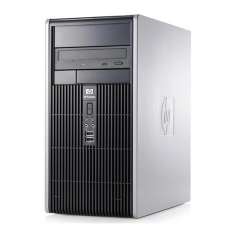
The FW-UL6W provides the hardware platform for a FireW orks life safety system. See Figure 1.
Figure 1: FW-UL6W FireWorks workstation
The FW-UL6W uses a hardware RAID 1 hard drive array consisting of two separate hard drives. Both hard drives
store the same data. If one drive fails, the other drive continues to operate with all of the data intact.
The FW-UL6W is suitable for use as:
•A workstation in a FireWorks stand-alone life safety network
•A client workstation in a FireWorks nonredundant life safety network
•A client or witness server in a FireWorks redundant life safety network
•The communication transmission medium between VESDA detectors and EST3/EST3X life safety systems.
For releasing service applications, the FW-UL6W may not control, manipulate, or display any releasing device
service features.
•A Firefighter Smoke Control Station (FSCS)
•Building System Information Unit (BSIU)

Chapter 1: Introduction
P/N 3102213-EN • REV 006 • ISS 18FEB19 3
Figure 2: Typical stand-alone life safety network
(1) FW-UL6W
(2) System event printer (if required)
(3) FireWorks nodes (125 max.)
(4) FireWorks remote clients (15 max.)
Figure 3: Typical nonredundant life safety network
(1) FW-UL6S
(2)
System event printer (if required)
(3) FW-UL6W client workstations (50 max.)
(4) FireWorks nodes (125 max.)
(5) FireWorks remote clients (15 max.)
Figure 4: Typical redundant life safety network
(1) FW-UL6S (primary server)
(2)
System event printer (if required)
(3)
FW-UL6S (backup server)
(4) FW-UL6W (witness)
(5) FW-UL6W client workstations (50 max.)
(6) FireWorks nodes (125 max.)
(7) FireWorks remote clients (15 max.)

Chapter 1: Introduction
4 P/N 3102213-EN • REV 006 • ISS 18FEB19
Software product options
Table 1 lists the software products that you can install on FW-UL6W workstations. Software products are ordered
and installed separately.
Access to the software products is controlled by a software key that has been activated with your personal
initialization numbers (PINs).
Table 1: FireWorks software product descriptions
Product
Description
FW
-CGSUL [1] Stand-alone FireWorks software with command and control features (UL Listed).
FW-CGS [2]
Stand-alone FireWorks software without command and control features.
FW
-DARCOM Digital alarm receiver software for displaying Contact ID or SIA 4/2 formatted events
from any fire alarm or security control panel. Requires a compatible digital alarm
communicator receiver (DACR).
FW-IPMON1000
Digital alarm receiver software for displaying Contact ID formatted events from up to
1,000 iO series fire alarm control panels.
FW-1S [3]
Display system information on one remote client computer connected to the Ethernet
network.
FW
-4S [3] Display system information on up to five remote computers connected to the Ethernet
network. You must activate FW-1S before you can activate FW-4S.
FW-10S [3]
Display system information on up to 15 remote computers connected to the Ethernet
network. You must activate FW-1S and FW-4S before you can activate FW-10S.
FW-HSSD5
Allows up to five FW-HSSX1 (VESDA) node connections.
FW-HSSD20
Allows up to 20 FW-HSSX1 (VESDA) node connections.
FW-FAST
Automatically populate device maps with device information from AutoCAD files.
FW-NCZZFP [4]
Optional client workstation software for nonredundant network systems (50 clients max.).
FW-RCZZFP [4]
Optional client workstation software for redundant network systems (50 clients max.).
[1] UL Listed when installed on an FW-UL6S or on an FW-UL6W.
[2] Not UL Listed.
[3] The FireWorks software installed on the workstation and the Remote Client software installed on the remote
computer must be the same version number.
[4] ZZ equals the number of clients supported.

Chapter 1: Introduction
P/N 3102213-EN • REV 006 • ISS 18FEB19 5
Front panel features
Figure 5shows the features found on the front panel of the FW-UL6W.
Figure 5: Front panel features
(1) ON/OFF key switch
(2)
USB 2.0/1.1 ports (2X)
(3)
Status LEDs (see Table 2 below)
(4) Optical drive
(5) Empty drive bays
(6) Filter assembly
(7) Fan 2
(8) Fan 1
Table 2: Status LED descriptions
LED
Description
Indicates the workstation is on
Indicates hard drive activity
Indicates internal faults reported by the watchdog card

Chapter 1: Introduction
6 P/N 3102213-EN • REV 006 • ISS 18FEB19
Rear panel features
Figure 6 shows the features found on the rear panel of the FW-UL6W.
Figure 6: Rear panel features
(1) Fan 3
(2)
PCI expansion card slots
(3) Not used
(4) I/O panel (see Figure 7)
(5) Power supply
Figure 7: FW-UL6W I/O panel
(1) Not used
(2)
Not used (2X)
(3)
DVI-I video port
(4)
RJ-45 Ethernet port (LAN 2)
(5)
RJ-45 Ethernet port (LAN 1)
(6) Not used
(7) Not used
(8) Not used
(9) USB 3.0/2.0/1.1 ports (4X)
(10) HDMI video port
(11) USB 2.0/1.1 ports (2X)

Chapter 1: Introduction
P/N 3102213-EN • REV 006 • ISS 18FEB19 7
Internal cable connections
Figure 8and Figure 9list the cable connections inside the FW-UL6W.
For additional information, see FW-PCWD6 Replacement FW-UL6 Watchdog Card Installation Sheet
(P/N 3102219-EN).
Figure 8: FW-PCWD6 cable connections
(1) Not used
(2)
Not used (2X)
(3)
From front panel Trouble LED
(4) From power supply
(5) Fan cable connections (see Table 3)
(6) No connection
(7) From motherboard COM3 connector (see Figure 9)
Table 3: FW-PCWD6 cable connections
FW
-PCWD6
FW-UL6W
Switch setting
Fan 8
Power supply fan
S1-8: ON
Fan 7
Not used S1-7: OFF
Fan 6
Not used
S1-6: OFF
Fan 5
CPU fan S1-5: ON
Fan 4
Not used
S1-4: OFF
Fan 3
Rear fan S1-3: ON
Fan 2
Front right fan
S1-2: ON
Fan 1
Front left fan S1-1: ON
(5)
(6)(7)
(3)
Fan 7
Fan 6
Fan 8
Fan 5
Fan 4
Fan 3
Fan 2
Fan 1
S1
JP9
JP10
JP11
X5
X2 (PWR)
JP5
JP6
JP8
ISP1
COM PORT
(4)(1) (2)

Chapter 1: Introduction
8P/N 3102213-EN • REV 006 • ISS 18FEB19
Figure 9: FW-UL6W motherboard cable connections
(1) From power supply
(2)
Memory slots (32 GB installed)
(3)
From FW-PCWD6 COM PORT connector
(4)
From power supply
(5)
From Drive 0
(6) From Drive 1
(7) From front panel USB ports
(8) From front panel Power LED
(9) From front panel ON/OFF key switch
(10) From front panel Hard Drive LED
(11) Expansion slots for option cards
(12) FW-PCWD6 card slot (FW-PCWD6 card installed)

Chapter 1: Introduction
P/N 3102213-EN • REV 006 • ISS 18FEB19 9
Compatible monitors, option cards, and other accessories
Table 4 and Table 5list the compatible monitors, option cards, and other accessories that you can use with the
FW-UL6W.
Table 4: Workstation accessories
Model
Description
FW-19LCDWTS
19-inch widescreen LCD monitor with a base, a capacitive USB touch screen,
and built-in speakers
FW
-22LCDW TS 22-inch widescreen LCD monitor with a base, a capacitive USB touch screen,
and built-in speakers
FW-42LCDWTS
42-inch widescreen LCD monitor with a surface acoustic wave (SAW) USB
touch screen
FW-PCWD6
Replacement FW-UL6 watchdog card
FW-SP4I
Four-port, optically-isolated serial card
FW-UL6CC1
Rear panel cable cover
FW-UL6SSSD500GB
Replacement blank solid state hard drive for FW-UL6 workstations/servers
FW-FILTER
Replacement filter
PT-1S
System event printer
MN-COM1S
RS-232 to Ethernet interface module
MN-FVPN
VoIP encoder/decoder module
MN-NETRLY4
Network relay module
MN-TK10
10-position, 4-pole DIN rail terminal block
MN-FNS4C2F3
Ethernet switch, four copper connections and two fiber optic connections
MN-FNS8C2F3
Ethernet switch, eight copper connections and two fiber optic connections
MN-FNS18C8F3
Ethernet switch, 16 copper connections and two fiber optic connections
Bosch D6600
Digital alarm communicator receiver
FW-HSSX1
VESDA Modbus High Level Interface
MFC-A
Accessory enclosure
Table 5: Rack mounting accessories
Model
Description
RKU-61-24B
19-inch rack mount enclosure, black, 35 EIA panel spaces
FW-19LCDWRACK
Rack mount kit for 19-inch widescreen LCD monitors
FW-RACKKB
Keyboard rack mount kit (requires two EIA panel spaces)
BP1
Blank plate, 1.75 × 19 in. (requires one EIA panel space)
BP2
Blank plate, 3.50 × 19 in. (requires two EIA panel spaces)
BP3
Blank plate, 5.25 × 19 in. (requires three EIA panel space)

Chapter 1: Introduction
10 P/N 3102213-EN • REV 006 • ISS 18FEB19
Minimumsystem configurations
Proprietary Fire/Security
Note: Security listings include UL 365, UL 636, UL 1076, and UL 1610.
•FW-UL6W with FW-PCWD6, keyboard, and mouse
•UL 864 Listed compatible monitor (see Table 4)
•PT-1S system event printer (if required)
Proprietary Fire
•FW-UL6W with FW-PCWD6, keyboard, and mouse
•UL 864 Listed compatible monitor (see Table 4)
•PT-1S system event printer (if required)
•Radionics/Bosch D6600 (one per workstation)
Central Station Security
•FW-UL6W with FW-PCWD6, keyboard, and mouse
•UL 864 Listed compatible monitor (see Table 4)
•PT-1S system event printer
Local Security
•FW-UL6W with FW-PCWD6, keyboard, and mouse
•UL 864 Listed compatible monitor (see Table 4)
•PT-1S system event printer (if required)
Central Station Receiving
•FW-UL6W with FW-PCWD6, keyboard, and mouse
•UL 864 Listed compatible monitor (see Table 4)
•PT-1S system event printer (if required)
•Radionics/Bosch D6600 (one per workstation)
Em e rge ncy S ignali ng
•FW-UL6W with FW-PCWD6, keyboard, and mouse
•UL 864 Listed compatible monitor (see Table 4)
•PT-1S system event printer (if required)
•Radionics/Bosch D6600 (one per workstation)
Building System Information Unit (BSIU)
•FW-UL6W with FW-PCWD6, keyboard, and mouse
•UL 864 Listed compatible monitor (see Table 4)
•PT-1S system event printer (if required)
Note: An ITE UL Listed monitor may be connected in parallel with the UL 864 Listed compatible monitor.

Chapter 1: Introduction
P/N 3102213-EN • REV 006 • ISS 18FEB19 11
Specifications
Operating system
Windows 7 Professional SP1, 64-bit
Processor
Intel Core i7
Memory
32 GB (not expandable)
Hard drive
500 GB (unformatted)
Optical drives
1
Video ports
2 (1 HDMI, 1 DVI-I)
Universal Serial Bus
Ports (USB) ports
Front
Rear
2 USB 2.0/1.1 ports
4 USB 3.0/2.0/1.1 ports, 2 USB 2.0/1.1 ports
Ethernet ports
2 10/100/1000 Mbps, RJ-45
Ser
ial ports [1] 8 (optically isolated)
Watchdog card
Yes (FW-PCWD6)
ON/OFF key switch
Yes
Status LEDs
Yes
Power
120 V, 50/60 Hz, 5 A
Dimensions (W × H × D) [2]
17.0 × 7.0 × 22.7 in. (43.2 × 17.8 × 57.7 cm)
Operating environment
Temperature
Relative humidity
32 to 120°F (0 to 49°C)
0 to 93% noncondensing
[1] Requires two FW-SP4I cards, ordered separately. Each FW-SP4I card provides four serial ports.
[2] Add 5.5 in. (14.0 cm) to the depth if an FW-UL6CC1 is installed.

Chapter 1: Introduction
12 P/N 3102213-EN • REV 006 • ISS 18FEB19
This manual suits for next models
1
Table of contents
Other Edwards Desktop manuals

