Edwards AS366 User manual
TONE
1.
2.
3.
4.
5.
6.
7.
8.
9.
10.
11.
12.
13.
14.
15.
16.
17.
18.
19.
20.
21.
22.
23.
24.
25.
26.
27.
28.
29.
30.
31.
32.
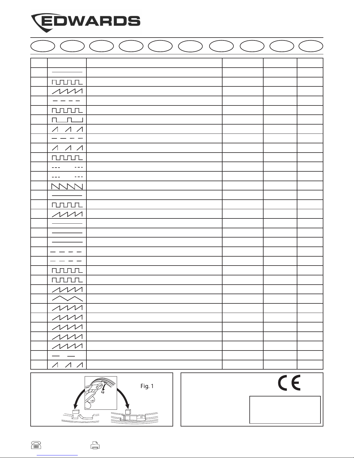
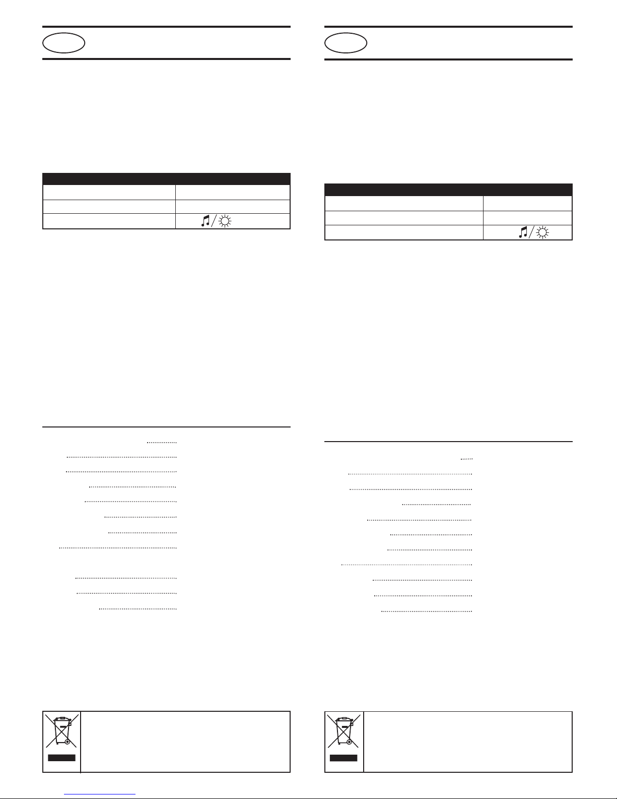
TONE TYPE TONE DESCRIPTION/ APPLICATION
970Hz
800Hz/970Hz @ 2Hz
800Hz – 970Hz @ 1Hz
970Hz 1s OFF/1s O
970Hz, 0.5s/ 630Hz, 0.5s
554Hz, 0.1s/ 440Hz, 0.4s (AF OR F S 32 001 )
500 1200Hz, 3.5s/ 0.5s OFF (NEN 2575:2000 Dutch Slow Whoop)
420Hz 0.625s O /0.625s OFF (Australia AS1670 Alert tone)
500 – 1200Hz, 0.5s/ 0.5s OFF x 3/1.5s OFF ( AS1670 Evacuation)
550Hz/440Hz @ 0.5Hz
970Hz, 0.5s O /0.5s OFF x 3/ 1.5s OFF (ISO 8201 )
2850Hz, 0.5s O /0.5s OFF x 3/1.5s OFF (ISO 8201)
1200Hz – 500Hz @ 1Hz (DI 33 404)
400Hz
550Hz, 0.7s/1000Hz, 0.33s
1500Hz – 2700Hz @ 3Hz
750Hz
2400Hz
660Hz
660Hz 1.8s O /1.8s OFF
660Hz 0.15s O /0.15s OFF
510Hz, 0.25s/ 610Hz, 0.25s
800/1000Hz 0.5s each (1Hz)
250Hz – 1200Hz @ 12Hz
500Hz – 1200Hz @ 0.33Hz
2400Hz – 2900Hz @ 9Hz
2400Hz – 2900Hz @ 3Hz
800Hz – 970Hz @ 100Hz
800Hz – 970Hz @ 9Hz
800Hz – 970Hz @ 3Hz
800Hz, 0.25s O /1s OFF
500Hz – 1200Hz, 3.75s/0.25s OFF (AS2220)
DIP SWITCH
O-O-O-O-O
O-O-O-O-I
O-O-O-I-O
O-O-O-I-I
O-O-I-O-O
O-O-I-O-I
O-O-I-I-O
O-O-I-I-I
O-I-O-O-O
O-I-O-O-I
O-I-O-I-O
O-I-O-I-I
O-I-I-O-O
O-I-I-O-I
O-I-I-I-O
O-I-I-I-I
I-O-O-O-O
I-O-O-O-I
I-O-O-I-O
I-O-O-I-I
I-O-I-O-O
I-O-I-O-I
I-O-I-I-O
I-O-I-I-I
I-I-O-O-O
I-I-O-O-I
I-I-O-I-O
I-I-O-I-I
I-I-I-O-O
I-I-I-O-I
I-I-I-I-O
I-I-I-I-I
dBA @ 1m
99
100
100
99
99
97
99
96
98
97
98
94
99
95
98
104
99
106
96
96
96
98
100
98
99
101
104
100
99
100
99
99
mA
21
20
20
14
19
13
16
9
10
14
12
21
17
13
17
34
18
45
17
12
11
15
21
13
17
40
40
20
20
20
8
17
E 54-3:2001+A1
Technical Data Document 18-186215
Fire Alarm Device - Sounder
Type A: For indoor use
(Shallow Base)
Type B: For outdoor use
(Deep Base)
0832
06
AS366 & AS367 Sounder-Beacon Range
In tallation In truction
AS366: 0832-CPD-0552
AS367: 0832-CPD-0553
AS366W 0832-CPD-0554
AS367W 0832-CPD-0555
FR NL
EN DE ES PT IT PL SE DK
Issue 2 (July 2010) 18-186754-2
Copyright © 2010 UTC Fire & Security BV. All Rights Reserved
UTC Fire & Security BV.
Kelvinstraat 7, L- 6003DH Weert, The etherlands.
+31 495 45 67 35 +31 495 55 00 42

Ins alla ion Manual
Ins alla ion
If required, the mechanism for locking the sounder to the base
can be activated by removing the thin section of plastic shown in
Fig. 1 with side cutters or a similar tool. To open a locked head,
remove the small rubber bung from the hole on the side of the
sounder, insert a tool into the hole and depress the clip whilst
twisting the head. The O-ring and bung must be re-fitted to
maintain the weatherproofing.
Wiring
The sounder and beacon 0V terminals can be linked together for
simultaneous control of sound and light using a 2-core connection.
A separate earth terminal is provided on the deep base for connecting
the screen or functional earth. On the shallow base, terminal 5
can be used for this purpose.
Tone Selec ion and Volume Con rol
a) The tone is selected using the 5 way dipswitch on the bottom of
the sounder head. Refer to the table overleaf for details of the
available tones and the switch settings required to select them.
b) The sound output of the unit can be reduced by adjusting the
potentiometer on the bottom of the sounder.
Technical Specifica ion
Supply Voltage Range 17 - 60V DC
Current Sounder: 4 - 45mA*
Beacon: 5mA
Peak Sound Level 94 - 106 dBA at 1m*
Number of Tones 32
Frequency Range 400 - 2850 Hz*
Operating Temperature -25˚C to + 70˚C
Casing High Impact Polycarbonate
IP Rating IP21
IP65 (with deep base)
Synchronisation Automatic
*depends on selected tone and input voltage. See tone table for details.
EN54-3 certified on tones 1,2,3,4,5,6,7 & 13
Line Terminal Marking
Common Positive Supply IN (3) IN+
Sounder Negative Supply (2) – or CO –
Beacon Negative Supply (1)
Ins alla ionsanweisung
Ins alla ion
Um den Signalgeber im Sockel zu arretieren, ist das
Sicherungsplättchen im Gehäuse zu entfernen. Dies kann
vorsichtig mit einem Seitenschneider oder ähnlichem Werkzeug,
wie in der Abb. 1 dargestellt, herausgelöst werden. Um einen
arretierten Signalgeberkopf aus dem Sockel zu entnehmen, ist
zunächst die weiße Schutzkappe am Kopf herauszuziehen und
durch die Öffnung, mit einem schmalen Schraubendreher, den
innen liegenden Verschlussbügel aus der Arretierungsposition zu
drücken. Um die Schutzklasse zu erhalten, ist die Schutzkappe
und der O-Ring wieder einzusetzen.
Verdrah ung
Die 0V Klemmen des akustischen und optischen Signals sollten
zusammengeführt werden, um beide Signale in einem
Zweileitersystem gemeinsam zu steuern.
Eine zusätzliche Klemme steht im PG-Sockel zur Verfügung, um
PE oder die Abschirmung auflegen zu können. Im flachen
ontagesockel kann Klemme 5 zu diesem Zweck genutzt werden.
Tonauswahl und Regulierung der Lau s ärke
a) Der Ton ist über den 5fach-DIP-Schalter, der sich am Gehäuseboden
befindet, zu selektieren. Die zur Verfügung stehende Töne und
die entsprechenden Schalterkombinationen, sind auf der
Folgeseite gelistet.
b) Die Lautstärke läßt sich über das Potentiometer am Gehäuseboden
einstellen.
Technische Spezifika ionen
Betriebsspannung 17 – 60 V DC
Stromaufnahme Akustischer: 4 – 45 mA
Optischer Signalgeber: 5mA
ax. Lautstärkepegel 94 – 106 dBA bei 1m*
Anzahl Töne 32
Frequenzbereich 400 – 2850 Hz*
Bemessungsgrundlage Dauerton
Betriebstemperatur -25 bis + 70 °C
Gehäuse schlagbeständiges Polykarbonat
Schutzklasse IP21
IP65 (mit tiefem Sockel)
Synchronisation Automatisch
*je nach gewähltem Ton und Eingangsspannung. Ausführliche Informationen siehe
Tontabelle. EN54-3 zertifiziert nur für Töne 1,2,3,4,5,6,7 und 13.
Anschluss Klemme
Common Versorgung + (17 bis 60 V DC) (3) IN+
Versorgung – (0 V) (2) – oder CO –
Optisches Signal: Versorgung – (0 V) (1)
EN DE
The European directive “Waste Electrical and Electronic Equipment” (WEEE)
aims to minimise the impact of electrical and electronic equipment waste on
the environment and human health. To conform with this directive, electrical
equipment marked with this symbol must not be disposed of in European
public disposal systems. European users of electrical equipment must now
return end-of-life equipment for disposal. Further information can be found on
the following website: http://www.recyclethis.info/.
Das Ziel der EG-Richtlinie über Elektro- und Elektronik-Altgeräte ist, Umwelt-und
Gesundheitsschäden durch Elektro- und Elektronik-Altgeräte so gering wie
möglich zu halten. Um diese Richtlinie einzuhalten, dürfen Elektrogeräte, die mit
diesem Symbol gekennzeichnet sind, nicht in den öffentlichen europäischen
Entsorgungssystemen entsorgt werden. Europäische Benutzer von Elektrogeräten
müssen ab sofort Altgeräte zur Entsorgung zurückgeben.
Nähere Informationen hierzu finden Sie auf der folgenden
Website: http://www.recyclethis.info/.
Notice d'inst uctions
Installation
Pour activer le verrouillage de la sirène à sa base, il faut enlever la
fine plaque de plastique comme indiqué sur le dessin 1 avec un
cutter. Pour déverrouiller la base, enlever l'insert blanc situé sur
le côté, insérer un outil dans le trou pour appuyer sur le verrou
tout en faisant pivoter la sirène. Le joint torique et l'insert doivent
être replacé pour maintenir l'étanchéité.
Câblage
Le commun (0 Volts) de la sirène et du feu à éclats peuvent être
interconnectés pour un déclenchement simultané par une seule
paire de fils.
Les ornes 4 sur la ase longue et 5 sur la ase courte permet
de connecter l'écran ou la terre.
Sélection de tonalité et contrôle du volume
a. La sirène est programmée sur le son AFNOR NF S32-001.
D'autres sons peuvent être sélectionnés en utilisant les 5
microcontacts de la sirène. Voir le ta leau de choix des sons
pour plus de détails sur les sons disponi les et la position des
microcontacts correspondante.
. Contrôle du volume non disponi le lorsque la sirène est utilisée
en son AFNOR NF S32-001 (554Hz, 0.1s/440Hz, 0.4s).
Spécification technique
Tension admissible 17 à 60 Vcc
Consommation Sirène : de 4 à 45 mA*
Feu à éclats : 5 mA
Puissance sonore maximum 94 à 106 dB(A) à 1m*
ombre de sons 32
Gamme de fréquence De 400 à 2850 Hz*
Température de fonctionnement De - 25°C à + 70°C
Matière Polycarbonate résistant
au choc
Degré d'étanchéité IP21
IP65 (avec base longue)
Synchronisation Automatique
* Variable selon les sons et les tensions. Voir tableau des sons pour plus
d'informations. Certifié selon la E 54-3 pour les tons 1, 2, 3, 4, 5, 6, 7 et 13.
Alimentation Bo nie
+ Alimentation (3) I +
- Alimentation (0 Vcc) (2) –ou COM –
Feu à éclats- Alimentation (1)
Montageinst ucties
Montage
Indien nodig kan het mechanisme om het alarm aan de basis te
vergrendelen worden geactiveerd door het verwijderen van het
dunne stukje plastic met een tang of vergelijkbaar gereedschap
zoals aangegeven in Fig. 1. Om een vergrendelde kop te openen:
verwijder de kleine witte stop uit het gat aan de zijkant van het
alarm, steek een schroevendraaier o.i.d. in het gat en druk het
lipje in terwijl u de kop draait. De o-ring en de stop moeten
worden teruggeplaatst om de waterdichtheid te behouden.
Bedrading
De 0 V contacten van het alarm en het baken kunnen aan elkaar
worden gekoppeld voor simultane bediening van geluid en licht
met een twee-aderige aansluiting.
Op de hoge basis is een aparte aardaansluiting aanwezig voor
het aansluiten van het scherm of de aarde. Op de lage basis kan
uitgang 5 hiervoor gebruikt worden.
Toonkeuze en volumebediening
a) De toon wordt geselecteerd met de vijfweg-instelschakelaar op de
onderkant van de alarmkop. Kijk op de tabel aan ommezijde
voor gegevens over de beschikbare tonen en de schakelaarin
stellingen om deze te selecteren.
b) De geluidsuitvoer van de eenheid kan verminderd worden door
het aanpassen van de potentiometer aan de onderkant van het
alarm.
Technische specificaties:
Spanningsbereik 17 - 60V gelijkstroom
Stroomsterkte Alarm: 4 - 45mA*
Baken: 5mA
Geluidsniveaupiek 94 - 106 dBA op 1m*
Aantal tonen 32
Frequentiebereik 400 - 2850 Hz*
Gebruikstemperatuur - 25°C tot +70°C
Behuizing Slagvast polycarbonaat
IP waarde IP21
IP65 (ALLEE met hoge basis)
Synchronisatie Automatisch
*afhankelijk van de gekozen toon en het voltage. Zie de toontabel voor details.
Door de E 54-3 gecertificeerd, alleen tonen 1,2,3,4,5,6,7 en 13
Lijn Contact ma ke ing-
Common Gewone positieve voeding I (3) I +
egatieve voeding alarm (2) – of COM –
egatieve voeding waarschuwingsbaken (1)
FR NL
La directive européenne " Déchets d'Equipements Electriques et Electroniques "
(DEEE) a pour ut de minimiser l'impact des déchets électriques et électroniques
sur l'environnement et la santé humaine. Conformément à cette directive, tout
équipement électrique disposant de ce sym ole ne doit pas être jeté dans les
systèmes d'évacuation des déchets pu lics européens. Les utilisateurs
européens d'équipement électrique doivent désormais renvoyer tout équipement
électrique en fin de vie pour évacuation. Vous trouverez de plus amples
informations sur le site We suivant : http://www.recyclethis.info/.
De Europese richtlijn "Afgedankte elektrische en elektronische apparatuur"
(AEEA) is er op gericht om de impact van het afval van elektrische en
elektronische apparatuur op het milieu en de gezondheid van de mens te
minimaliseren. Om aan deze richtlijn te voldoen, moet elektrische apparatuur
die met dit sym ool gemarkeerd is, niet worden verwerkt in Europese open are
afvalsystemen. Europese ge ruikers van elektrische apparatuur dienen nu
apparatuur aan het einde van de levensduur aan te ieden voor
verwerking.Meer informatie vindt u op de volgende we site:
http://www.recyclethis.info/.
Instrucciones de Instalación
Instalación
Active el mecanismo de seguridad si esto fuera necesario, para
evitar que la sirena pueda ser desconectada de la base. ara
hacer esto, corte el cacho de plástico que le mostramos en la Fig. 1.
Una sirena que haya sido bloqueada, solo se puede desbloquear
quitando el pequeño tapón situado en el lateral e insertando una
pequeña varilla para presionar el mecanismo de bloqueo.
Debemos asegurar que la arandela y el tapón están colocados
para asegurar la resistencia a intemperie.
Cableado
ara un funcionamiento simultaneo de la luz de xenón y la sirena
en un sistema de dos cables, los terminales (0V) deben estar
unidos.
Selección de Tono y Control de Volumen
a) El tono se selecciona usando el interruptor de 5 posiciones
situado en la parte inferior de la sirena. Mire la tabla adjunta
para ver detalles de los tonos disponibles y las posiciones del
interruptor para seleccionar el tono requerido.
b) El volumen de la sirena se puede ajustar usando el
potenciómetro situado en la parte inferior de la sirena.
Especificaciones Técnicas:
Voltaje de Alimentación 17 - 60V DC
Consumo 4 - 45mA*
Luz LED – 5mA
Máximo Nivel Sonoro 94 - 106 dBA a 1m*
Número de Tonos 32
Frecuencia 400 - 2850 Hz*
Temperatura de Funcionamiento - 25°C a + 70°C
Carcasa olicarbonato Resistente
al Fuego
Clasificación I I 21
I 65 (Con Base de Entrada
de Tubo)
Sincronización Automática
* depende del tono seleccionado y la tensión de alimentación.
Ver la tabla de tonos para los detalles. EN54-3 accreditado solamente
tonos 1,2,3,4,5,6,7 & 13.
Línea Terminal
Common ositivo IN (3) IN+
Consumo Negativo (2) –ou COM –
Conexión Negativo de la luz de Xenón (1)
ES Manual de Instalaç o
Instalaç o
Se necessário, o mecanismo para fixar o sensor à base
pode ser activado removendo a fina película de plástico
ilustrada na Fig. 1 com um alicate de corte ou uma
ferramenta semelhante. ara abrir uma cabeça bloqueada,
retire o pequeno tampão branco do orifício existente na
parte lateral do sensor, insira uma ferramenta no orifício e
carregue na mola enquanto roda a cabeça. O O-ring e o
tampão devem ser reinstalados no intuito de manter a
estanquicidade às intempéries.
Cablagem
Os terminais 0V do sensor e do farolim rotativo podem ser
interligados para um controlo simultâneo do som e da luz,
utilizando uma ligação de 2 núcleos
É fornecido um terminal terra independente na base profunda
para ligar o ecrã ou a terra funcional. Na base côncava, pode
utilizar-se o terminal 5 para este fim.
Selecç o de mensagens sonoras e controlo do volume
a) A mensagem sonora é seleccionada utilizando o comutador
DI Switch de 5 vias existente na parte inferior da cabeça do
sensor. Consulte a tabela no verso para obter detalhes sobre as
mensagens sonoras disponíveis e configurações do comutador
necessárias para as seleccionar.
b) É possível reduzir o volume de som da unidade regulando o
potenciómetro existente na parte inferior do sensor
Especificações técnicas :
Gama da tensão de alimentação 17 - 60V CC
Corrent Sensor 4 - 45mA*
Farolim rotativo 5mA
Nível sonoro de pico 94 - 106 dBA a 1m*
Número de mensagens sonoras 32
Gama de frequência 400 - 2850 Hz*
Regime ermanente
Temperatura de funcionamento - 25˚C a + 70˚C
Caixa olicarbonato de alto impacto
Classe de protecção I 21
I 65 (com base profunda)
Sincronização Automático
*depende do tom seleccionado e da tensão de entrada. ara mais informações,
consultar a tabela de tons. Certificado apenas nos tons 1,2,3,4,5,6,7 e 13
linha Marcaç o Terminal
Alimentação positiva comum IN (3) IN+
Alimentação negativa do sensor (2) –or COM –
Alimentação negativa do farolim rotativo (1)
PT
El objetivo de la directiva europea de Eliminación de e uipos eléctricos y electrónicos
(WEEE) es minimizar el impacto de la eliminación de e uipos eléctricos y
electrónicos sobre el medioambiente y la salud de las personas. Para cumplir con
esta directiva, el e uipamiento eléctrico marcado con este símbolo no deberá
desecharse en ningún sistema de eliminación europeo público. Los usuarios
europeos de e uipamiento eléctrico deberán retornar los e uipos eléctricos y
electrónicos al final de su vida útil para su eliminación. Para más información
visite el siguiente sitio Web: http://www.recyclethis.info/.
A Directiva europeia “Resíduos de E uipamentos Eléctricos e Electrónicos”
(REEE) tem como objectivo minimizar o impacto dos resíduos de e uipamentos
eléctricos e electrónicos no ambiente e na saúde humana. Para dar
cumprimento a esta Directiva, o e uipamento eléctrico ue contenha este
símbolo não deve ser eliminado nos sistemas de eliminação pública europeus.
Os utilizadores europeus de e uipamento eléctrico devem agora devolver os
e uipamentos em fim de vida para eliminação. Para mais informações,
consultar o seguinte sítio da Web: http://www.recyclethis.info/.
Istruzioni di installazione
Installazione
Se necessario, è possibile attivare il meccanismo di bloccaggio del
segnalatore acustico alla base rimuovendo la sottile linguetta di
plastica illustrata nella Fig. 1 con un tronchesino o un attrezzo
simile. Per aprire una testina bloccata, rimuovere il piccolo tappo
bianco dal foro laterale del segnalatore acustico, inserire un
attrezzo nel foro e premere il fermo svitando la testina. La
guarnizione ad anello e il tappo devono essere riposizionati per
mantenere la resistenza alle intemperie.
Cablaggio
È possibile collegare tra loro i terminali 0V del segnalatore acus-
tico e del segnalatore luminoso per il controllo simultaneo del suono
e della luce usando un collegamento a due fili.
La base profonda è dotata di un terminale di terra separato per il
collegamento dello schermo o della terra funzionale. Sulla base
superficiale, allo stesso scopo è possibile usare il terminale 5.
Selezione toni e Controllo olume
a) Il tono viene selezionato usando un commutatore a 5 vie situato
sulla parte inferiore della testina del segnalatore acustico.
Consultare la tabella a tergo per informazioni sui toni disponibili
e sulle impostazioni del commutatore necessarie per selezionarli.
b) È possibile ridurre l’emissione di suono dell’unità regolando il
potenziometro sulla parte inferiore del segnalatore.
Specifiche tecniche:
Gamma tensione di alimentazione 17 - 60V CC
Corrente Segnalatore acustico: 4 - 45mA*
Segnalatore luminoso: 5mA
Livello di picco del suono 94 - 106 dBA a 1m*
umero di toni 32
Gamma di frequenza 400 - 2850 Hz*
Temperatura di esercizio - 25°C/ + 70°C
Alloggiamento Policarbonato ad alto impatto
Classe di IP IP21
IP65 (SOLO con base profonda)
Sincronizzazione Automatica
*dipende dal tono selezionato e dalla tensione di ingresso. Per infor
mazioni dettagliate, consultare la tabella dei toni. Certificazione E 54-3
solo sui toni 1,2,3,4,5,6,7 e 13.
Linea Contrassegno sui terminali
I alimentazione positiva comune (3) I +
Alimentazione negativa segnalatore acustico (2) – of COM –
Alimentazione negativa segnalatore luminoso (1)
IT Instrukcja montażu
Instalacja
W razie potrzeby mechanizm blokujący głośnik na podstawie
można uruchomić, usuwając cienką warstwę folii pokazaną na
Rys. 1 za pomocą szczypiec lub podobnego narzędzia. Aby
otworzyć zablokowaną głowicę, należy usunąć małe, białe
zamknięcie z otworu bocznego głośnika i za pomocą narzędzia
umieszczonego w otworze nacisnąć zatrzask jednocześnie
przekręcając głowicę. Pierścień „O” i zamknięcie muszą zostać
założone ponownie, aby zapewnić zabezpieczenie przed
warunkami pogodowymi.
Okablowanie
Końcówki 0V głośnika i sygnalizatora mogą zostać połączone w
celu jednoczesnego sterowania dźwiękiem i światłem za pomocą
połączenia 2-rdzeniowego
W głębokiej podstawie dostępna jest oddzielna listwa zaciskowa
dla podłączenia ekranu lub zera roboczego. W przypadku płytkiej
podstawy do tego celu służy zacisk 5.
Wybór tonu i regulacja głośności
a) Ton wybierany jest za pomocą 5 pozycyjnego przełącznika dipswitch
znajdującego się na spodzie głowicy głośnika. W celu uzyskania
informacji dotyczących dostępnych tonów i odpowiadających
im ustawień przełączników, należy zapoznać się z tabelą na
odwrocie.
b) Dźwięk wyjściowy urządzenia można zredukować za pomocą
potencjometru znajdującego się na spodzie głośnika.
Dane techniczne:
Zakres napięcia zasilania 17 - 60V DC
Prąd Głośnik: 4 - 45mA*
Sygnalizator: 5mA
Szczytowe natężenie dźwięku 94 - 106 dBA at 1m*
Ilość tonów 32
Zakres częstotliwości 400 - 2850 Hz*
Temperatura pracy - 25˚C to + 70˚C
Obudowa Wytrzymałego poliwęglanu
Oznaczenie IP IP21
IP65 (z głęboką podstawą)
Synchronizacja Automatyczna
*zależy od wybranego tonu i napięcia wejściowego. W celu uzyskania
szczegółowych informacji należy zapoznać się z informacjami podanymi w tabeli
tonów. Gwarantowane wyłącznie w przypadku tonów 1, 2, 3, 4, 5, 6, 7 i 13.
Linia Listwa zaciskowa
Dodatnie, normalne zasilanie wejściowe I (3) I +
Ujemne zasilanie głośnika (2) –lub COM –
Ujemne zasilanie sygnalizatora (1)
PL
La Direttiva europea nota come "Waste Electrical and Electronic E uipment"
(WEEE), è volta a ridurre al minimo l'impatto sull'ambiente e sulla salute umana
provocato dallo smaltimento di apparecchiature elettriche ed elettroniche. Al
fine di garantire conformità a tale direttiva, è vietato smaltire le apparecchiature
elettriche contrassegnate da uesto simbolo nei comuni cassonetti per lo
smaltimento dei rifiuti siti in territorio europeo. Gli utilizzatori europei sono tenuti
a restituire le apparecchiature elettriche ed elettroniche al termine del loro ciclo
di vita per consentirne il corretto smaltimento.Per ulteriori informazioni, visitare
il seguente indirizzo: http://www.recyclethis.info/.
Dyrek ywa europejska „W sprawie zuży ego sprzę u elek rycznego i
elek ronicznego” (WEEE) ma na celu zmniejszenie wpływu odpadów sprzę u
elek rycznego i elek ronicznego na środowisko i zdrowie człowieka. Aby
spełnić wymagania dyrek ywy, sprzę elek ryczny oznaczony ym symbolem
nie może być usuwany razem z odpadami komunalnymi. Obecnie uży kownicy
sprzę u elek rycznego na erenie Europy po zakończeniu uży kowania
sprzę u muszą zwracać go w celu jego u ylizacji. Szczegółowe informacje
podano w wi rynie in erne owej: h p://www.recycle his.info/.
Installationsmanual
Installation
Om så behövs, kan mekanismen för att låsa summern vid basen
aktiveras genom att avlägsna den tunna plastbiten, såsom visas i
Fig. 1, med en sidavbitare eller liknande. För att öppna ett låst
huvud, avlägsna den lilla vita proppen från hålet på sidan av
summern, för in ett verktyg i hålet och tryck ned klämman medan
huvudet vrids. O-ringen och proppen måste sättas tillbaka för att
bibehålla väderskyddet
Koppling
Summerns och blinkljusets utklämmor kan sammankopplas för
samtidig reglering av ljud och ljus med användning av en tvåådrig
anslutning
En separat jordklämma finns på den djupa basen för att anslutas
till skärmen eller funktionsjord. På den låga basen, kan klämma 5
användas för detta ändamål.
Tonval och vol mkontroll
a) Tonen ställs in med en femvägs dipswitch på summerhuvudets
undersida. Se tabellen på nästa sida för uppgifter om tillgängliga
toner och switchinställningar som krävs för att välja dem.
b) Ljudeffekten för enheten kan minskas genom att justera
potentiometern på summerns undersida
Teknisk specifikation
atningsspänningsområde 17 - 60V likström
Ström Summer: 4 - 45mA*
Blinkljus: 5mA
Toppljudnivå 94 - 106 dBA vid 1m*
Antal toner 32
Frekvensområde 400 - 2850 Hz*
Arbetstemperatur -25˚C to + 70˚C
Hus Hus av extra slagtåligt
polykarbonat
IP-värde IP21
IP65 ( med djup bas )
Synkronisering Automatisk
*beroende på vald ton och inspänning. Se tontabellerna för uppgifter.
Enbart kalibrerad för toner 1,2,3,4,5,6,7 & 13
Ledning Kabelfäste
Gemensamt positivt nät IN (3) IN+
Summer negativt nätgativ nät (2) – eller CO –
Blinkljus negativt nät (1)
Installationsanvisninger
Installation
Om nødvendigt kan mekanismen for aflåsning af lyd alarmen til
underlaget aktiveres ved at fjerne det tynde plastik lag, som vist
på fig. 1; dette kan gøres med sideskærere eller et lignende
værktøj. For at åbne et låst hoved, fjern den lille hvide spunstap
fra hullet på lyd alarmens side, og sæt et værktøj ind i hullet og
tryk klemmen ned mens hovedet drejes. O-ringen og spunstappen
skal genmonteres for at bevare vejrtætningen.
Trådføring
Lyd alarmens og blinklysets 0V klemmer kan sammenkobles for
sideløbende kontrol af lyd og lys med en totrådet forbindelse.
Der findes en separat jordklemme på det dybe underlag for
tilslutning af skærmen eller den funktionelle jordklemme. På det
flade underlag, kan klemme 5 bruges til dette formål
Valg af tone og l dkontrol
a) Tonen vælges med en femvejs nedblænder, som sidder på
bunden af lyd alarmens hoved. Der henvises til tabellen på
næste side for nærmere oplysninger om tilgængelige toner og
hvilke omkoblerindstillinger der skal vælges.
b) Enhedens lydeffekt kan reduceres ved at justere spændingsmåleren
på bunden af lyd alarmen.
Teknisk specifikation:
Strømforsyningens spændingsområde 17 – 60 V DC
Strøm Aktuel lyd alarm: 4 – 45 mA
Blinklys : 5mA
aksimalt lydniveau 94 - 106 dBA ved 1m*
Antal toner 32
Frekvensområde 400 – 2850 Hz*
Driftstemperatur - 25˚C to + 70˚C
Hus Slagfast hus af polykarbonat
IP kapacitet IP21
IP65 (med dybt underlag)
Synkronisering Automatisk
*afhænger af den valgte tone og indgangsspænding. Se tone tabellen for nærmere
oplysninger. Kun certificerede toner 1,2,3,4,5,6,7 & 13
Ledning Klemme Marking
Almindelig positiv strømforsyning IN (3) IN+
Lyd alarmens negative strømforsyning (2) – elle CO –
Blinklys negativ strømforsyning (1)
SE DK
Det europei ka direktivet om avfall om utgör av eller innehåller elektri ka eller
elektroni ka produkter (WEEE) har i yfte att minimera verkningen av elektri kt
och elektroni kt avfall på miljö och männi kor häl a. För att följa detta direktiv,
får elektri k utru tning märkt med denna ymbol inte avfall hantera i europei ka
kommunala avfall y tem. Europei ka brukare av elektri k utru tning må te
numera lämna tillbaka uttjänad utru tning för avfall hantering.
Ytterligare information finn på följande hem ida: http://www.recyclethi .info/.
Det europæi ke direktiv “Wa te Electrical and Electronic Equipment” (WEEE)
at er på at reducere påvirkningen af affald fra elektri k og elektroni k ud tyr
på miljøet og menne ker undhed. For at overholde dette direktiv, må
elektri k ud tyr med dette ymbol ikke ka ere i offentlige europæi ke
affald y temer. Europæi ke brugere af elektri k ud tyr kal returnere udtjent
ud tyr for ka ering. Yderligere information finde på følgende web ide:
http://www.recyclethi .info/.
This manual suits for next models
1
Table of contents
Popular Marine Equipment manuals by other brands

Geometrics
Geometrics G-882 Operation manual

Leroy-Somer
Leroy-Somer Nidec LSA PMR 320 Installation and Maintenance

Teledyne
Teledyne Everywhereyoulook SENTINEL V Deployment guide

Raymarine
Raymarine A series installation instructions

Furuno
Furuno FCV-295 Operator's manual

Konsberg
Konsberg EM 124 installation manual


Furuno
Furuno FA-150 Operator's guide

Marport
Marport Trawl Explorer Service manual

urmet domus
urmet domus 1043 installation manual

DIGITAL YACHT
DIGITAL YACHT AISnet Internet Base Station Installation & quick start guide

Dual
Dual MXDM66 Installation & owner's manual

Sleipner
Sleipner SH400 installation guide