EEC 6900S Series User manual

6900S Series
6905S/6910S/6920S/6930S/6950S
AC Power Source
User Manual
E1.01


WARRANTY
EEC certifies that the instrument listed in this manual meets or exceeds published manufacturing
specifications. This instrument was calibrated using standards that are traceable to the National
Institute of Standards Taiwan.
Your new instrument is warranted to be free from defects in workmanship and material for a
period of (2) year from date of shipment. During the warranty period, you must return the
instrument to EEC or branch offices or its authorized distributor for repair. EEC reserves the right
to use its discretion on replacing the faulty parts or replacing the assembly or the whole unit.
Under the following circumstances, EEC will void your warranty.
•Operate under non-normal, contrived omission, or accidental calamity (including, temblor,
floods, rebellion, and fire etc.)
•Any non-authorized modifications, tampering or physical damage.
•Elimination of any connections in the earth grounding system or bypassing any safety
systems.
•Use of non-authorized parts in the repair of this instrument. Parts used must be parts that
are recommended by EEC as an acceptable specified part.
This warranty does not cover accessories not out of EEC manufacture.
Except as provided herein, EEC makes no warranties to the purchaser of this instrument and all
other warranties, express or implied (including, without limitation, merchantability or fitness for
a particular purpose) are hereby excluded, disclaimed and waived.
EEC recommends that your instrument need to be calibrated on every twelve month cycle.

Modification history
Date
Version
Content
2017/5
C1.00
First edition

CONTENT
CHAPTER 1. INTRODUCTION ......................................................................................1
1.1 Product Marking Symbols .....................................................................................................1
1.2 Safety Precaution ..................................................................................................................1
1.3 Service and Maintenance......................................................................................................1
CHAPTER 2. GETTING STARTED ..................................................................................3
2.1 Unpacking and Inspection .....................................................................................................3
2.2 Preparation For Use...............................................................................................................3
2.2.1 Power Requirements....................................................................................................3
2.2.2 Power Cable..................................................................................................................3
2.3 Environmental Conditions.....................................................................................................4
CHAPTER 3. SPECIFICATIONS......................................................................................5
3.1 Specification ..........................................................................................................................5
3.2 Front Panel Description.........................................................................................................9
3.3 Rear Panel Description ........................................................................................................12
CHAPTER 4. MANUAL OPERATION...........................................................................14
4.1 Manual Operation ...............................................................................................................14
4.2 System Parameter Setup .....................................................................................................16
4.3 Displayed Messages.............................................................................................................18
CHAPTER 5. CALIBRATION PROCEDURE...................................................................20
5.1 Calibration Procedure..........................................................................................................20
CHAPTER 6. SERVICE AND MAINTENANCE..............................................................23


1
CHAPTER 1. INTRODUCTION
1.1 Product Marking Symbols
Product will be marked with this symbol when it is necessary to refer to the
operation and service manual in order to prevent injury or equipment damage.
Product will be marked with this symbol when hazardous voltages may be present.
1.2 Safety Precaution
•This product and its related documentation must be reviewed with full
acknowledgement on safety markings and instructions before operation.
•Before applying power, verify that the instrument is set to the correct line voltage and
installed the correct fuse.
•When using an oscilloscope to measure DUT waveform, please refer description below to
avoid DUT, instrument and oscilloscope damages. When the output of AC source has N-G
or L-G shorted, customer must use differential isolation type of oscilloscope probe or
using isolated oscilloscope.
To prevent accidental injury or death, these safety procedures must be strictly observed
when handling and using the test instrument.
1.3 Service and Maintenance
User Service
To prevent electric shock do not remove the instrument cover. There are no user serviceable
parts inside. Routine maintenance or cleaning of internal parts is not necessary. Any
external cleaning should be done with a clean dry or slightly damp cloth. Avoid the use of
cleaning agents or chemicals to prevent any foreign liquid from entering the cabinet through
ventilation holes or damaging controls and switches, also some chemicals may damage plastic
parts or lettering. Any replacement cables and high voltage components should be acquired
directly from EEC or its distributor.
Service Interval
The instrument must be returned at least once a year to an EEC authorized service center for
calibration and inspection of safety related components. EEC will not be held liable for injuries

2
suffered if the instrument is not properly maintained and safety checked annually.
User Modifications
Unauthorized user modifications will void your warranty. EEC will not be responsible for any
injuries sustained due to unauthorized equipment modifications or use of parts not specified
by EEC. Instruments returned to EEC with unsafe modifications will be returned to their
original operating condition at the customer’s expense.

3
CHAPTER 2. GETTING STARTED
This section contains information for the unpacking, inspection, preparation for use and
storage of your EEC product.。
2.1 Unpacking and Inspection
Your instrument was shipped in a custom foam insulated container that complies with ASTM
D4169-92a Assurance Level II Distribution Cycle 13 Performance Test Sequence
If the shipping carton is damaged, inspect the contents for visible damage such as dents,
scratches, or broken display. If the instrument is damaged, notify the carrier and EEC's
customer support department. Please save the shipping carton and packing material for the
carrier’s inspection. Our customer support department will assist you in the repair or
replacement of your instrument. Please do not return your product without first notifying us.
Please retain all of the original packaging materials.
2.2 Preparation For Use
2.2.1 Power Requirements
This instrument requires a power source of 110 volts AC ± 10%, 50/60 Hz single phase or 220
volts AC ±10%, 50/60 Hz single phase. Please check the rear panel to be sure the proper
switch setting is selected for your line voltage requirements before turning your instrument
on.
Do not switch the line voltage selector switch located on the rear panel
while the instrument is on or operating. This may cause internal damage
and represents a safety risk to the operator.
2.2.2 Power Cable
Before connecting power to this instrument, the protective ground (Earth)
terminals of this instrument must be connected to the protective conductor
of the line (mains) power cord. The main plug shall only be inserted in a socket outlet
(receptacle) provided with a protective ground (earth) contact. The main terminal shall only
be connected to a connector provided with a protective ground (earth) contact. This
protective ground (earth) must not be defeated by the use of an extension cord without a
protective conductor (grounding).
!!! Please must use the Class I product to be as the load.
CAUTION
WARNING

4
2.3 Environmental Conditions
Operating Environment
Temperatures:0°- 40°C (32-104F)
Relative humidity: 20% - 80%
Altitude: 2,000 meters (6,560 inches)
Please keep unimpeded around the units for good ventilation and convenient maintenance.
The instrument should also be protected against temperature extremes which may cause
condensation within the instrument.
Storage and Shipping Environment
This instrument may be stored or shipped in environments with the following limits:
Temperature......................... -40°to +55°C
Altitude: …………………… 7,620 meters (25,000 inches)
The instrument should also be protected against temperature extremes, which may cause
condensation within the instrument.
Packaging
Original Packaging
Please retain all original packaging materials that you originally received. If you are
returning your instrument to us for servicing please repackage the instrument in its original
container. Please enclose the instrument with all options, accessories and test leads.
Indicate the nature of the problem or type of service needed. Also, please mark the
container "FRAGILE" to insure proper handling.
Other Packaging
If you do not have the original packaging materials, please follow the below guidelines:
Wrap the instrument in a bubble pack or similar foam. Enclose the same information as
above.
Use a strong double-wall container that is made for shipping instrumentation. 350 lb.
test material is adequate.
Use a layer of shock-absorbing material 70 to 100 mm (3 to 4 inch) thick around all sides of
the instrument. Protect the control panel with cardboard.
Seal the container securely.
Mark the container "FRAGILE" to insure proper handling.
5
CHAPTER 3. SPECIFICATIONS
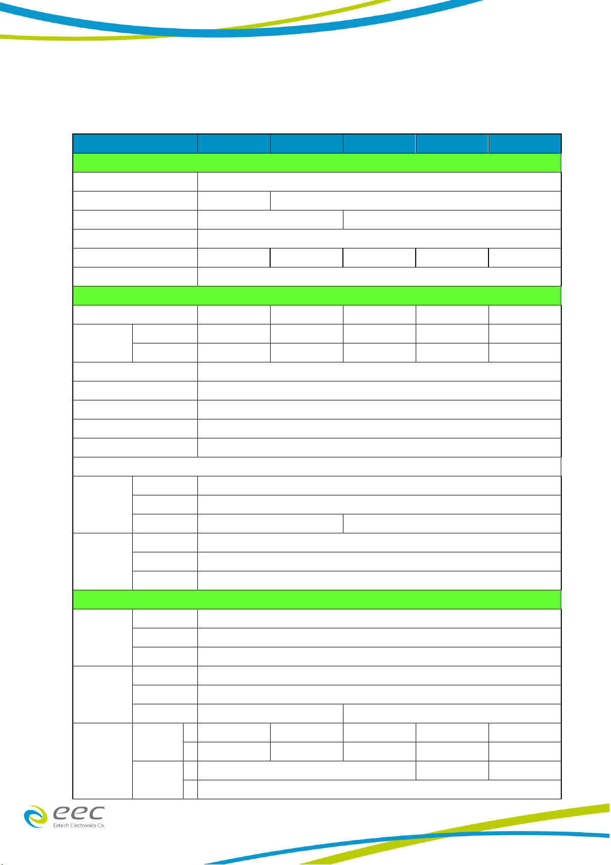
3.1 Specification
Model
6905S
6910S
6920S
6930S
6950S
INPUT
Phase
1
Terminal
Inlet
Terminal
Voltage
110 / 220Vac ± 10%
220Vac ± 10%
Frequency
47 –63Hz
Max. Current
10A / 5A
20A / 10A
20A
30A
50A
Power Factor
≧0.67
OUTPUT
Power rating
500VA
1000VA
2000VA
3000VA
5000VA(1)
Max. Current
(r.m.s)(2)
0-155V
4.6A
9.2A
18.4A
27.6A
46.0A
0-310V
2.3A
4.6A
9.2A
13.8A
23.0A
Phase
1Ø /2W
Total Harmonic Distortion (THD)
<0.3% at 110 / 220V & 50 / 60Hz (Resistive Load)
Crest Factor
≧3
Line Regulation
±0.1V
Load Regulation
± (0.5% of output + 0.5V) at Resistive Load
SETTING
Voltage
Range
0 - 310V, 155 / 310V Auto Range
Resolution
0.1V
Accuracy
±(1% of setting + 0.1% f.s)
±(1% of setting + 0.2% f.s)
Frequency
Range
40 - 450Hz Full Range Adjust
Resolution
0.1Hz at 40.0 - 99.9Hz , 1Hz at 100 - 450Hz
Accuracy
±0.03% of setting
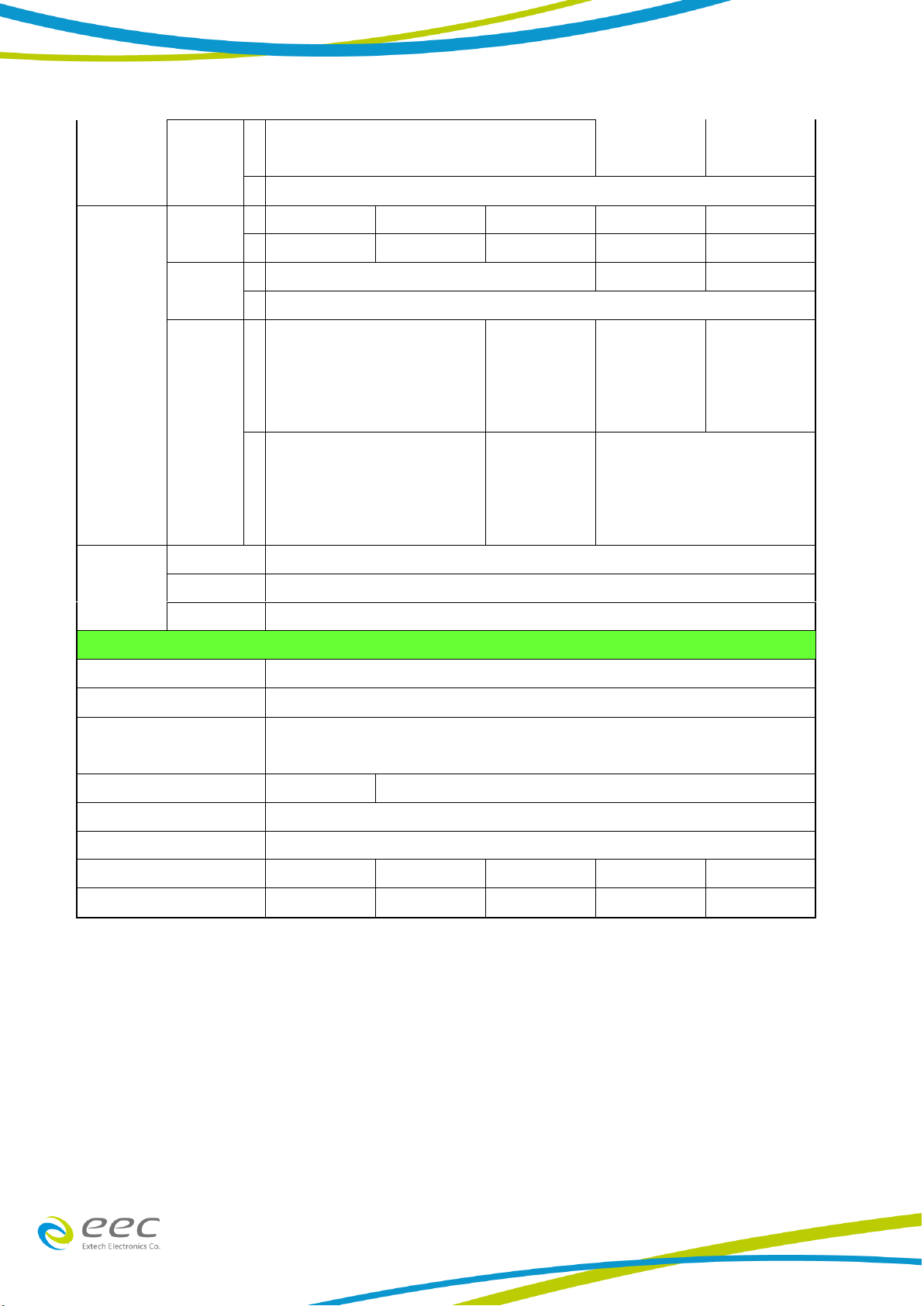
MEASUREMENT
Frequency
Range
0.0 - 450.0Hz
Resolution
0.1Hz
Accuracy
±0.1Hz
Voltage
Range
0.0 - 400.0V
Resolution
0.1V
Accuracy
±(1% of reading + 0.1% f.s)
±(1% of reading + 0.2% f.s)
Current
(r.m.s)
Range
L
0.005A - 0.600A
0.005A - 1.200A
0.005A - 2.400A
-
-
H
0.50A - 6.50A
1.00A - 13.00A
2.00A - 26.00A
0.05A - 39.00A
0.05A - 65.00A
Resolution
L
0.001A
-
-
H
0.01A
6
Accuracy
L
± (1% of reading + 0.005A)
at voltage > 5V
-
-
H
± (1% of reading +0.05A)
Power
Range
L
0.0W - 60W
0.0W - 120W
0.0W - 240W
-
-
H
50W - 650W
100W - 1300W
200W - 2600W
0W - 3900W
0W - 6500W
Resolution
L
0.1W
-
-
H
1W
Accuracy
L
± (2% of reading +1.5W)
at PF>=0.2 & voltage > 5V
± (2% of reading +
3W)
at PF>=0.2 &
voltage > 5V
-
-
H
± (2% of reading + 5W)
at PF>=0.2 & voltage > 5V
± (2% of reading
+10W)
at PF>=0.2 &
voltage > 5V
± (2% of reading + 5W)
at PF>=0.2 & voltage > 5V
Power Factor
Range
0 –1.000
Resolution
0.001
Accuracy
W / VA ,Calculated and displayed to three significant digits
GENERAL
Memory
3 memories
Display
Green LED
Over Current Fold Back
On/Off , Setting On when output current over setting Hi-A value it will fold back output voltage
to keep constant output current is setting Hi-A value, Response time < 1.4s
Efficiency
≧78%
≧80%
Protection
OCP, OVP, OPP, OTP, Short Circuit and Alarm
Operation Environment
0-40℃/ 20-80%RH
Dimension (W x H x D), mm
430 x 89 x 300
430 x 89 x 400
430 x 89 x 500
430 x 222 x 500
430 x 222 x 500
Weight
12.5Kg
18.2Kg
30Kg
57Kg
65Kg
Product specifications are subject to change without notice.
*1 When PF 0.8 output can work continuously
.
*2 At working voltage 110V / 220V
【Ordering Information】
OPT.629 Input Voltage 100V / 200V for 6905S & 6910S
OPT.630 Input Voltage 120V / 240V for 6905S & 6910S
OPT.631 Input Voltage 200V for 6920S & 6930S & 6950S
OPT.632 Input Voltage 240V for 6920S & 6930S & 6950S

7
6905S rated output current (PF=1)
6910S rated output current (PF=1)
6920S rated output current (PF=1)
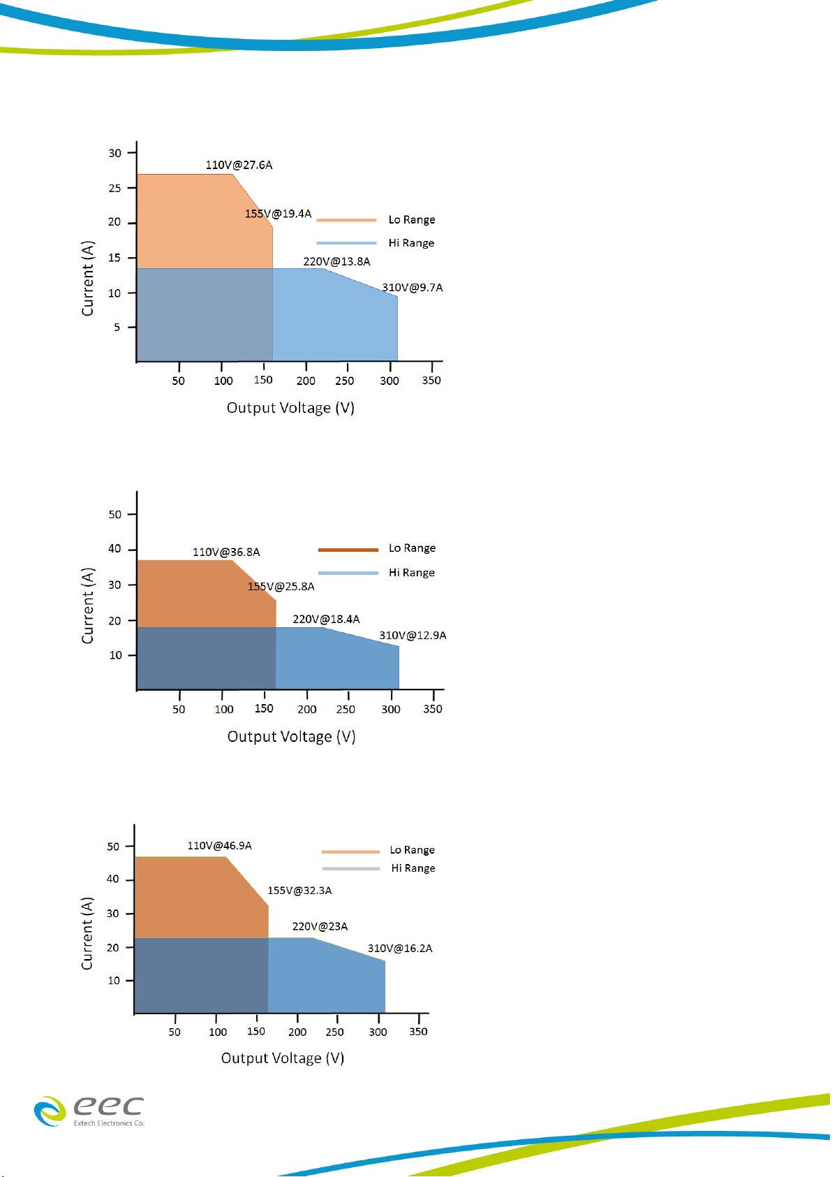
8
6930S rated output current (PF=1)
6950S rated output current (PF=1)
6950S rated output current (PF=0.8)
9
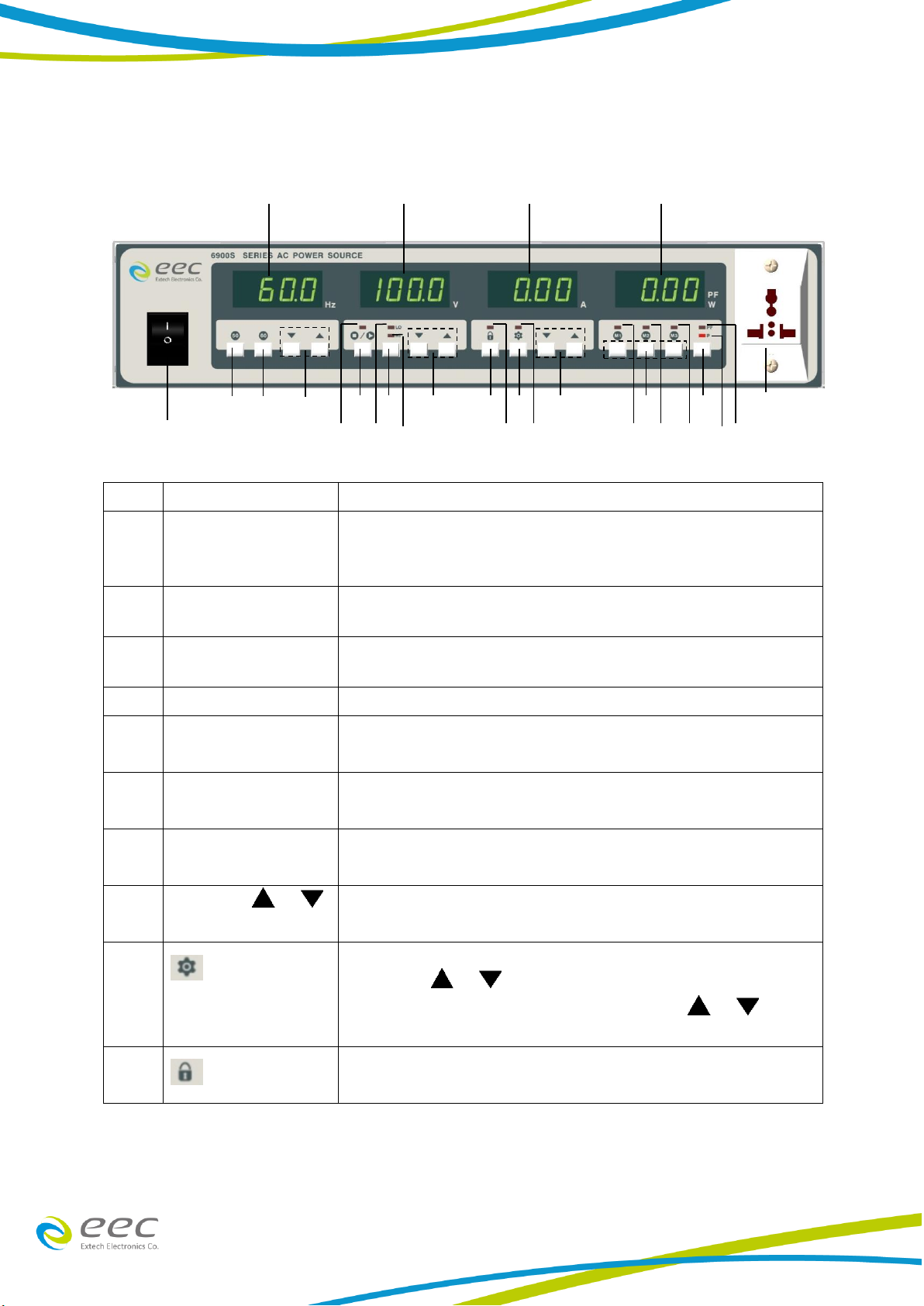
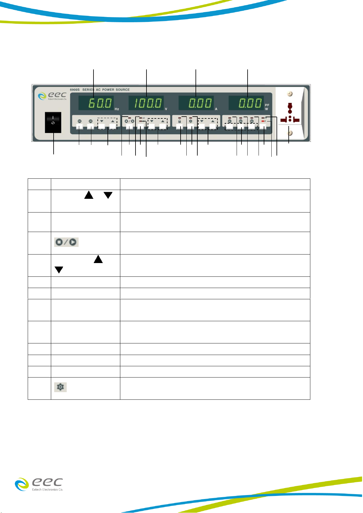
3.2 Front Panel Description
NO.
Item
Explain
1
FREQUENCY
It will display the output frequency. When the output is OFF,
it shows the frequency setting. Otherwise, it shows the
frequency of the output.
2
VOLTAGE
When the output is OFF it shows the output voltage setting.
Otherwise it shows the voltage of the output.
3
CURRENT
When the output is OFF it shows the output current setting.
Otherwise it shows the current of the output.
4
MULTI FUNCTION
Display the value of output wattage or power factor
5
UNIVERSAL AC
OUTPUT SOCKET
Trip Current (20A)
6
P / PF SELECT
BUTTON
Select the display of output wattage or power factor value.
7
M1, M2 AND M3
BUTTON
Store setting memories. [Press and hold for a second or
above].
8
CURRENT /
KEY
To increase or reduce the output current higher than the
display value. Or be a selection key for System conditions.
9
KEY
Enter or exit from the setting of system parameter. You can
utilize the / keys under VOLTAGE meter to select
the parameter that you need to set, and the / keys
under CURRENT meter to set parameters.
10
KEY
To disable all the keys on the front panel. It switches between
Lock and Unlock.
5
1
2
3
4
8
11
10
9
14
13
12
15
16
17
24
23
22
25
26
27
6
7
19
18
21
20
10
NO.
Item
Explain
11
VOLTAGE /
KEY
To increase the output voltage higher than the display value.
Or be a selection key for System items.
12
HI/LO KEY
High Range Voltage is 0 - 310V and Low Range Voltage is 0 -
155V.
13
KEY
To turn the output ON and OFF, and press RESET key as
abnormal operation occurs.
14
FREQUENCY /
KEY
To increase or reduce the output frequency to higher or lower
than the display value.
15
60 Hz KEY
Press to set the output frequency to 60 Hz.
16
50 Hz KEY
Press to set the output frequency to 50 Hz.
17
POWER FACTOR
INDICATOR
When the LED is ON, the display shows the output power
factor.
18
WATTMETER
INDICATOR
When this LED is ON, the display shows the output power.
19
M3 INDICATOR
When the LED is ON, the output is set according to M3.
20
M2 INDICATOR
When the LED is ON, the output is set according to M2.
21
M1 INDICATOR
When the LED is ON, the output is set according to M1.
22
INDICATOR
When the LED is ON, the SYSTEM default setting is activated.
5
1
2
3
4
8
11
10
9
14
13
12
15
16
17
24
23
22
25
26
27
6
7
19
18
21
20

11
NO.
Item
Explain
23
INDICATOR
When this LED is lit, all the keys are disabled.
24
HI INDICATOR
When the LED is lit, the output is set to high range.
25
LO INDICATOR
When the LED is lit, the output is set to low range.
26
INDICATOR
When the LED is lit, it is at normal operation, whereas when
the LED is blinking, it is at abnormal operation.
27
POWER SWITCH
Rocker style power switch with international ON ( ) and OFF
(0) markings.
5
1
2
3
4
8
11
10
9
14
13
12
15
16
17
24
23
22
25
26
27
6
7
19
18
21
20
12
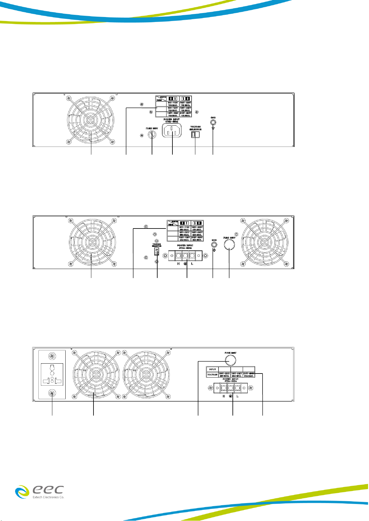
3.3 Rear Panel Description
6905S rear panel
6910S rear panel
6920S rear panel
1
1
2
2
3
3
4
5
5
6
8
8
1
2
6
7
8

13
6930S & 6950S rear panel
NO.
Item
Explain
1
THERMAL FAN
To cool the instrument.
When the temperature exceeds 60 °C, the fan will enter
the second speed.
2
FUSE RECEPTACLE
To change the fuse unplug the power (mains) cord and turn
the fuse cap counter clockwise to remove the fuse.
3
CHASSIS GROUND
This terminal should be connected to a good earth ground
before operation
4
INPUT POWER
RECEPTACLE
Standard IEC 320 connector for connection to a standard
NEMA style line power (mains) cord.
5
INPUT POWER SWITCH
Line voltage selection is set by the position of the switch.
In the left position, it is set for 110-volt operation, in the
right position it is set for 220-volt operation.
6
Input Terminal Power
Block
Provides input power to the instrument.
7
UNIVERSAL AC
OUTPUT SOCKET
Trip Current (20A)
8
Indicated the input
voltage range
Instrument input voltage indication
9
Input Circuit Breaker
Input power switch.
10
Output Terminal
Power Block
Provides output power to the DUT.
1
9
10
8
6

14
CHAPTER 4. MANUAL OPERATION
4.1 Manual Operation
1. Setting Of Output Voltage
High range voltage can be set between 0 - 310V while low range voltage is 0-155V under
AC mode. Press and hold the or key will firstly clear the decimal number of
setting to zero. Subsequently, every 0.3 seconds will change a step and thereafter a first
integer of setting number will vary and then to the second integer and third integer of the
voltage setting respectively. For the third integer, it takes 0.1 seconds only to vary every
step in order to speed up the scrolling.
Press and hold “︿”, decimal (clear to 0) → 1st Integer (0.3sec / step) → 2nd Integer (0.3sec / step)
→ 3rd Integer(0.1sec/step)
If the voltage is adjusted when the indicator is ON, the AC Power Source will
generate the output voltage accordingly. When the voltage display is blinking, the output
voltage remains the same as the previous set voltage. After 2 second the voltage display
will stop blinking and the new set voltage is accepted. Any invalid setting may not be
accepted.
2. Setting Of Output Frequency
For frequency setting in the range of 40-99.9 Hz, each change on the setting are
0.1Hz/step for normal setting and 1Hz/step for coarse setting. In 100-450 Hz range, each
change on the setting are 1Hz/step for normal setting and 10Hz/step for coarse setting. As
the 50 Hz or 60 Hz key is pressed, the desired frequency will be immediately updated. (The
same method applied like voltage setting to scroll the display).
3. Setting Of Voltage Range
If the desired voltage is lower than 155 V, press the HI / LO Key first. The LO LED is lighted
to indicate the AC source is in 0 - 155 Volt range and allow a higher range of current limit.
For the 0 - 310V of voltage range, the range of current limit drops to half as comparing the
current limit at the 0 - 155V range (Refer to the specification table). Setting of voltage
range may not influence the existing output voltage setting. Anyhow, changing the voltage
range during the indicator is ON will lead to the output voltage cutoff (about 20
ms) and this should be avoided if possible.
4. Setting Of Current
While the OUTPUT is not activated, pressing the or key will enter to the setting
mode of low-limit current. Press further or key to continue scrolling the display
in order to change the current limit. If the setting is hold for 2 seconds, it will return to a
standby mode from current setting mode. Meanwhile, at the standby mode, the output
capacity (Refer to the specification table) limits the output current or allows setting the
low limit current. The AC Power Source cuts off the output immediately when the actual
current has exceeded the limits and a HI-A error message is shown. Any invalid current
setting will not be accepted
This manual suits for next models
5
Table of contents
Other EEC AC Power Distribution manuals


