Efergy E2 User manual

EN
Wireless Electricity Monitor
Art. no 36-4500
Modell efergy e2

2
Points worth bearing in mind!
• Other wireless equipment operating on the same frequency band may
reduce the range of the product.
• The range of all wireless equipment is affected by obstacles between
the transmitter and the receiver (a concrete wall reduces the signal far
more than a plasterboard partition, for example).
If you are having problems with the operation of
the system, try the following solutions
• Switch off any other wireless equipment to check whether it could be
causing the problem.
• Move the wireless equipment and/or reduce the distance, and reduce the number
of obstacles (walls, furniture, etc.) between the transmitter and the receiver.

3
1. Contents
2. Introduction ....................................................................................................4
3. Safety .............................................................................................................5
4. Package contents ..........................................................................................6
5. Buttons and functions ....................................................................................7
5.1 Locating the power feed cable of your electricity meter (UK/Irland) .................7
5.2 Locating the power feed cable for your electricity meter (SE) (NO) (FI) .............9
6. Installation ....................................................................................................11
6.1 Fitting the sensors ........................................................................................11
6.2 Connect the sensor to the transmitter ..........................................................11
7. Linking the transmitter and display unit .........................................................12
8. Setting the time and date .............................................................................13
9. Single tariff setup ..........................................................................................14
10. Multiple tariff setup .......................................................................................16
11. Display information .......................................................................................18
12. Symbols on display ......................................................................................22
13. Toubleshooting/FAQ .....................................................................................23
14. Disposal .......................................................................................................25
15. Specifications ...............................................................................................25
16. Installing the provided software .....................................................................26

4
2. Introduction
Wireless Electricity Monitor
Art. no 36-4500 Model efergy e2
The metering and monitoring of energy is the basis for saving energy. You need this information
in order to know where and how you can save money.
Efergy is an electricity monitor which shows how much electrical energy is being consumed in your
home at the actual moment you read the display. The display can also inform the consumer how
much the consumed energy costs. You can walk around your home with the display unit and turn
electrical devices on and off to see the difference in power consumption directly on the display.
Please read the entire instruction manual before using the product and save it for future reference.
We reserve the right for any errors in text or images and any necessary changes made to technical
data. If you have any questions regarding technical problems please contact Customer Services.

5
3. Safety
IT IS VERY IMPORTANT THAT YOU TAKE INTO CONSIDERATION A FEW SIMPLE PRECAU-
TIONARY MEASURES BEFORE USING THIS PRODUCT.
Efergy electricity monitors are easy to install. Still, there are some essential safety rules that you
must be conscious of:
In the UK or Ireland the installation of the electricity monitor is easy, since the only thing that is
required is to connect a sensor to the incoming mains power cable. If you still feel unsure as to
how to fit the sensor, we recommend that you contact a qualified electrician.
In the Nordic countries a 3-phase system is used, which means that one must install all three
included sensors. The sensor clamps should be clamped over the incoming electrical cables in
or outside the distribution box. Contact a qualified electrician if you are in any doubt as to how
to fit the sensors.
Read and follow the important information contained in the following pages. Remember that the
electricity monitor’s sensors do not need to have direct electrical contact at the measuring point.
The sensors should sit around the cable.
If you find something unusual in or around the distribution box such as loose cables, bare cables,
burn marks, holes in the insulation material or any other damage, etc. you must immediately stop
work and contact your electric company or the person responsible for electrical installations.
Do not force or bend the cables in any way whilst fitting the sensors.
If you are uneasy or have any questions regarding the fitting of the electricity monitor’s sensors,
contact a qualified electrician immediately.
The sensors will not need to be removed at all during the normal useful operating life of the
electricity monitor. However, the transmitter and display unit require batteries that will need to be
changed occasionally.
6
Sensor Transmitter
Receiver
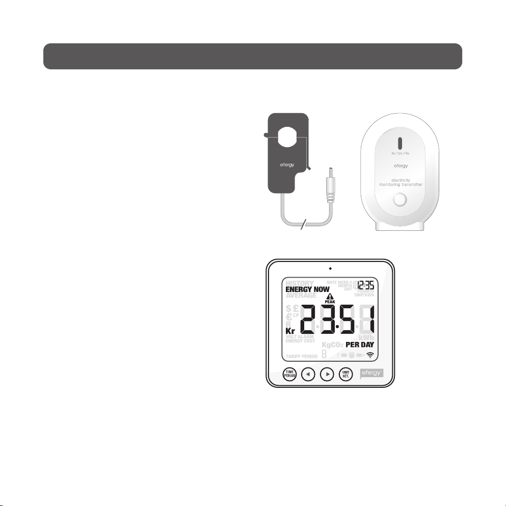
4. Package contents
3 x sensors (current transformers)
1 x transmitter
1 x display unit (receiver)
The package also contains:
1 x USB cable.
1 x booklet with advice on how
to save energy.
1 x CD-ROM software disc.
1 x instruction manual.
The sensors should be clamped onto the in-
coming mains power cables leading into the
distribution box. All electricity consumed in
the household enters through these cables.
The sensors measure the current which
passes through these cables. A reading of
the amount of current is then wirelessly sent
to the display unit via the transmitter. The
energy consumption is shown directly on
the display.

7
5. Buttons and functions
Display unit (receiver)
[time period] Save and finish.
[◄] Step left.
[►] Step right.
[unit/set] Confirm setting and advance.
[function] (on top) Function button for display setup.
[link] (on back) Link button for wireless linking to the transmitter.
[time set. alarm on/off] (on back) Setting the time.
Transmitter
Button for the wireless linking of the transmitter and receiver/display unit.
5.1 Locating the power feed cable of your electricity
meter/distribution box (UK/Irland)
The Efergy electricity monitor is installed by clamping the sensor around the mains power feeder
cable entering into your electricity meter.
Locating your electricity meter
Find your electricity meter and check which type you have. It is normally found on an outer wall,
in the garage, in the cellar or in a utility room. If you live in a flat, it may be located near the entry
door, in the stairway, or in the cellar. Make sure the cables exiting the bottom of the electricity
meter are accessible.
Modern offices and flats can have safety panels which protect the cables entering the electricity
meter. If this is your situation, we recommend that you contact a qualified electrician.
8
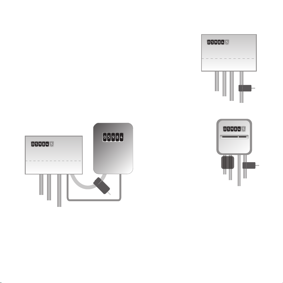
Finding the power supply feed cable
There are four cables at the bottom of the electricity meter. The cable
on the right (cable 4) is always the live feed cable (Active phase)
from the meter to the fuse box (see diagram 1).
Certain installations have cables 1 and 2 entirely or partially covered
in order to hinder modification or home installation of cables before
the meter (see diagram 2). Connect the sensor to cable 4 (on the
far right).
Meters with dual tariffs (see diagram 3) often have an extra cable
between cable 3 and 4. The extra cable has a smaller diameter than
the other cables and leads to another electricity meter close by.
Newer installations normally have two cables on the underside of the meter. One of the cables is
the earth cable and the other is the feed cable. The sensor should be clamped around the feed
cable (normally coloured brown).
If you have a 3-phase supply or if you have an Economy 7 meter you will need several sensors.
The extra sensors easily connect to the socket at the base of the transmitter. N.B. The electricity
monitor comes with 3 sensors.
1
2
34
1
2
3
4
1
2
3
Feed Wire
Feed Wire
Feed Wire
1
2
34
1
2
3
4
1
2
3
Feed Wire
Feed Wire
Feed Wire
Diagram 1
Diagram 2
Diagram 3
9
Safety
You should under no circumstances connect a sensor to a cable if any of the cables lead-
ing to the meter is damaged in any way. No cables need to be cut. Do not clip any cables.
Do not break any seals or such on the meter.
Contact your local electricity supplier if you are at all uncertain about connecting the
sensor to the correct cable. All work inside distribution boxes/consumer units must
be carried out by competent electricians.
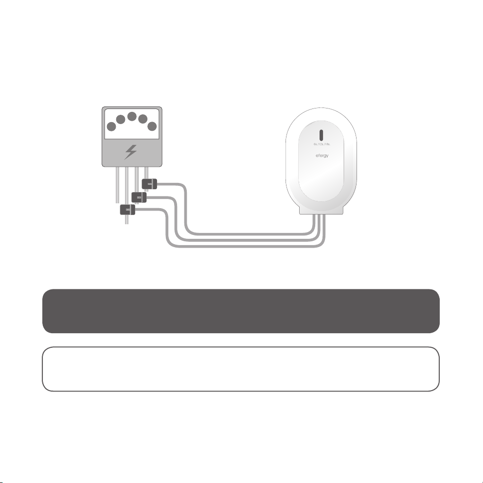
5.2 Locating the power feed cable of your
electricity meter (SE) (NO) (FI)
The Efergy electricity monitor is installed by clamping the sensor clips around the incoming mains
power cables leading to your electricity meter.
Locating your electricity meter/distribution box
Find out where your meter is located. It is normally found on an outer wall, in the garage, in the
cellar or in a utility room. If you live in a flat, it may be located near the entry door, in the stairway,
or in the cellar. Make sure the cables exiting the bottom of the electricity meter are accessible.
Modern homes and flats can have safety panels which protect the cables entering the meter.
These are often sealed. Under no circumstances should the seals be broken other than by
a competent electrician. Instead, we recommend that the sensors be fitted after the main
switch in your distribution box.
If you still feel unsure as to how to mount the sensor, we recommend that you contact a qualified
electrician.
10
Electricity meter
Sensor (3x)
Transmitter
Finding the power supply feed cable
In Sweden, Norway and Finland there are four feed cables entering the electricity meter: 3 live
phases (L1, L2, L3) and 1 neutral (N). The neutral cable is usually blue and the live cables are black
or brown. Cables L1 – L2 – L3 are live and it is these that the sensors should be attached to.
Safety
You should under no circumstances connect a sensor to a cable if any of the cables lead-
ing to the meter is damaged in any way. No cables need to be cut. Do not clip any cables.
Do not break any seals or such on the meter.
Contact your local electricity supplier if you are at all uncertain about fitting the sen-
sors to the correct cables. All work inside distribution boxes/consumer units must
be carried out by competent electricians.
Other manuals for E2
3
This manual suits for next models
1
Table of contents
Other Efergy Monitor manuals


