EFI Fiery Central Solo User manual

Fiery Central Solo for KM
Service Guide
A guide for service technicians
Replacement parts and specifications are subject to change. For a current
parts list, contact your authorized service/support center.

© 2019 Electronics For Imaging, Inc.
This documentation is protected by copyright, and all rights are reserved. No part of it may be reproduced or
transmitted in any form or by any means for any purpose without express prior written consent from Electronics For
Imaging, Inc. (“EFI”), except as expressly permitted herein. Information in this documentation is subject to change
without notice and does not represent a commitment on the part of EFI. The documentation is further covered by
Legal Notices distributed with this product. The documentation may be provided in conjunction with EFI Software
(“Software”) and any other EFI product described in the documentation. The Software is furnished under license and
may only be used or copied in accordance with the terms of the Software License Agreement, which can be found in
the “Legal Notices” distributed with this product.
23 December 2019 45204592
*45204592*

List of Figures . . . . . . . . . . . . . . . . . . . . . . . . . . . . . . . . . . . . . . . . . . . . . . . . . . . . . . . . . . . . . . . . . . . . . . . . . . . . . . . . . . . . . . . . . . . . . . . . 5
Introduction . . . . . . . . . . . . . . . . . . . . . . . . . . . . . . . . . . . . . . . . . . . . . . . . . . . . . . . . . . . . . . . . . . . . . . . . . . . . . . . . . . . . . . . . . . . . . . . . . . 6
About the FC Solo . . . . . . . . . . . . . . . . . . . . . . . . . . . . . . . . . . . . . . . . . . . . . . . . . . . . . . . . . . . . . . . . . . . . . . . . . . . . . . . . . . . . . . . . . . . . . . . . 6
About the illustrations in this document . . . . . . . . . . . . . . . . . . . . . . . . . . . . . . . . . . . . . . . . . . . . . . . . . . . . . . . . . . . . . . . . . . . . . . . . 6
Terminology and conventions . . . . . . . . . . . . . . . . . . . . . . . . . . . . . . . . . . . . . . . . . . . . . . . . . . . . . . . . . . . . . . . . . . . . . . . . . . . . . . . . . . 6
Precautions . . . . . . . . . . . . . . . . . . . . . . . . . . . . . . . . . . . . . . . . . . . . . . . . . . . . . . . . . . . . . . . . . . . . . . . . . . . . . . . . . . . . . . . . . . . . . . . . . . . . . . 7
Creating an ESD safe environment . . . . . . . . . . . . . . . . . . . . . . . . . . . . . . . . . . . . . . . . . . . . . . . . . . . . . . . . . . . . . . . . . . . . . . . . . . . . . . 9
Tools you will need . . . . . . . . . . . . . . . . . . . . . . . . . . . . . . . . . . . . . . . . . . . . . . . . . . . . . . . . . . . . . . . . . . . . . . . . . . . . . . . . . . . . . . . . . . . . . . . 9
Using the FC Solo . . . . . . . . . . . . . . . . . . . . . . . . . . . . . . . . . . . . . . . . . . . . . . . . . . . . . . . . . . . . . . . . . . . . . . . . . . . . . . . . . . . . . . . . . . 12
Using the FC Solo control panel . . . . . . . . . . . . . . . . . . . . . . . . . . . . . . . . . . . . . . . . . . . . . . . . . . . . . . . . . . . . . . . . . . . . . . . . . . . . . . . . . . 12
Buttons. . . . . . . . . . . . . . . . . . . . . . . . . . . . . . . . . . . . . . . . . . . . . . . . . . . . . . . . . . . . . . . . . . . . . . . . . . . . . . . . . . . . . . . . . . . . . . . . . . . . . . . 13
Network Status LEDs . . . . . . . . . . . . . . . . . . . . . . . . . . . . . . . . . . . . . . . . . . . . . . . . . . . . . . . . . . . . . . . . . . . . . . . . . . . . . . . . . . . . . . . . . . 13
Starting, shutting down, restarting, and rebooting. . . . . . . . . . . . . . . . . . . . . . . . . . . . . . . . . . . . . . . . . . . . . . . . . . . . . . . . . . . . . . . . 13
Service Procedures. . . . . . . . . . . . . . . . . . . . . . . . . . . . . . . . . . . . . . . . . . . . . . . . . . . . . . . . . . . . . . . . . . . . . . . . . . . . . . . . . . . . . . . . . 16
Overview. . . . . . . . . . . . . . . . . . . . . . . . . . . . . . . . . . . . . . . . . . . . . . . . . . . . . . . . . . . . . . . . . . . . . . . . . . . . . . . . . . . . . . . . . . . . . . . . . . . . . . . . 16
FC Solo overview diagrams. . . . . . . . . . . . . . . . . . . . . . . . . . . . . . . . . . . . . . . . . . . . . . . . . . . . . . . . . . . . . . . . . . . . . . . . . . . . . . . . . . . . 17
Accessing internal components . . . . . . . . . . . . . . . . . . . . . . . . . . . . . . . . . . . . . . . . . . . . . . . . . . . . . . . . . . . . . . . . . . . . . . . . . . . . . . . . . . 21
Shutting down the system . . . . . . . . . . . . . . . . . . . . . . . . . . . . . . . . . . . . . . . . . . . . . . . . . . . . . . . . . . . . . . . . . . . . . . . . . . . . . . . . . . . . 22
Opening the FC Solo . . . . . . . . . . . . . . . . . . . . . . . . . . . . . . . . . . . . . . . . . . . . . . . . . . . . . . . . . . . . . . . . . . . . . . . . . . . . . . . . . . . . . . . . . . 22
Removing and replacing FC Solo components. . . . . . . . . . . . . . . . . . . . . . . . . . . . . . . . . . . . . . . . . . . . . . . . . . . . . . . . . . . . . . . . . . . . 25
User Interface Board . . . . . . . . . . . . . . . . . . . . . . . . . . . . . . . . . . . . . . . . . . . . . . . . . . . . . . . . . . . . . . . . . . . . . . . . . . . . . . . . . . . . . . . . . . 26
Motherboard . . . . . . . . . . . . . . . . . . . . . . . . . . . . . . . . . . . . . . . . . . . . . . . . . . . . . . . . . . . . . . . . . . . . . . . . . . . . . . . . . . . . . . . . . . . . . . . . . 29
Replacing parts on the motherboard . . . . . . . . . . . . . . . . . . . . . . . . . . . . . . . . . . . . . . . . . . . . . . . . . . . . . . . . . . . . . . . . . . . . . . . . . . 35
DIMM. . . . . . . . . . . . . . . . . . . . . . . . . . . . . . . . . . . . . . . . . . . . . . . . . . . . . . . . . . . . . . . . . . . . . . . . . . . . . . . . . . . . . . . . . . . . . . . . . . . . . . . . . 36
CPU and CPU cooling assembly. . . . . . . . . . . . . . . . . . . . . . . . . . . . . . . . . . . . . . . . . . . . . . . . . . . . . . . . . . . . . . . . . . . . . . . . . . . . . . . . 37
Chassis fan. . . . . . . . . . . . . . . . . . . . . . . . . . . . . . . . . . . . . . . . . . . . . . . . . . . . . . . . . . . . . . . . . . . . . . . . . . . . . . . . . . . . . . . . . . . . . . . . . . . . 41
Power supply . . . . . . . . . . . . . . . . . . . . . . . . . . . . . . . . . . . . . . . . . . . . . . . . . . . . . . . . . . . . . . . . . . . . . . . . . . . . . . . . . . . . . . . . . . . . . . . . . 42
Hard disk drive. . . . . . . . . . . . . . . . . . . . . . . . . . . . . . . . . . . . . . . . . . . . . . . . . . . . . . . . . . . . . . . . . . . . . . . . . . . . . . . . . . . . . . . . . . . . . . . . 45
DVD drive. . . . . . . . . . . . . . . . . . . . . . . . . . . . . . . . . . . . . . . . . . . . . . . . . . . . . . . . . . . . . . . . . . . . . . . . . . . . . . . . . . . . . . . . . . . . . . . . . . . . . 48
Restoring and verifying functionality after service . . . . . . . . . . . . . . . . . . . . . . . . . . . . . . . . . . . . . . . . . . . . . . . . . . . . . . . . . . . . . . . . 50
Contents

4Service Guide: Fiery Central Solo for KM
Contents
Installing FC Solo Software. . . . . . . . . . . . . . . . . . . . . . . . . . . . . . . . . . . . . . . . . . . . . . . . . . . . . . . . . . . . . . . . . . . . . . . . . . . . . . . 51
Server software installation . . . . . . . . . . . . . . . . . . . . . . . . . . . . . . . . . . . . . . . . . . . . . . . . . . . . . . . . . . . . . . . . . . . . . . . . . . . . . . . . . . . . . . 51
Installing the system software . . . . . . . . . . . . . . . . . . . . . . . . . . . . . . . . . . . . . . . . . . . . . . . . . . . . . . . . . . . . . . . . . . . . . . . . . . . . . . . . . 51
Installing the hardware security key . . . . . . . . . . . . . . . . . . . . . . . . . . . . . . . . . . . . . . . . . . . . . . . . . . . . . . . . . . . . . . . . . . . . . . . . . . . . . . 52
Fiery Central License Manager . . . . . . . . . . . . . . . . . . . . . . . . . . . . . . . . . . . . . . . . . . . . . . . . . . . . . . . . . . . . . . . . . . . . . . . . . . . . . . . . . . . 53
Configuring FC Solo . . . . . . . . . . . . . . . . . . . . . . . . . . . . . . . . . . . . . . . . . . . . . . . . . . . . . . . . . . . . . . . . . . . . . . . . . . . . . . . . . . . . . . . . . . . . . 54
Fiery Central Configure. . . . . . . . . . . . . . . . . . . . . . . . . . . . . . . . . . . . . . . . . . . . . . . . . . . . . . . . . . . . . . . . . . . . . . . . . . . . . . . . . . . . . . . . 55
Troubleshooting. . . . . . . . . . . . . . . . . . . . . . . . . . . . . . . . . . . . . . . . . . . . . . . . . . . . . . . . . . . . . . . . . . . . . . . . . . . . . . . . . . . . . . . . . . . . 57
Troubleshooting process. . . . . . . . . . . . . . . . . . . . . . . . . . . . . . . . . . . . . . . . . . . . . . . . . . . . . . . . . . . . . . . . . . . . . . . . . . . . . . . . . . . . . . . . . 57
Preliminary on-site checkout . . . . . . . . . . . . . . . . . . . . . . . . . . . . . . . . . . . . . . . . . . . . . . . . . . . . . . . . . . . . . . . . . . . . . . . . . . . . . . . . . . . . . 57
Checking external connections . . . . . . . . . . . . . . . . . . . . . . . . . . . . . . . . . . . . . . . . . . . . . . . . . . . . . . . . . . . . . . . . . . . . . . . . . . . . . . . . 58
Checking internal components . . . . . . . . . . . . . . . . . . . . . . . . . . . . . . . . . . . . . . . . . . . . . . . . . . . . . . . . . . . . . . . . . . . . . . . . . . . . . . . . 58
Inspecting the system. . . . . . . . . . . . . . . . . . . . . . . . . . . . . . . . . . . . . . . . . . . . . . . . . . . . . . . . . . . . . . . . . . . . . . . . . . . . . . . . . . . . . . . . . 59
Normal startup sequence . . . . . . . . . . . . . . . . . . . . . . . . . . . . . . . . . . . . . . . . . . . . . . . . . . . . . . . . . . . . . . . . . . . . . . . . . . . . . . . . . . . . . 63
Error messages and conditions. . . . . . . . . . . . . . . . . . . . . . . . . . . . . . . . . . . . . . . . . . . . . . . . . . . . . . . . . . . . . . . . . . . . . . . . . . . . . . . . . . . 63
Specifications . . . . . . . . . . . . . . . . . . . . . . . . . . . . . . . . . . . . . . . . . . . . . . . . . . . . . . . . . . . . . . . . . . . . . . . . . . . . . . . . . . . . . . . . . . . . . . . 69
Hardware features . . . . . . . . . . . . . . . . . . . . . . . . . . . . . . . . . . . . . . . . . . . . . . . . . . . . . . . . . . . . . . . . . . . . . . . . . . . . . . . . . . . . . . . . . . . . . . . 69
Physical specifications . . . . . . . . . . . . . . . . . . . . . . . . . . . . . . . . . . . . . . . . . . . . . . . . . . . . . . . . . . . . . . . . . . . . . . . . . . . . . . . . . . . . . . . . . . . 69
Safety and emissions compliance . . . . . . . . . . . . . . . . . . . . . . . . . . . . . . . . . . . . . . . . . . . . . . . . . . . . . . . . . . . . . . . . . . . . . . . . . . . . . . . . 69
Index . . . . . . . . . . . . . . . . . . . . . . . . . . . . . . . . . . . . . . . . . . . . . . . . . . . . . . . . . . . . . . . . . . . . . . . . . . . . . . . . . . . . . . . . . . . . . . . . . . . . . . . . . . 71

Figure 1: FC Solo control panel . . . . . . . . . . . . . . . . . . . . . . . . . . . . . . . . . . . . . . . . . . . . . . . . . . . . . . . . . . . . . . . . . . . . . . . . . . . . . . . . 12
Figure 2: Front and connector panels . . . . . . . . . . . . . . . . . . . . . . . . . . . . . . . . . . . . . . . . . . . . . . . . . . . . . . . . . . . . . . . . . . . . . . . . . . 17
Figure 3: Internal side view . . . . . . . . . . . . . . . . . . . . . . . . . . . . . . . . . . . . . . . . . . . . . . . . . . . . . . . . . . . . . . . . . . . . . . . . . . . . . . . . . . . . 18
Figure 4: Exploded view of FC Solo components . . . . . . . . . . . . . . . . . . . . . . . . . . . . . . . . . . . . . . . . . . . . . . . . . . . . . . . . . . . . . . . 19
Figure 5: Data cable connections in the FC Solo . . . . . . . . . . . . . . . . . . . . . . . . . . . . . . . . . . . . . . . . . . . . . . . . . . . . . . . . . . . . . . . . 20
Figure 6: Power cable connections in the FC Solo. . . . . . . . . . . . . . . . . . . . . . . . . . . . . . . . . . . . . . . . . . . . . . . . . . . . . . . . . . . . . . . 21
Figure 7: Removing/replacing the side panel . . . . . . . . . . . . . . . . . . . . . . . . . . . . . . . . . . . . . . . . . . . . . . . . . . . . . . . . . . . . . . . . . . . 23
Figure 8: Removing/replacing the top panel . . . . . . . . . . . . . . . . . . . . . . . . . . . . . . . . . . . . . . . . . . . . . . . . . . . . . . . . . . . . . . . . . . . 24
Figure 9: Removing/replacing the front panel . . . . . . . . . . . . . . . . . . . . . . . . . . . . . . . . . . . . . . . . . . . . . . . . . . . . . . . . . . . . . . . . . . 25
Figure 10: Diagram of the User Interface Board (front and back) . . . . . . . . . . . . . . . . . . . . . . . . . . . . . . . . . . . . . . . . . . . . . . . . 27
Figure 11: Removing/replacing the User Interface Board . . . . . . . . . . . . . . . . . . . . . . . . . . . . . . . . . . . . . . . . . . . . . . . . . . . . . . . 28
Figure 12: Motherboard battery . . . . . . . . . . . . . . . . . . . . . . . . . . . . . . . . . . . . . . . . . . . . . . . . . . . . . . . . . . . . . . . . . . . . . . . . . . . . . . . 30
Figure 13: Cable connections for power button . . . . . . . . . . . . . . . . . . . . . . . . . . . . . . . . . . . . . . . . . . . . . . . . . . . . . . . . . . . . . . . . 31
Figure 14: Diagram of the FC Solo motherboard. . . . . . . . . . . . . . . . . . . . . . . . . . . . . . . . . . . . . . . . . . . . . . . . . . . . . . . . . . . . . . . . 32
Figure 15: Removing the motherboard from the chassis . . . . . . . . . . . . . . . . . . . . . . . . . . . . . . . . . . . . . . . . . . . . . . . . . . . . . . . . 34
Figure 16: Removing or replacing a DIMM . . . . . . . . . . . . . . . . . . . . . . . . . . . . . . . . . . . . . . . . . . . . . . . . . . . . . . . . . . . . . . . . . . . . . 36
Figure 17: CPU cooling assembly . . . . . . . . . . . . . . . . . . . . . . . . . . . . . . . . . . . . . . . . . . . . . . . . . . . . . . . . . . . . . . . . . . . . . . . . . . . . . . 37
Figure 18: Removing the CPU cooling assembly. . . . . . . . . . . . . . . . . . . . . . . . . . . . . . . . . . . . . . . . . . . . . . . . . . . . . . . . . . . . . . . . 38
Figure 19: Removing/replacing the CPU . . . . . . . . . . . . . . . . . . . . . . . . . . . . . . . . . . . . . . . . . . . . . . . . . . . . . . . . . . . . . . . . . . . . . . . 39
Figure 20: Locating the flat corner of the CPU socket . . . . . . . . . . . . . . . . . . . . . . . . . . . . . . . . . . . . . . . . . . . . . . . . . . . . . . . . . . . 40
Figure 21: Removing/replacing the chassis fan . . . . . . . . . . . . . . . . . . . . . . . . . . . . . . . . . . . . . . . . . . . . . . . . . . . . . . . . . . . . . . . . . 42
Figure 22: Removing/replacing the power supply . . . . . . . . . . . . . . . . . . . . . . . . . . . . . . . . . . . . . . . . . . . . . . . . . . . . . . . . . . . . . . 44
Figure 23: Removing/replacing the hard disk drive bracket . . . . . . . . . . . . . . . . . . . . . . . . . . . . . . . . . . . . . . . . . . . . . . . . . . . . . 46
Figure 24: Removing/replacing the hard disk drive from the hard disk drive bracket. . . . . . . . . . . . . . . . . . . . . . . . . . . . .47
Figure 25: Removing/replacing the DVD drive bracket. . . . . . . . . . . . . . . . . . . . . . . . . . . . . . . . . . . . . . . . . . . . . . . . . . . . . . . . . . 49
Figure 26: Removing/replacing the DVD drive. . . . . . . . . . . . . . . . . . . . . . . . . . . . . . . . . . . . . . . . . . . . . . . . . . . . . . . . . . . . . . . . . . 49
List of Figures

Introduction
The Installation and Service Guide is intended for authorized Fiery Central Solo for KM service technicians. If you are
not an authorized service technician, do not attempt to service the Fiery Central Solo for KM. Electronics For Imaging
does not warrant the performance of the Fiery Central Solo for KM if it is serviced by non-authorized personnel.
Note: The term “FC Solo” is used throughout this document to refer to the Fiery Central Solo for KM.
About the FC Solo
FC Solo is a server computer that runs Fiery Central software. Fiery Central software is a modular, PDF-based
production workflow tool that provides efficient network printing to high-volume print environments.
For more information on Fiery Central software, refer to the documentation that is included in the software kit.
About the illustrations in this document
Illustrations reflect the current shipping version of the FC Solo at the time of publication. Components shown in these
illustrations are subject to change. To receive information about any FC Solo components that do not match the
illustrations in this document, contact your authorized service/support center.
Terminology and conventions
The following sections explain the terminology and conventions used throughout this document.
FC Solo components
•The terms “replace” and “replacing” are used throughout this document to refer to the reinstallation of existing
components. Install new components only when necessary.
Note: Replacement parts and specifications are subject to change. When ordering replacement parts, refer to the
current parts list maintained by your authorized service/support center. Install the correct parts as directed by
your service/support center.
•The term “control panel” refers to the area on the front of the FC Solo including the green/red activity light, the
display window (LCD—liquid crystal display), and the buttons to the left and right of the display window.
•The term “LCD” refers to the display window of the FC Solo control panel.
•The term “monitor” refers to the FC Solo optional flat panel monitor.
•The term “DVD drive” (Digital Versatile Disk drive) refers to the FC Solo DVD drive.
For other terms used to identify components of the FC Solo, see the reference key in Figure 4 on page 19.
7Service Guide: Fiery Central Solo for KM
Introduction
Document conventions
Note: The Note: format highlights important messages and additional information.
The IMPORTANT icon indicates operational requirements and restrictions. To operate the FC Solo correctly and
avoid damage to the FC Solo or other property, always pay attention to IMPORTANT icons and messages.
Precautions
Always observe the following general precautions when installing and servicing the FC Solo:
Avertissement: Ne jamais soulever le serveur d'impression par sa partie supérieure : celle-ci ne peut pas supporter le
poids du système.
Avvertenza: Il server di stampa non deve essere mai sollevato afferrandolo dal pannello superiore, in quanto
quest'ultimo non può sostenere il peso dell'intero sistema.
Warnung: Heben Sie den Druckserver nicht an der oberen Gehäuseabdeckung an. Die obere Gehäuseabdeckung ist
nicht dafür ausgelegt, das Gesamtgewicht des Systems zu tragen.
Advertencia: No levante nunca el servidor de impresión agarrándolo por el panel superior. El panel superior no
soporta el peso del sistema.
Aviso: Nunca erga o servidor de impressão pelo painel superior. O painel superior não suporta o peso do sistema.
Waarschuwing: Til de afdrukserver nooit op door het bovenpaneel vast te nemen. Het bovenpaneel kan het gewicht
van het systeem niet dragen.
•Avoid pressing the surface of the LCD.
Applying excessive pressure to the LCD causes it to change color.
DANGER The DANGER icon indicates a warning concerning operations which, if not performed correctly, may
lead to death or injury. To use the FC Solo safely, always pay attention to WARNING icons and
messages.
WARNING The WARNING icon indicates a caution concerning operations which, if not performed correctly, may
lead to injury. To use the FC Solo safely, always pay attention to CAUTION icons and messages.
CAUTION The CAUTION icon indicates operational requirements and restrictions. To operate the FC Solo
correctly and avoid damage to the FC Solo or other property, always pay attention to IMPORTANT
icons and messages.
DANGER Never lift the print server by grasping the top panel. The top panel does not support the weight of the
system.
•Use a soft cloth moistened with Lens and Mirror Cleaner to clean the surface of the FC Solo display window.
Other solvents, such as water, may damage the polarizer on the display window.
•When connecting or disconnecting the power cord:
•Only use the power cord that shipped with the FC Solo or an appropriate replacement power cord available from
an authorized provider.
•Always disconnect the power cord from the FC Solo connector panel before opening the unit and servicing
internal components.
•Do not pull on the power cord when unplugging the FC Solo. Pull the plug instead.
•Do not place objects on the power cord. Place the power cord away from foot traffic.
•Do not tamper with or disable the power cord grounding plug.
•Do not use a 3-prong adapter in a 2-hole, ungrounded power outlet.
•Do not use an extension cord.
•Do not plug the FC Solo into a circuit with heating or refrigeration equipment (including water dispensers).
•Do not plug the FC Solo into a switchable power outlet. This can result in the FC Solo being turned off
accidentally.
•Do not attempt to open the power supply, DVD drive, or hard disk drive.
•Handle the FC Solo LCD window with care.
If the FC Solo LCD window breaks and the liquid crystal inside leaks out, avoid contact with it. If you come in
contact with the liquid crystal, wash it off your skin with soap and water immediately.
•Use care when handling parts of the FC Solo, as some edges on the unit may be sharp.
•Do not install third-party applications onto the FC Solo. Third-party applications are not supported and can cause
system problems. Although virus scans are permitted on the FC Solo, virus-protection software should not be
loaded in memory-resident mode.
•Do not change the Windows operating system preference settings.
Depending on the changes made, the FC Solo may become unstable or even unusable. If this occurs, it is
recommended that you reinstall the FC Solo System Software, which reliably restores the Windows operating
system to its factory defaults.
DANGER The FC Solo contains hazardous moving parts. When servicing the FC Solo, keep away from moving
fan blades.

9Service Guide: Fiery Central Solo for KM
Introduction
•Never alter an existing network without permission.
The FC Solo will probably be connected to an existing Local Area Network (LAN) based on Ethernet hardware.
The network is the link between the customer’s computer, existing laser printers, and other prepress equipment.
Never disturb the LAN by breaking or making a network connection, altering termination, installing or removing
networking hardware or software, or shutting down networked devices without the knowledge and explicit
permission of the system or network administrator or the shop supervisor.
Creating an ESD safe environment
•Follow standard ESD (electrostatic discharge) precautions while working on the internal components of the FC
Solo.
Static is always a concern when servicing electronic devices. It is highly unlikely that the area around the FC Solo is
static-free. Carpeting, leather-soled shoes, synthetic clothing fibers, silks, and plastics may generate a static charge
of more than 10,000 volts. Static discharge is capable of destroying the circuits etched in silicon microchips, or
dramatically shortening their life span. By observing standard precautions, you may avoid extra service calls and
save the cost of a new board.
When possible, work on a ground-connected antistatic mat. Wear an antistatic grounding strap, grounded at the
same place as the antistatic mat. If that is not possible, do the following:
•Attach a grounding strap to your wrist. Attach the other end to a good ground.
•When you unpack the FC Solo from the carton for the first time, touch a metal area of the FC Solo to discharge the
static on your body.
•Before you remove any of the FC Solo panels and handle internal components, touch a metal part of the FC Solo.
•Leave new electronic components inside their antistatic bags until you are ready to install them. When you remove
components from an antistatic bag, place them on a grounded antistatic surface, component-side up.
•When you remove an electronic component, place it in an antistatic bag immediately. Do not walk across a carpet
or vinyl floor while carrying an unprotected board.
•During service to the motherboard, avoid using excessive force and always place the motherboard on a grounded,
nonmetallic, static-free surface. Never allow any metal to touch the solder contacts on the underside of the
motherboard, especially beneath the battery socket. Improper handling can short-circuit and permanently damage
the motherboard.
•Handle printed circuit boards by their opposing edges only and avoid touching the contacts on the edge of the
board.
Tools you will need
To service the FC Solo, the following tools and parts are required:
•ESD wrist grounding strap and antistatic mat
•Flathead screwdriver

•#0, #1, and #2 Phillips-head screwdrivers
•FC Solo documentation, including the customer media pack and any related service bulletins
Note: The FC Solo Service Guide is not intended for customer use. Do not leave the Service Guide at the customer site
after servicing the FC Solo.
CAUTION Avoid touching magnetic tools to storage media such as hard disk drives. Contact between magnetic
tools and magnetic storage media may result in data corruption.

11Service Guide: Fiery Central Solo for KM
Introduction
Using the FC Solo
This chapter includes the following information:
•Using the FC Solo control panel
•Checking Network status LEDs
•Shutting down and restarting the FC Solo
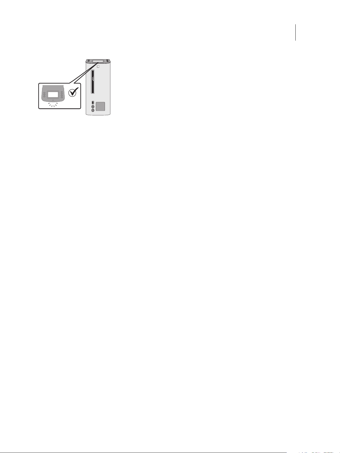
Using the FC Solo control panel
During normal FC Solo operation, the control panel displays a static logo screen and the buttons are not functional.
However, during installation of FC Solo server software, the control panel displays screens that allow you to proceed
through the steps of the installation.
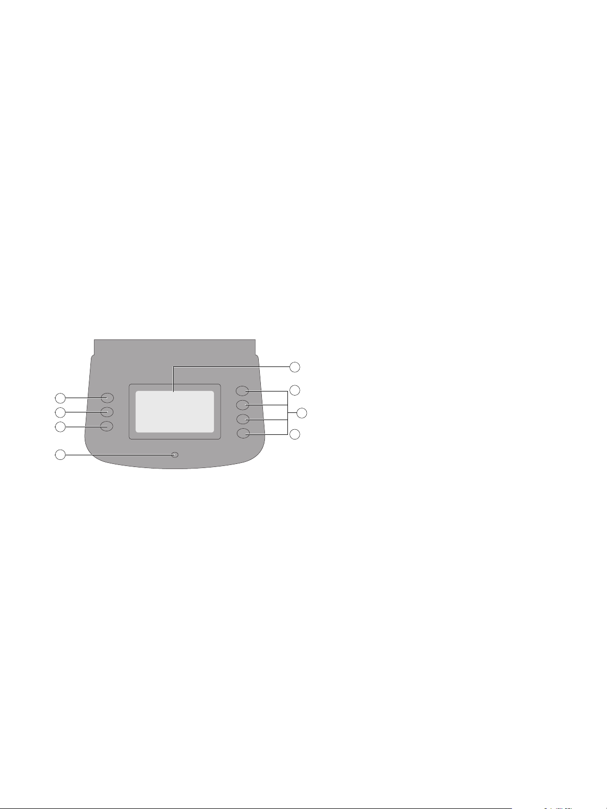
Figure 1: FC Solo control panel
1 Up button 5 Display window
2 Menu button 6 Line selection buttons
3 Down button 7 First
4 Activity light 8 Fourth
1
2
3
4
5
6
7
8
13Service Guide: Fiery Central Solo for KM
Using the FC Solo
Buttons
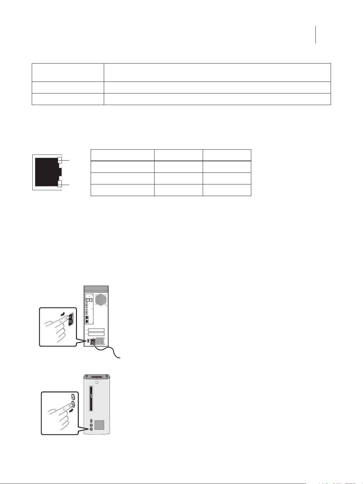
Network Status LEDs
Two LEDs next to the Ethernet network port indicate the network speed. When data transfer occurs between the FC
Solo and the network, the appropriate LED(s) blink to indicate network activity.
Starting, shutting down, restarting, and rebooting
The customer will generally leave the FC Solo on all the time. Power off the FC Solo when you need to service it and
before you remove or attach any cables to it.
To start the FC Solo
1Make sure that the power cable is attached and that the power switch is in the ON position.
2Press the power button on the front panel.
Line selection buttons Use the four line selection buttons on the right side of the control panel to select the command
displayed on the corresponding line of the LCD display.
Up and Down buttons Use these buttons to scroll to different screens in multi-screen lists or prompts.
Menu button This button is not functional.
Network link speed LED 1 LED 2
10 Megabits/second Off Green
100 Megabits/second Green Green
1000 Megabits/second Amber Green
LED 2
LED 1
Ethernet network port
(Upper RJ-45)
14Service Guide: Fiery Central Solo for KM
Using the FC Solo
3Check the Activity light on the control panel.
The power supply automatically senses the correct voltage. Allow startup to proceed without interruption.
4At the Admin login, enter the password, and then press Enter. Wait for Command WorkStation to start and for
Fiery Central Bar to indicate that the FC Solo is Idle.
Fiery.1. is the default password and is case-sensitive. However, the network administrator may have changed the
password.
During installation, a localhost connection to Command WorkStation is created, so when you start the FC Solo,
Command WorkStation starts also.
To shut down or reboot the FC Solo
Note: A monitor, keyboard, and mouse are required to shut down or reboot the FC Solo. Use the reset button on the
front of the FC Solo only if the system is unresponsive to keyboard or mouse actions.
1On the monitor, click the Windows Start button.
2Do one of the following:
•To shut down the FC Solo, click “Shut down.”
•To reboot the FC Solo operating system, click the triangle next to “Shut down” and then click Restart.
To restart the FC Solo server
•On the monitor, right-click Fiery Central Bar and click Restart Fiery Central.

15Service Guide: Fiery Central Solo for KM
Using the FC Solo

Service Procedures
Generally, the FC Solo requires no regular service or maintenance. Use the procedures in this chapter to inspect,
remove, reseat, and replace major hardware components if needed.
Overview
This chapter includes information about servicing the following components:
•Boards and cables
•Motherboard components (DIMMs, CPU, battery, CMOS, and jumpers)
•Fan
•Power supply
•Hard disk drive
Replacement parts are available from your authorized service representative. The terms “replace” and “replacing” are
used throughout this document to mean the reinstallation of existing components. Install new components only when
necessary. If you determine that a component you have removed is not faulty, make sure to reinstall it.
Replacement parts and specifications are subject to change. When ordering replacement parts, refer to the current
parts list maintained by your authorized service/support center. Install the correct parts as directed by your service/
support center.
The tools required to service the FC Solo are listed on page 9.
WARNING When performing the service procedures described in this chapter, follow the precautions listed on
page 7.
17Service Guide: Fiery Central Solo for KM
Service Procedures
FC Solo overview diagrams
The following figures provide an overview of FC Solo components.
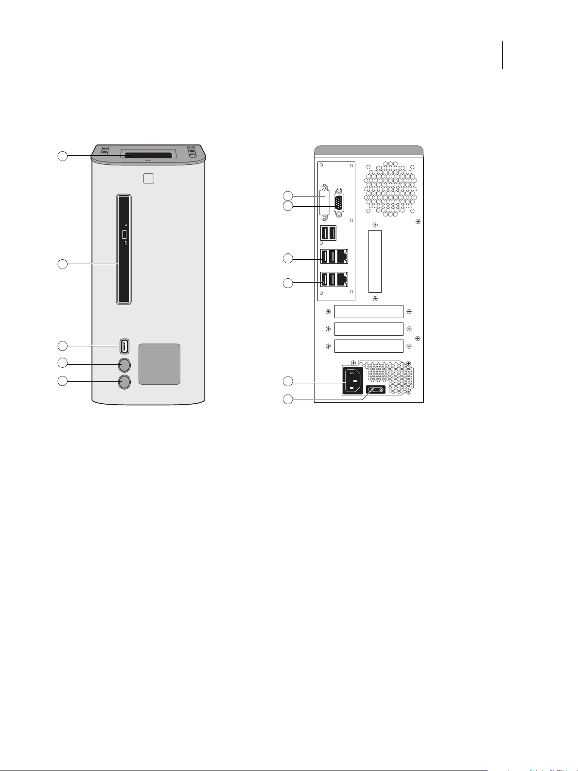
Figure 2: Front and connector panels
Front panel Connector panel
1 control panel 6 DVI port (covered)
2 DVD drive 7 Monitor port (option)
3 USB port 8 Type A USB port x2 (USB 2.0) and network port
4 Reset button 9 Type A USB port x2 (USB 3.0) and network port
5 Power button 10 Power connector
11 Power switch
1
2
3
4
5
7
8
9
11
6
10
18Service Guide: Fiery Central Solo for KM
Service Procedures
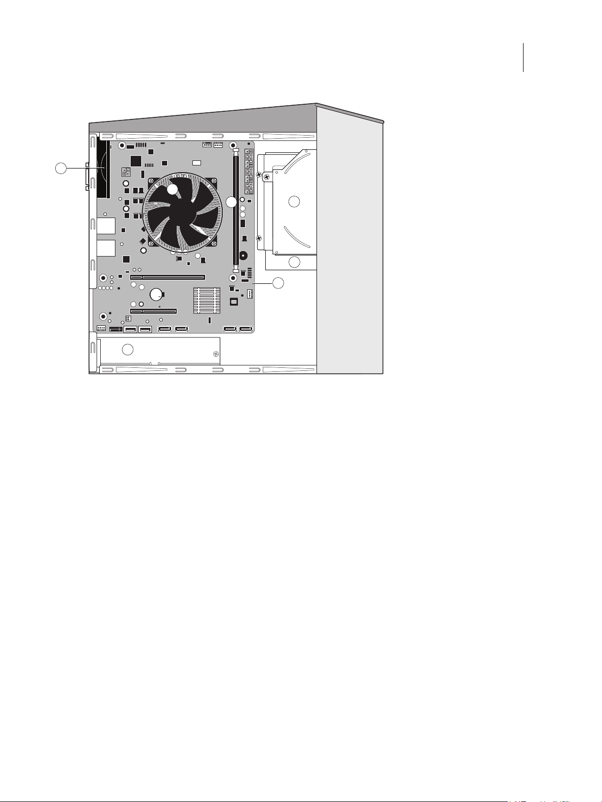
Figure 3: Internal side view
1 Power supply 5 DVD drive
2 DIMM slots 6 Hard disk drive
3 CPU cooling assembly 7 Motherboard
4 Chassis fan
Note: Cables, UIB, or front panel USB port are not shown.
1
2
3
4
5
6
7
19Service Guide: Fiery Central Solo for KM
Service Procedures
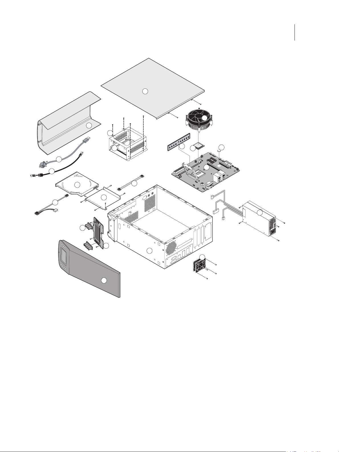
Figure 4: Exploded view of FC Solo components
1 Front panel 7 CPU 13 Top panel 19 DVD drive power/data
combo cable
2 Hard disk drive bracket 8 Battery 14 UIB
3 Hard disk drive 9 Motherboard 15 UIB buttons 20 UIB cable
4 Side panel 10 Power supply 16 Hard disk drive SATA cable 21 Front panel USB port and
cable
5 DIMM 11 Chassis fan 17 DVD drive bracket
6 CPU cooling assembly 12 Chassis 18 DVD drive
Note: Tie-wraps, cable clamps, dongle(s), or external cables are not shown.
1
2
3
4
5
6
78
9
10
11
12
13
14
15
16
17
18
19
20
21

20Service Guide: Fiery Central Solo for KM
Service Procedures
Figure 5: Data cable connections in the FC Solo
Cable key From To
1 Front panel USB port cable Front panel USB port Motherboard USB_A2 connector
2 UIB cable User Interface Board Motherboard USB_A1 connector
3 DVD drive power/data combo cable DVD drive Motherboard SATA_6G_0 connector
4 Hard disk drive data cable Hard disk drive Motherboard SATA_6G_1 connector
32
1
41
2
3
4
Table of contents
Other EFI Desktop manuals


