S&T kontron KBox B-201-CFL User manual


KBox B-201-CFL - User Guide, Rev 1.3
www.kontron.com // 3
KBOX B
-201-CFL - USER GUIDE
Disclaimer
Kontron would like to point out that the information contained in this user guide may be subject to alteration,
particularly as a result of the constant upgrading of Kontron products. This document does not entail any guarantee
on the part of Kontron with respect to technical processes described in the user guide or any product characteristics
set out in the user guide. Kontron assumes no responsibility or liability for the use of the described product(s),
conveys no license or title under any patent, copyright or mask work rights to these products and makes no
representations or warranties that these products are free from patent, copyright or mask work right infringement
unless otherwise specified. Applications that are described in this user guide are for illustration purposes only.
Kontron makes no representation or warranty that such application will be suitable for the specified use without
further testing or modification. Kontron expressly informs the user that this user guide only contains a general
description of processes and instructions which may not be applicable in every individual case. In cases of doubt,
please contact Kontron.
This user guide is protected by copyright. All rights are reserved by Kontron. No part of this document may be
reproduced, transmitted, transcribed, stored in a retrieval system, or translated into any language or computer
language, in any form or by any means (electronic, mechanical, photocopying, recording, or otherwise), without the
express written permission of Kontron. Kontron points out that the information contained in this user guide is
constantly being updated in line with the technical alterations and improvements made by Kontron to the products
and thus this user guide only reflects the technical status of the products by Kontron at the time of publishing.
Brand and product names are trademarks or registered trademarks of their respective owners.
©2019 by Kontron Europe GmbH
Kontron Europe GmbH
Gutenbergstraße 2
85737 Ismaning
Germany
www.kontron.com

KBox B-201-CFL - User Guide, Rev 1.3
www.kontron.com // 4
Intended Use
This embedded Box PC, sold by Kontron, is part of Kontron’s B-Series intended for high performance, small form-
factor needs with long-term availability. The product can operate in a temperature range from 0°C to plus 45°C; the
storage elements can withstand temperatures from minus 20°C to plus 80°C, and a humidity of 10 to 93 percent does
not affect the function of the product. The KBox B-201-CFL’s typical application areas are image processing tasks,
plant data collection, as well as manufacturing executive systems (MES). This product’s various mounting options
guarantee flexibility for multiple user cases, behind a monitor, horizontal and vertical wall mounting or as desktop
version as described in this user guide. Users must comply with all product specifications stated in the product
documentation and this user guide. If it is intended, to incorporated the product into any total systems or applications,
please carry out sufficient, compatibility and functions tests prior to any use or resale.
THIS PRODUCT IS NOT DESIGNED, MANUFACTURED OR INTENDED FOR USE OR RESALE FOR THE
OPERATION OF APPLICATION IN A HAZARDOUS ENVIRONMENT, OR REQUIRING FAIL-SAFE PERFORMANCE,
OR IN WHICH THE FAILURE OF PRODUCTS COULD LEAD DIRECTLY TO DEATH, PERSONAL INJURY, OR SEVERE
PHYSICAL OR ENVIRONMENTAL DAMAGE (COLLECTIVELY "HIGH RISK APPLICATIONS").
You understand and agree that your use of Kontron products as a component in High Risk Applications is entirely at
your own risk. To minimize the risks associated with your systems and applications, you must provide adequate
design and operating safeguards. You are responsible to ensure that your systems (and any Kontron hardware or
software products incorporated in your systems) meet all applicable requirements. Unless otherwise stated in the
product documentation, the Kontron product is not provided with error-tolerance capabilities and therefore cannot
be deemed as being engineered, manufactured or setup to be compliant for implementation or for resale as a
component in High Risk Applications. All application and safety related information in this document (including
application descriptions, suggested safety measures, suggested Kontron products, and other materials) is provided
for reference only.

KBox B-201-CFL - User Guide, Rev 1.3
www.kontron.com // 5
Revision History
Revision Brief Description of Changes Date of Issue Author/
Editor
1.0 Initial version 2019-June-14 CW
1.1 Updated product figure (new power button), Ch. 10.2 added 9th Gen. Intel®
Core™ i3/i5/i7 and in Ch. 1 replaced EN 60950-1 with EN 62368-1,
expanded Ch. 12.2.1 BIOS Update info & Included a uEFI BIOS only info note.
2020-Feb-18 CW
1.2 Include Ch. 8.5 Wi-Fi Antenna and Ch. 10.6.2 Power Protection information. 2020-Mar-05 CW
1.3 Added new 24 VDC variant and updated Ch. 3.4 Accessories, Ch. 3.5 Type
Label and General Safety Instructions.
2020-Dec-16 CW
Terms and Conditions
Kontron warrants products in accordance with defined regional warranty periods. For more information about
warranty compliance and conformity, and the warranty period in your region, visit http://www.kontron.com/terms-
and-conditions.
Kontron sells products worldwide and declares regional General Terms & Conditions of Sale, and Purchase Order
Terms & Conditions. Visit http://www.kontron.com/terms-and-conditions.
For contact information, refer to the corporate offices contact information on the last page of this user guide or visit
our website CONTACT US.
Customer Support
Find Kontron contacts by visiting: http://www.kontron.com/support.
Customer Service
As a trusted technology innovator and global solutions provider, Kontron extends its embedded market strengths into
a services portfolio allowing companies to break the barriers of traditional product lifecycles. Proven product
expertise coupled with collaborative and highly-experienced support enables Kontron to provide exceptional peace of
mind to build and maintain successful products.
For more details on Kontron’s service offerings such as: enhanced repair services, extended warranty, Kontron
training academy, and more visit http://www.kontron.com/support-and-services/services.
Customer Comments
If you have any difficulties using this user guide, discover an error, or just want to provide some feedback, contact
Kontron Support. Detail any errors you find. We will correct the errors or problems as soon as possible and post the
revised user guide on our website.
KBox B-201-CFL - User Guide, Rev 1.3
www.kontron.com // 6
Symbols
The following symbols may be used in this user guide
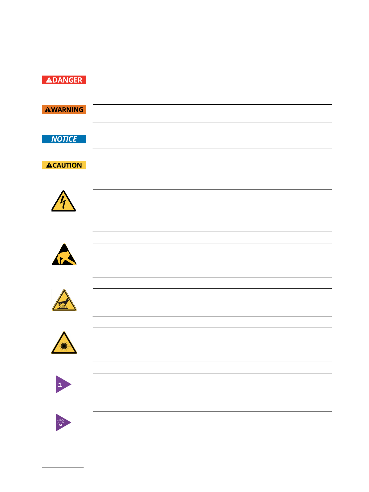
DANGER indicates a hazardous situation which, if not avoided,
will result in death or serious injury.
WARNING indicates a hazardous situation which, if not avoided,
could result in death or serious injury.
NOTICE indicates a property damage message.
CAUTION indicates a hazardous situation which, if not avoided,
may result in minor or moderate injury.
Electric Shock!
This symbol and title warn of hazards due to electrical shocks (> 60
V) when touching
products or parts of products. Failure to observe the precautions indicated and/or
prescribed by the law may endanger your life/health and/or result in damage to your
material.
ESD Sensitive Device!
This symbol and title inform that the electronic boards and their components are sensitive
to static electricity. Care must therefore
be taken during all handling operations and
inspections of this product in order to ensure product integrity at all times.
HOT Surface!
Do NOT touch! Allow to cool before servicing.
Laser!
This symbol inform of the risk of exposure to laser beam and light emitting devices (LEDs)
from an electrical device. Eye protection per manufacturer notice shall review before
servicing.
This symbol indicates general information about the product and the user guide.
This symbol also indicates detail information about the specific product configuration.
This symbol precedes helpful hints and tips for daily use.
KBox B-201-CFL – User Guide, Rev 1.3
www.kontron.com // 7
For Your Safety
Your new Kontron product was developed and tested carefully to provide all features necessary to ensure its
compliance with electrical safety requirements. It was also designed for a long fault-free life. However, the life
expectancy of your product can be drastically reduced by improper treatment during unpacking and installation.
Therefore, in the interest of your own safety and of the correct operation of your new Kontron product, you are
requested to conform with the following guidelines.
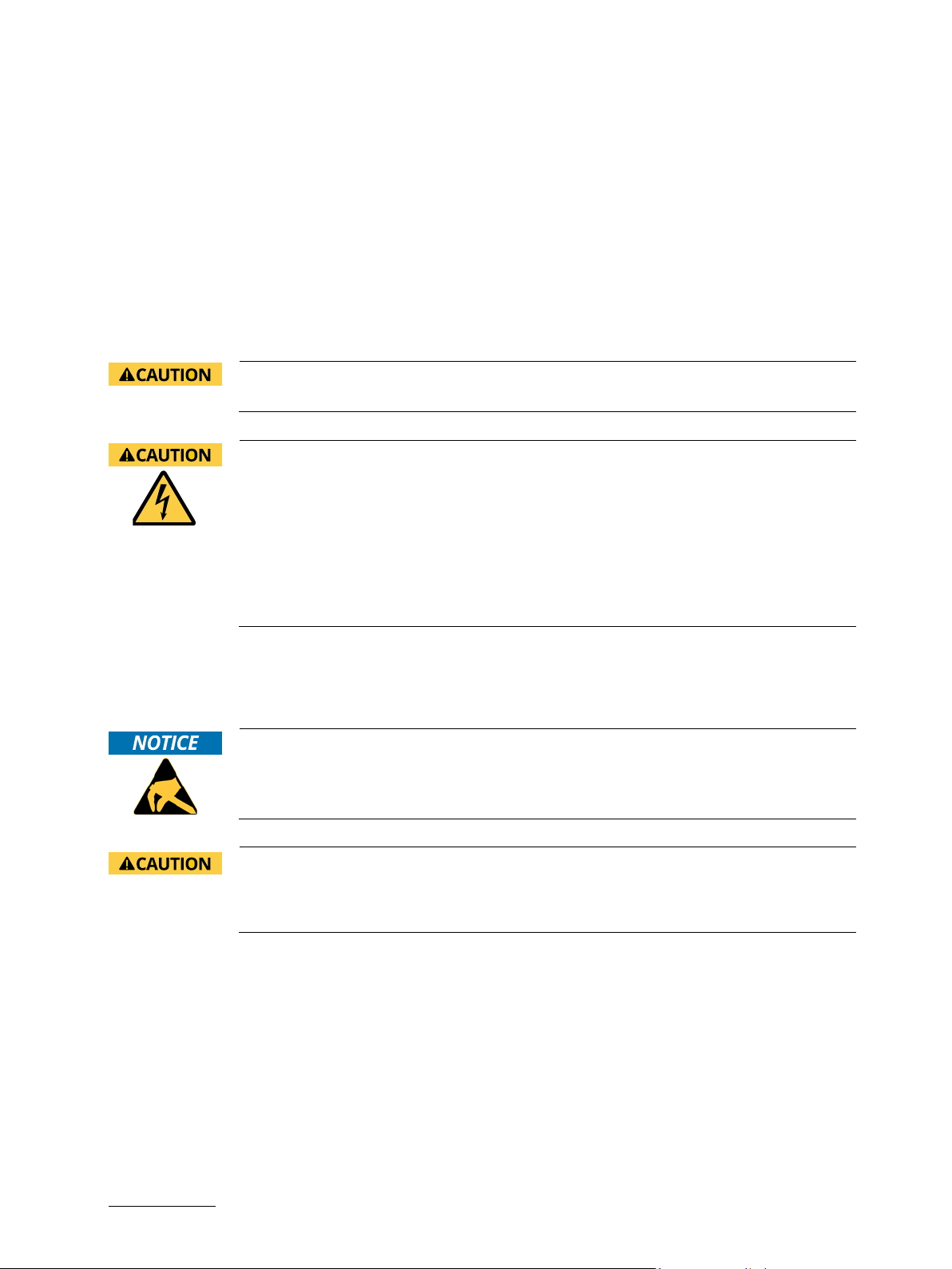
High Voltage Safety Instructions
As a precaution and in case of danger, the power connector must be easily accessible. The power connector is the
product’s main disconnect device.
Warning
All operations on this product must be carried out by sufficiently skilled personnel only.
Electric Shock!
Before installing a non hot-swappable Kontron product into a system always ensure that
your mains power is switched off. This also applies to the installation of piggybacks. Serious
electrical shock hazards can exist during all installation, repair, and maintenance operations
on this product. Therefore, always unplug the power cable and any other cables which
provide external voltages before performing any work on this product.
Earth ground connection to vehicle’s chassis or a central grounding point shall remain
connected. The earth ground cable shall be the last cable to be disconnected or the first
cable to be connected when performing installation or removal procedures on this product.
Special Handling and Unpacking Instruction
ESD Sensitive Device!
Electronic boards and their components are sensitive to static electricity. Therefore, care
must be taken during all handling operations and inspections of this product, in order to
ensure product integrity at all times.
Handling and operation of the product is permitted only for trained personnel aware of the
associated dangers, within a work place that is access controlled and fulfills all necessary
technical and environmental requirements. Follow the “General Safety Instructions”
supplied with the product.
Do not handle this product out of its protective enclosure while it is not used for operational purposes unless it is
otherwise protected.
Whenever possible, unpack or pack this product only at EOS/ESD safe work stations. Where a safe work station is not
guaranteed, it is important for the user to be electrically discharged before touching the product with his/her hands
or tools. This is most easily done by touching a metal part of your system housing.
It is particularly important to observe standard anti-static precautions when changing piggybacks, ROM devices,
jumper settings etc. If the product contains batteries for RTC or memory backup, ensure that the product is not placed
on conductive surfaces, including anti-static plastics or sponges. They can cause short circuits and damage the
batteries or conductive circuits on the product.

KBox B-201-CFL - User Guide, Rev 1.3
www.kontron.com // 8
Lithium Battery Precautions
If your product is equipped with a lithium battery, take the following precautions when replacing the battery.
Danger of explosion if the battery is replaced incorrectly.
Replace only with same or equivalent battery type recommended by the manufacturer.
Dispose of used batteries according to the manufacturer’s instructions.
General Instructions on Usage
In order to maintain Kontron’s product warranty, this product must not be altered or modified in any way. Changes or
modifications to the product, that are not explicitly approved by Kontron and described in this user guide or received
from Kontron Support as a special handling instruction, will void your warranty.
This product should only be installed in or connected to systems that fulfill all necessary technical and specific
environmental requirements. This also applies to the operational temperature range of the specific board version
that must not be exceeded.
In performing all necessary installation and application operations, only follow the instructions supplied by the
present user guide.
Keep all the original packaging material for future storage or warranty shipments. If it is necessary to store or ship
the product then re-pack it in the same manner as it was delivered.
Special care is necessary when handling or unpacking the product. See Special Handling and Unpacking Instruction.
Quality and Environmental Management
Kontron aims to deliver reliable high-end products designed and built for quality, and aims to complying with
environmental laws, regulations, and other environmentally oriented requirements. For more information regarding
Kontron’s quality and environmental responsibilities, visit http://www.kontron.com/about-kontron/corporate-
responsibility/quality-management.
Disposal and Recycling
Kontron’s products are manufactured to satisfy environmental protection requirements where possible. Many of the
components used are capable of being recycled. Final disposal of this product after its service life must be
accomplished in accordance with applicable country, state, or local laws or regulations.
WEEE Compliance
The Waste Electrical and Electronic Equipment (WEEE) Directive aims to:
Reduce waste arising from electrical and electronic equipment (EEE)
Make producers of EEE responsible for the environmental impact of their products, especially when the product
become waste
Encourage separate collection and subsequent treatment, reuse, recovery, recycling and sound environmental
disposal of EEE
Improve the environmental performance of all those involved during the lifecycle of EEE
Environmental protection is a high priority with Kontron.
Kontron follows the WEEE directive.

KBox B-201-CFL - User Guide, Rev 1.3
www.kontron.com // 9
Table of Contents
Symbols.................................................................................................................................................................................................................6
For Your Safety ...................................................................................................................................................................................................7
High Voltage Safety Instructions ..................................................................................................................................................................7
Special Handling and Unpacking Instruction ............................................................................................................................................7
Lithium Battery Precautions.......................................................................................................................................................................... 8
General Instructions on Usage..................................................................................................................................................................... 8
Quality and Environmental Management................................................................................................................................................ 8
Disposal and Recycling.................................................................................................................................................................................... 8
WEEE Compliance.............................................................................................................................................................................................. 8
Table of Contents...............................................................................................................................................................................................9
List of Tables ......................................................................................................................................................................................................11
List of Figures.....................................................................................................................................................................................................11
1/ General Safety Instructions ...........................................................................................................................................................13
1.1. Electrostatic Discharge (ESD)................................................................................................................................................................14
1.1.1. Grounding Methods................................................................................................................................................................................14
1.2. Instructions for the Lithium Battery...................................................................................................................................................14
2/ Introduction .........................................................................................................................................................................................15
3/ Scope of Delivery ...............................................................................................................................................................................16
3.1. Packaging.....................................................................................................................................................................................................16
3.2. Unpacking....................................................................................................................................................................................................16
3.3. Scope of Delivery......................................................................................................................................................................................16
3.4. Accessories ................................................................................................................................................................................................16
3.5. Product Identification Type Label .......................................................................................................................................................17
4/ Product Features................................................................................................................................................................................18
4.1. Front Side Features..................................................................................................................................................................................19
4.1.1. Front Connectors and Buttons ..........................................................................................................................................................19
4.2. Rear Side Features..................................................................................................................................................................................20
4.2.1. Rear Panel Connectors ........................................................................................................................................................................21
4.3. Left and Right Side Features ...............................................................................................................................................................24
4.4. Top Cover and Bottom Side Features............................................................................................................................................... 25
5/ System Extension .............................................................................................................................................................................26
5.1. External Storage.......................................................................................................................................................................................26
5.1.1. 2.5” SSD Drive Bay .................................................................................................................................................................................26
5.2. Internal Expansion ..................................................................................................................................................................................26
5.2.1. mPCIE Socket..........................................................................................................................................................................................26
5.2.2. M.2 Socket .............................................................................................................................................................................................. 27
6/ Accessing Internal Components..................................................................................................................................................28
6.1. Opening and Closing the Chassis........................................................................................................................................................28
6.2. Opening and Closing SSD Drive Bay Cover......................................................................................................................................30
6.2.1. Installing and Removing Externally Accessible 2.5” SSD .........................................................................................................31
6.3. Installing and Removing Internal M.2 SSD......................................................................................................................................32
6.4. Installing and Removing Internal mPCIe Expansion Card.......................................................................................................... 32
7/ Thermal Considerations .................................................................................................................................................................34
7.1. Active Cooling ............................................................................................................................................................................................34
7.2. Minimum System Clearance (Keep out Area) ................................................................................................................................ 35
7.3. Third Party Components ....................................................................................................................................................................... 35

KBox B-201-CFL - User Guide, Rev 1.3
www.kontron.com // 10
8/ Installation Instructions.................................................................................................................................................................36
8.1. Chassis Feet............................................................................................................................................................................................... 37
8.1.1. Chassis Feet Mount Option................................................................................................................................................................ 37
8.2. Vertical Stand (Option)..........................................................................................................................................................................38
8.2.1. Vertical Stand Mount Options ..........................................................................................................................................................38
8.3. Mounting Brackets (Option) ................................................................................................................................................................39
8.3.1. Mounting brackets Mount Options..................................................................................................................................................41
8.4. VESA 100 Mount Assembly (Option).................................................................................................................................................42
8.4.1. VESA 100 Mount Options ...................................................................................................................................................................44
8.5. Connecting the Wi-Fi Antenna (option) ...........................................................................................................................................46
9/ Starting Up...........................................................................................................................................................................................47
9.1. Connecting the External Power Connection ...................................................................................................................................47
9.1.1. 12 VDC AC/DC Power Supply..............................................................................................................................................................47
9.2. 24 VDC Wired Power Cable ..................................................................................................................................................................47
9.3. Power On/Off Procedure......................................................................................................................................................................49
9.3.1. Forced Shutdown..................................................................................................................................................................................49
9.4. Operating System (OS) and Hardware Component Drivers......................................................................................................49
10/ Technical Data ...................................................................................................................................................................................50
10.1. Block Diagrams .......................................................................................................................................................................................50
10.2. Technical Specification........................................................................................................................................................................ 52
10.3. Mechanical Specification ....................................................................................................................................................................54
10.3.1. Dimension Diagrams – KBox B-201-CFL .....................................................................................................................................54
10.3.2. Dimension Diagrams- Wall Mount Brackets ............................................................................................................................ 56
10.4. Environmental Specification .............................................................................................................................................................56
10.5. Directives and Standards.................................................................................................................................................................... 56
10.6. Power Specification..............................................................................................................................................................................58
10.6.1. 12 VDC .....................................................................................................................................................................................................58
10.6.2. 24 VDC (optional variant)................................................................................................................................................................58
10.6.3. Power Protection ............................................................................................................................................................................... 59
10.6.4. Power Consumption..........................................................................................................................................................................59
10.6.5. Ground ...................................................................................................................................................................................................59
11/ External Interface - Pin Assignments........................................................................................................................................60
11.1. DC-IN Power Connector Pin Assignment ........................................................................................................................................60
11.2. USB 3.1 Gen 1 Port & USB 3.1 Gen 2 Pin Assignment....................................................................................................................60
11.3. USB 2.0 Port Pin Assignment...............................................................................................................................................................61
11.4. LAN GbE Connector Pin Assignment .................................................................................................................................................61
11.5. Display Port (DP) V1.2 Connector Pin Assignment.......................................................................................................................62
11.6. DVI-D Connector Pin Assignment .....................................................................................................................................................62
11.7. PS/2 Keyboard Connector Pin Assignment.................................................................................................................................... 63
11.8. PS/2 Mouse Connector Pin Assignment.........................................................................................................................................63
11.9. Audio Line-out and Audio Line-in Connector Pin Assignment ................................................................................................ 63
11.10. Serial Port Connector Pin Assignment ..........................................................................................................................................64
12/ BIOS........................................................................................................................................................................................................ 65
12.1. Starting the uEFI BIOS ...........................................................................................................................................................................65
12.2. BIOS Update.............................................................................................................................................................................................66
12.2.1. Performing a BIOS Update ...............................................................................................................................................................66
13/ Technical Support.............................................................................................................................................................................68
13.1. Returning Defective Merchandise ....................................................................................................................................................68
14/ Storage, Transportation and Maintenance .............................................................................................................................69

KBox B-201-CFL - User Guide, Rev 1.3
www.kontron.com // 11
14.1. Storage.......................................................................................................................................................................................................69
14.2. Transportation .......................................................................................................................................................................................69
14.3. Maintenance............................................................................................................................................................................................69
14.3.1. Replacing Lithium Battery................................................................................................................................................................69
15/ Warranty ..............................................................................................................................................................................................70
15.1. Limitation/Exemption from Warranty Obligation....................................................................................................................... 70
About Kontron .................................................................................................................................................................................................. 72
List of Tables
Table 1: Scope of Delivery ..............................................................................................................................................................................16
Table 2: Accessories........................................................................................................................................................................................16
Table 3: Mainboard Specification............................................................................................................................................................... 52
Table 4: Processor Specification................................................................................................................................................................ 52
Table 5: Storage Specification..................................................................................................................................................................... 52
Table 6: Interface Specifications................................................................................................................................................................ 53
Table 7: Software Specification.................................................................................................................................................................. 53
Table 8: Mechanical Specifications...........................................................................................................................................................54
Table 9: Environmental Specification....................................................................................................................................................... 56
Table 10: Directives and Standards Compliance....................................................................................................................................57
Table 11: External AC/DC power supply...................................................................................................................................................58
Table 12: External Power Supply 24 VDC (variant) ..............................................................................................................................58
Table 13: External AC/DC Power Supply Protection Features.......................................................................................................... 59
Table 14: Power Consumption Estimation .............................................................................................................................................. 59
Table 15: DC power Jack Pin Assignment.................................................................................................................................................60
Table 16: USB 3 (Type A) Pin Assignment................................................................................................................................................60
Table 17: USB 2.0 Connector Pin Assignment..........................................................................................................................................61
Table 18: LAN (GbE) Connector Pin Assignment.....................................................................................................................................61
Table 19: LAN Link Activity .............................................................................................................................................................................61
Table 20: Display Port (DP) Connector Pin Assignment ..................................................................................................................... 62
Table 21: DVI-D Connector Pin Assignment ............................................................................................................................................ 62
Table 22: PS/2 Keyboard Connector Pin Assignment .........................................................................................................................63
Table 23: PS/2 Mouse Connector Pin Assignment...............................................................................................................................63
Table 24: Audio Line-out Audio Line-in Pin Assignment.................................................................................................................... 63
Table 25: Serial Interface COM1 port (RS232) Connector Pin Assignment...................................................................................64
Table 26: Navigation Hot Keys Available in the Legend Bar..............................................................................................................66
Table 27: List of Acronyms............................................................................................................................................................................71
List of Figures
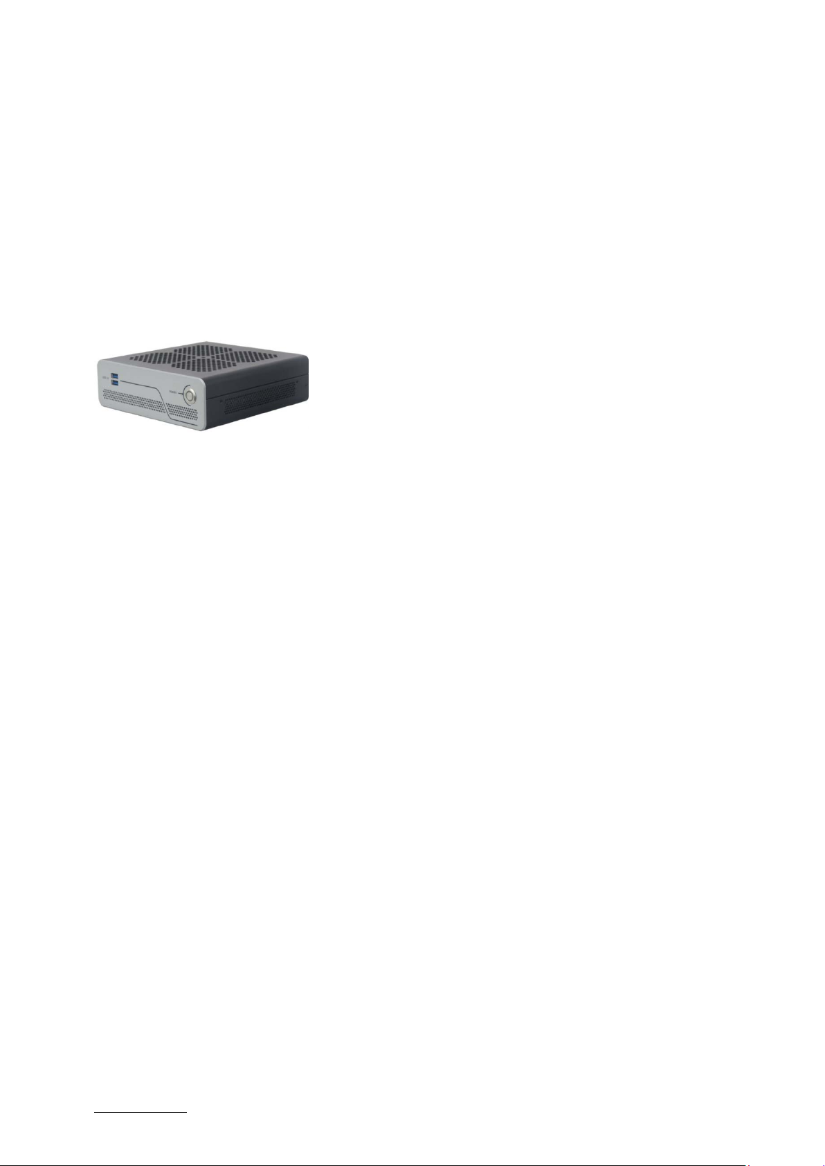
Figure 1: KBox B-201-CFL ...............................................................................................................................................................................15
Figure 2: Type Label.........................................................................................................................................................................................17
Figure 3: KBox B-201-CFL Overview...........................................................................................................................................................18
Figure 4: Front Side..........................................................................................................................................................................................19
Figure 5: Rear Panel KBox B-201-CFL (Smart).......................................................................................................................................20
Figure 6: Rear Panel KBox B-201-CFL (Value).........................................................................................................................................21
Figure 7: Left Side and Right Side Views..................................................................................................................................................24
Figure 8: Top View........................................................................................................................................................................................... 25
Figure 9: Bottom View.................................................................................................................................................................................... 25
Figure 10: Top Cover Fastening Screws ...................................................................................................................................................29
Figure 11: Holding Brackets...........................................................................................................................................................................29
Figure 12: SSD Drive Bay Cover Rear Side................................................................................................................................................30
Figure 13: SSD Drive Bay Cover Top Side..................................................................................................................................................30
Figure 14: SSD Drive Bay with SSD..............................................................................................................................................................31

KBox B-201-CFL - User Guide, Rev 1.3
www.kontron.com // 12
Figure 15: Air-intake Ventilation Openings..............................................................................................................................................34
Figure 16: Air-output Ventilation Openings ............................................................................................................................................34
Figure 17: Position of Chassis Feet............................................................................................................................................................. 37
Figure 18: Chassis Feet Mount Option ...................................................................................................................................................... 37
Figure 19: Vertical Stand................................................................................................................................................................................38
Figure 20: Vertical Stand Screws ...............................................................................................................................................................38
Figure 21: Vertical Stand Mount Options .................................................................................................................................................38
Figure 22: Mounting Bracket........................................................................................................................................................................39
Figure 23: Keep Out Areas – with Top Cover facing the Mount Surface .......................................................................................40
Figure 24: Keep Out Areas – with Bottom Side facing the Mount Surface...................................................................................40
Figure 25: Mounting Brackets Desktop Mount Options.......................................................................................................................41
Figure 26: Mounting Brackets Wall Mount Options..............................................................................................................................41
Figure 27: VESA Mounting Assembly Kit..................................................................................................................................................42
Figure 28: KBox B-201-CFL Mounting Position......................................................................................................................................42
Figure 29: Inserting the Band ......................................................................................................................................................................43
Figure 30: Positioning the Power Supply.................................................................................................................................................43
Figure 31: KBox B-201-CFL and Power Supply Mounting Position..................................................................................................43
Figure 32: Non VESA Stand Monitor Assembly......................................................................................................................................44
Figure 33: Installed VESA 100 Mount Assembly – non VESA Stand Monitor...............................................................................44
Figure 34: VESA Monitor Stand Assembly...............................................................................................................................................45
Figure 35: Installed VESA 100 Mount Assembly – non VESA Stand Monitor ...............................................................................45
Figure 36: 24 VDC Wired Power Cable......................................................................................................................................................48
Figure 37: Block Diagram of KBox B-201-CFL Smart Variant............................................................................................................50
Figure 38: Block Diagram of KBox B-201-CFL Value Variant .............................................................................................................51
Figure 39: Dimensions Front Panel............................................................................................................................................................54
Figure 40: Dimensions Rear Panel.............................................................................................................................................................54
Figure 41: Dimensions Top Cover ............................................................................................................................................................... 55
Figure 42: Dimensions Bottom Side.......................................................................................................................................................... 55
Figure 43: Dimensions Right Side and Left Side.................................................................................................................................... 55
Figure 44: Dimensions with Mounting Brackets................................................................................................................................... 56

KBox B-201-CFL - User Guide, Rev 1.3
www.kontron.com // 13
1/ General Safety Instructions
Please read this passage carefully and take careful note of the instructions, which have been compiled for your safety
and to ensure to apply in accordance with intended regulations. If the following general safety instructions are not
observed, it could lead to injuries to the operator and/or damage of the product; in cases of non-observance of the
instructions Kontron Europe is exempt from accident liability, this also applies during the warranty period.
The product has been built and tested according to the basic safety requirements for low voltage (LVD) applications
and has left the manufacturer in safety-related, flawless condition. To maintain this condition and to also ensure safe
operation, the operator must not only observe the correct operating conditions for the product but also the following
general safety instructions:
The product must be used as specified in the product documentation, in which the instructions for safety for the
product and for the operator are described. These contain guidelines for setting up, installation and assembly,
maintenance, transport or storage.
The on-site electrical installation must meet the requirements of the country's specific local regulations.
If a power cable comes with the product, only this cable should be used. Do not use an extension cable to connect
the product.
To guarantee that sufficient air circulation is available to cool the product, please ensure that the ventilation
openings are not covered or blocked. If a filter mat is provided, this should be cleaned regularly. Do not place the
product close to heat sources or damp places. Make sure the product is well ventilated.
Only connect the product to an external power supply providing the voltage type (AC or DC) and the input power
(max. current) specified on the Kontron Product Label and meeting the requirements of the Limited Power Source
(LPS) and Power Source (PS2) of UL/IEC 62368-1 .
Only products or parts that meet the requirements for Power Source (PS1) of UL/IEC 62368-1 may be connected
to the product’s available interfaces (I/O).
Before opening the product, make sure that the product is disconnected from the mains.
Switching off the product by its power button does not disconnect it from the mains. Complete disconnection is
only possible if the power cable is removed from the wall plug or from the product. Ensure that there is free and
easy access to enable disconnection.
The product may only be opened for the insertion or removal of add-on cards (depending on the configuration of
the product). This may only be carried out by qualified operators.
If extensions are being carried out, the following must be observed:
all effective legal regulations and all technical data are adhered to
the power consumption of any add-on card does not exceed the specified limitations
the current consumption of the product does not exceed the value stated on the product label
Only original accessories that have been approved by Kontron Europe can be used.
Please note: safe operation is no longer possible when any of the following applies:
the product has visible damages or
the product is no longer functioning
In this case the product must be switched off and it must be ensured that the product can no longer be
operated.
Handling and operation of the product is permitted only for trained personnel within a work place that is access
controlled.
CAUTION: Risk of explosion if the battery is replaced incorrectly (short-circuited, reverse-poled, wrong battery
type). Dispose of used batteries according to the manufacturer’s instructions.
This product is not suitable for use in locations where children are likely to be present
Additional Safety Instructions for DC Power Supply Circuits
To guarantee safe operation, please observe that:
the external DC power supply must meet the criteria for LPS and PS2 (UL/IEC 62368-1)
no cables or parts without insulation in electrical circuits with dangerous voltage or power should be
touched directly or indirectly
a reliable protective earthing connection is provided
a suitable, easily accessible disconnecting device is used in the application (e.g. overcurrent protective
device), if the product itself is not disconnect able
a disconnect device, if provided in or as part of the product, shall disconnect both poles simultaneously

KBox B-201-CFL - User Guide, Rev 1.3
www.kontron.com // 14
interconnecting power circuits of different products cause no electrical hazards
A sufficient dimensioning of the power cable wires must be selected – according to the maximum electrical
specifications on the product label – as stipulated by EN62368-1 or VDE0100 or EN60204 or UL61010-1
regulations.
1.1. Electrostatic Discharge (ESD)
A sudden discharge of electrostatic electricity can destroy static-sensitive devices or micro-
circuitry.
Proper packaging and grounding techniques are necessary precautions to prevent damage. Always take the following
precautions:
1. Transport boards in ESD-safe containers such as boxes or bags.
2. Keep electrostatic sensitive parts in their containers until they arrive at the ESD-safe workplace.
3. Always be properly grounded when touching a sensitive board, component, or assembly.
4. Store electrostatic-sensitive boards in protective packaging or on antistatic mats.
1.1.1. Grounding Methods
By adhering to the guidelines below, electrostatic damage to the product can be avoided:
1. Cover workstations with approved antistatic material. Always wear a wrist strap connected to workplace.
Always use properly grounded tools and equipment.
2. Use antistatic mats, heel straps, or air ionizers for more protection.
3. Always handle electrostatically sensitive components by their edge or by their casing.
4. Avoid contact with pins, leads, or circuitry.
5. Turn off power and input signals before inserting and removing connectors or connecting test equipment.
6. Keep work area free of non-conductive materials such as ordinary plastic assembly aids and Styrofoam.
7. Use only field service tools that are conductive, such as cutters, screwdrivers, and vacuum cleaners.
8. Always place drives and boards PCB-assembly-side down on the foam.
1.2. Instructions for the Lithium Battery
The KBox B-201-CFL’s mainboard is equipped with a lithium battery. When replacing the battery observe the
instructions in Chapter 14.3.1: Replacing Lithium Battery.
Danger of explosion when replacing with wrong type of battery. Replace only with the same
or equivalent type recommended by the manufacturer. The lithium battery type must be UL
recognized.
Do not dispose of lithium batteries in general trash collection. Dispose of the battery
according to the local regulations dealing with the disposal of these special materials, (e.g.
to the collecting points for dispose of batteries).
KBox B-201-CFL - User Guide, Rev 1.3
www.kontron.com // 15
2/ Introduction
This user guide describes the KBox B-201-CFL made by Kontron and focuses on describing the KBox B-201-CFL’s
special features. New users are recommended to study the installation instructions within this user guide before
switching on the power.
The KBox B-201-CFL is a small form factor high performance Box PC family with 8th / 9th Gen. Intel Core™ platforms
and mini ITX mainboard variants ‘Smart’ and ‘Value’, both offering a wide variety of external interfaces on the rear
panel. System expansion is achieved internally with a M.2 Key M socket and mPCIe full size/half size socket, and
externally with a 2.5” SSD drive bay. A external 12 VDC AC/DC power supply powers the standard KBox B-201-CFL and
for industrial applications a 24 VDC power supply variant is available. All product variants are available in a robust
metal chassis that guarantees flexibility in multiple user applications such as behind a monitor, horizontal and
vertical wall mounting, or as a movable or fixed desktop version.
Figure 1: KBox B-201-CFL
General Smart and Value features are:
KBox B-201-CFL (Smart) KBox B-201-CFL (Value)
8th / 9th Gen. Intel® Core™ i3/i5/i7
Chipset Intel® Q370 or Chipset Intel® H310
Up to 32 GB DDR4-2666 UDIMM with dual SODIMM sockets
Memory Expansion
2.5” SSD drive bay (external)
M.2 (internal)
External Rear Interfaces or External Rear Interfaces
2x LAN
4x USB 2.0
2x USB 3.1 Gen 1
2x USB3.1 Gen 2
2x DP V1.2
1x DVI-D
1x Audio line-in, 1x Audio line-out
1x PS/2 keyboard, 1x PS/2 mouse
1x Serial port
2x LAN
3x USB 2.0
2x USB 3.1 Gen 1
1x DP V1.2
1x DVI-D
1x Audio line In and 1x Audio line-out
1x PS/2 keyboard, 1x PS/2 mouse
1x Serial port
External front interfaces: 2x USB 3.1 Gen 1
Active fan cooling
Low noise
Power: 12 VDC with external AC/DC power supply
Additional Variant:
24 VDC with wired cable
Options:
Wi-Fi Dual band (2.4 GHz/5 GHz), BT 4.1 with Dual Wi-Fi antenna
Kontron APPROTECT

KBox B-201-CFL - User Guide, Rev 1.3
www.kontron.com // 16
3/ Scope of Delivery
3.1. Packaging
The KBox B-201-CFL is packaged together with all parts, in a product specific cardboard package designed to provide
adequate protection and absorb shock.
3.2. Unpacking
To unpack the KBox B-201-CFL, perform the following:
1. Remove packaging.
2. Do not discard the original packaging. Keep the original packaging for future transportation or storage.
3. Check the delivery for completeness by comparing the delivery with the original order.
4. Keep the associated paperwork. It contains important information for handling the product.
5. Check the product for visible shipping damage.
If you notice any shipping damage or inconsistencies between the contents and the original order, contact your
dealer.
3.3. Scope of Delivery
Check that the delivery is complete, and contains the items listed below. If you discover damaged or missing items,
contact your dealer. Each Kontron product is delivered with a General Safety Instructions sheet, Kontron recommends
users to keep this sheet for future reference. Additionally, the General Safety Instructions are contained within this
user guide and available as a download from the product’s web page.
Table 1: Scope of Delivery
Product Description
KBox B-201-CFL Smart 12 VDC 1x KBox B -201-CFL with D3633-S mITX mainboard and Intel® Q370 chipset
1x External 12 VDC Power Supply & regional mains power cable and
4x Adhesive Chassis feet
KBox B-201-CFL Value 12 VDC 1x KBox B-201-CFL with D3634-S mITX mainboard and Intel® H310 chipset and
1x External 12 VDC Power Supply & regional mains power cable
4x Adhesive chassis feet
KBox B-201-CFL Smart 24 VDC 1x KBox B -201-CFL with D3633-S mITX mainboard and Intel® Q370 chipset
1x External 24 VDC wired power cable
4x Adhesive Chassis feet
KBox B-201-CFL Value 24 VDC 1x KBox B -201-CFL with D3633-S mITX mainboard and Intel® Q370 chipset
1x External 12 VDC Power Supply & regional mains power cable
4x Adhesive Chassis feet
Due to additional internal components in the 24 VDC variant, the 12 VDC and optional 24 VDC
variant are not interchangeable.
3.4. Accessories
Table 2: Accessories
Part Number Part Part Description
1065 3431 Vertical Stand Kit Metal stand and two screws (M3x6)
1065 3430 Wall Mount Set Two wall mount brackets and four screws (M3x6)
1062 5317 VESA Mount Kit VESA 100 mounting frame, hook & loop flexible band, 4x screws
(M3x 8 mm), 4x screws (M4x 20 mm) and 4x spacers

KBox B-201-CFL - User Guide, Rev 1.3
www.kontron.com // 17
3.5. Product Identification Type Label
The type label defines the product’s mainboard variants Smart or Value and the power variant 12 VDC or 24 VDC, and
contains specific product information (Model, Power Product Number, Serial Number, Electrical Specification and
Compliance.).
Figure 2: Type Label
1Product Family KBoxB-201-CFL
2Electrical Specification
12 VDC or 24 VDC variant
3Part Number with bar code
2-AOP5-xxxx Smart variant
2-AOP6-xxxx Value variant
4Serial number with barcode
5Certification label (separate for all
KBox B-201-CFL variants)
4
5
2
1
3

KBox B-201-CFL - User Guide, Rev 1.3
www.kontron.com // 19
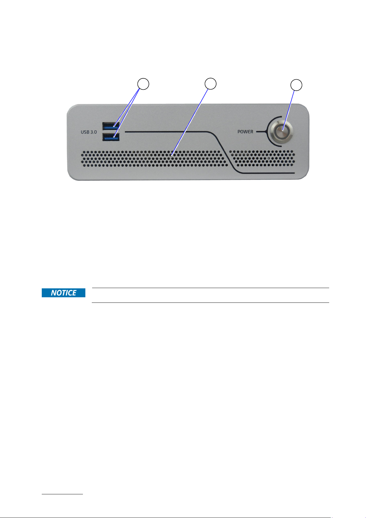
4.1. Front Side Features
The front side contains the power-on button, two USB 3.1 Gen 1 ports, and ventilation openings for air-output.
Figure 4: Front Side
12x USB 3.1 Gen 1 ports
2Ventilation openings (air-output)
3Power-on button with power LED
4.1.1. Front Connectors and Buttons
4.1.1.1. Power-On Button
The power-on button powers on/off the KBox B-201-CFL. The power-on button includes an integrated power LED
that lights up blue to indicate the powered on state. By pressing the power-on button for longer than four seconds
initiates a forced system shutdown, before switching off the power.
Performing a forced shut down can lead to loss of data or other undesirable effects!
4.1.1.2. USB 3.1 Gen 1
The two front panel USB 3.1 Gen 1 ports are backward compatible allowing for the connection of both USB 3.0 or
USB 2.0 compatible devices. Further USB ports are available on the rear panel, see Chapter 4.2: Rear Side.
For the USB 3.0 pin assignment, refer to Chapter 11.2: USB 3.1 Gen 1 Port & USB 3.1 Gen 2 Pin Assignment.
3
2
1

KBox B-201-CFL - User Guide, Rev 1.3
www.kontron.com // 20
4.2. Rear Side Features
The rear panel contains the main I/O interfaces, power-in connector (DC-IN), ventilation openings for air-output and
two top cover fastening screws.
The KBox B-201-CFL ‘Smart’ and ‘Value’ mainboard variants support different rear panel I/O interfaces, see Figure 5
and Figure 6.
Figure 5: Rear Panel KBox B-201-CFL (Smart)
1
PS/2 Keyboard
2PS/2 Mouse
34x USB 2.0
42x DP
5
Serial port
6DVI-D
72x LAN (GbE)
82x USB 3.1 Gen 2
92x USB 3.1 Gen 1
10 Audio line-in
11 Audio line-out
12 2x Top cover screws
13 Breakout for Wi-Fi antenna
14 DC-IN power connector
12 VDC (standard) or
24 VDC (optional variant)
15 Ventilation openings for
air-output
1
2
3
5
4
6
14
11
7
15
12
12
10
9
8
13
13
This manual suits for next models
1
Table of contents
Other S&T Desktop manuals

S&T
S&T kontron COMe-cVR6 User manual

S&T
S&T Kontron SBOX-5210 User manual

S&T
S&T Kontron KWS 3000-CML User manual

S&T
S&T Kontron SBOX-5002 User manual

S&T
S&T kontron KBox C-103-CFL Series User manual

S&T
S&T Kontron KBox B-201 User manual

S&T
S&T Kontron SBOX-7210 User manual

S&T
S&T Kontron KBox E-410-APL User manual


