Efinix Trion T20 Guide

AN 014: Using the Trion®
T20 Dual-Camera MIPI
Example Design
AN014-v2.0
May 2020
www.efinixinc.com
Copyright © 2020. All rights reserved. Efinix, the Efinix logo, Quantum, Trion, and Efinity are trademarks of Efinix, Inc. All other trademarks and
service marks are the property of their respective owners. All specifications subject to change without notice.

Contents
Introduction..................................................................................................................................... 3
Required Hardware......................................................................................................................... 4
Set Up the Hardware.......................................................................................................................5
Attach Daughter Cards, Jumpers, and Cables..................................................................................... 6
Connect Raspberry Pi Computers and Monitors..................................................................................7
Set Up the Raspberry Pi Cameras...........................................................................................................8
Program the Trion® T20 MIPI Development Board......................................................................... 9
Run the Example Design...............................................................................................................10
Use the Efinity Debugger to Control Video Output.......................................................................... 10
Next Steps................................................................................................................................................ 11
Shut Down the Example Design................................................................................................... 12
Revision History.............................................................................................................................12

AN 014: Using the Trion T20 Dual-Camera MIPI Example Design
Introduction
The Raspberry Pi MIPI CSI-2 dual-camera bridge example design illustrates how the Trion®
T20 FPGA can receive high-speed video data from multiple cameras, process it with a filter,
and then transmit the video over a high-speed interface to an application processor. The
demonstration uses the Trion® T20 MIPI Development Board, two Raspberry Pi v2 camera
modules, two Raspberry Pi computers, and two monitors.
Figure 1: T20 Dual-Camera CSI-2 Example Design Setup(1)
T20 FPGAs have two MIPI TX and two MIPI RX hardened interfaces. In this example,
each interface has two lanes, each of which runs at 1.5 Gbps. The Raspberry Pi cameras
connect to the T20 MIPI CSI-2 RX interfaces and send streaming video. The video passes
through the T20 FPGA to the MIPI CSI-2 TX interfaces, which send the video to Raspberry
Pi computers. The computers display the video on monitors.
Figure 2: T20 Dual-Camera MIPI CSI-2 Example Design Overview
Trion T20 MIPI
Development Board
Raspebrry Pi V2
Camera Module
RX0, 2 Lanes
I²C
Raspebrry Pi V2
Camera Module
RX1, 2 Lanes
I²C
TX0, 2 Lanes
I²C
Raspberry
Pi v4 Board
Raspberry Pi
Commands
Monitor
HDMI
TX1, 2 Lanes
I²C Raspberry
Pi v4 Board Raspberry Pi
Commands
Monitor
HDMI
Press pushbutton to switch
the camera inputs between
the monitors
When you press SW4, the T20 FPGA runs a Sobel filter that performs edge detection on the
video. Sobel filtering is a technique used to describe a large data set accurately with minimal
resources. When you press pushbutton SW5, the T20 FPGA switches the camera video feed
from one monitor to the other.
(1) This photo illustrates the design set up with Raspberry Pi 7" touch screen displays instead of monitors.
www.efinixinc.com 3

AN 014: Using the Trion T20 Dual-Camera MIPI Example Design
The example design also includes the Virtual I/O debugger core. With the Efinity® Debugger,
the Virtual I/O core lets you monitor changes in the design and adjust the red gain shown on
the monitors.
Figure 3: Dual-Camera MIPI CSI-2 Example Design Block Diagram
Trion T20 FPGA
Sobel
Filter
On/Off
Raspberry Pi
Computer v4
Sobel
Filter
On/Off
Raspberry Pi
Computer v4
RAW10
4-to-1 Line
Buffer
RAW10
4-to-1 Line
Buffer
Multiplexer
MIPI
CSI RX
MIPI
CSI RX
Raspberry
Pi Camera
Raspberry
Pi Camera
RGB
Gain
Virtual I/O
Debugger
SW5
SW4
The number of pixels the MIPI RX controller sends each clock cycle depends on the data
type. The example design uses the RAW10 data type, therefore, the MIPI RX controller
provides four 10-bit pixels each clock cycle. Because the Sobel filter only uses grayscale data,
the design converts the RAW10 data to YUV, uses the Y component for the filter, and then
converts back to RAW10. Finally, because the MIPI TX controller wants six 10-bit pixels
each clock cycle, the design packs the pixels by six before sending them to the controller.
Required Hardware
The design uses the following hardware:
•Trion® T20 MIPI Development Board
•4 Raspberry Pi Camera Connector Daughter Cards
•2 Raspberry Pi 4 boards
•2 Raspberry Pi V2 cameras
•4 15-pin flat cables
•2 HDMI cables, micro-HDMI to HDMI cable (or, HDMI to HDMI cable and micro-
HDMI to HDMI adapter)
•2 monitors with an HDMI input(2)
•2 USB type C cables
•3 micro-USB cables
•USB keyboard and mouse (one set is required; 2 sets are helpful)
•2 5-V power supplies
•4 jumper wires
•Laptop or personal computer with the Efinity® software installed
Tip: You may want to use Raspberry Pi kits that contain extra cables and hardware.
(2) You can use Raspberry Pi 7" touchscreen displays instead of monitors.
www.efinixinc.com 4

AN 014: Using the Trion T20 Dual-Camera MIPI Example Design
Set Up the Hardware
Setting up the hardware involves these general steps:
1. Attach the daughters cards, jumpers, and cables.
2. Connect the 2 Raspberry Pi boards and monitors.
3. Set up the 2 Raspberry Pi cameras.
After you set up the hardware, you program the design into the development board and then
run the example.
Note: The order in which you connect and power up the boards and Raspberry Pi computers is important
for the design to function correctly; essentially, the Raspberry Pi computers need to sync up with the
cameras before you turn on the development board.
Figure 4: Completed Hardware Setup
MIPI CSI RX
Channel 0
MIPI CSI TX
Channel 1
MIPI CSI RX
Channel 1
MIPI CSI TX
Channel 0
USB
Power
On/Off
VSUP1
Computer
LVDS TX LVDS RX
Raspberry Pi
v2 Camera
Raspberry Pi
v2 Camera
Raspberry Pi
Computer
Power
Raspberry Pi
Computer
Power
Monitor
Monitor
BGA169
Raspberry Pi
Camera Connector
Daughter Card
Trion T20 MIPI Development Board
T20
USB Keyboard
USB Mouse
Learn more: Refer to the T20 MIPI Development Kit User Guide for information on the components
available on the Trion® T20 MIPI Development Board.
www.efinixinc.com 5

AN 014: Using the Trion T20 Dual-Camera MIPI Example Design
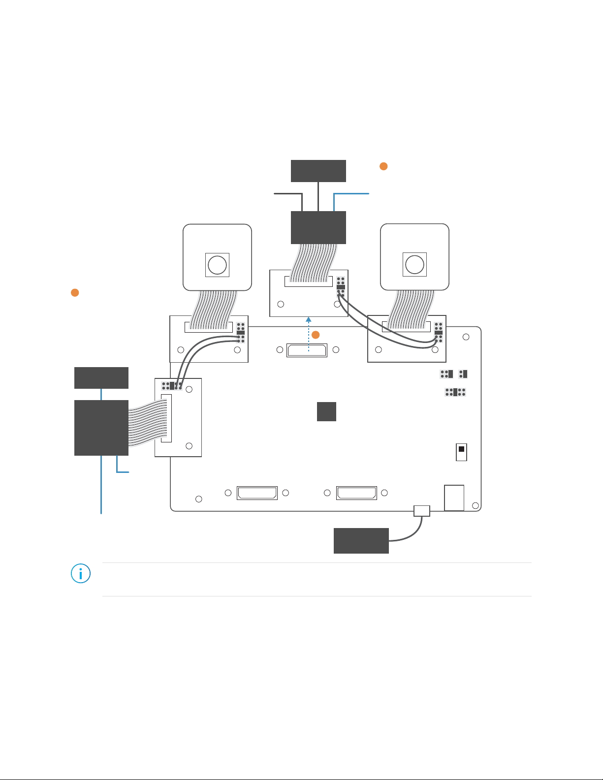
Attach Daughter Cards, Jumpers, and Cables
In this step you connect the 4 Raspberry Pi Camera Connector Daughter Cards to the Trion®
T20 MIPI Development Board and attach cables and jumpers. The following figure provides a
reference to help you make the correct connections.
Figure 5: Connecting Daughter Cards and Cables
MIPI CSI RX
Channel 0
MIPI CSI TX
Channel 1
MIPI CSI RX
Channel 1
MIPI CSI TX
Channel 0
BGA169
USB
Power
Jumper
Jumper
Jumper
Jumper
VSUP1
Jumper
Computer
LVDS TX LVDS RX
Raspberry Pi
Camera Connector
Daughter Card
Trion T20 MIPI Development Board
T20
Off
Important: Make sure that the Trion® T20 MIPI Development Board is turned off before connecting any
cards or cables.
1. If you have not already done so, attach standoffs to the Trion® T20 MIPI Development
Board and Raspberry Pi Camera Connector Daughter Cards.
2. On header VSUP1 (J2), connect pins 5 and 6 with a jumper. This connection sets voltage
power supply 1 to 3.3 V with power-up sequence. Leave the jumpers on J3 and J4 at the
defaults (connect pins 5 and 6 on J3 and pins 3 and 4 on J4).
3. Attach 4 Raspberry Pi Camera Connector Daughter Cards to the MIPI connectors.
4. On all 4 daughters cards, use a jumper to connect pins 5 and 6, which turns on the camera
enable.
5. Use jumper wires to connect pins on the daughter cards. These connections bridge the I2C
communication between the RX and TX.
Connect RX To TX
Channel 0 pin 2 Channel 0 pin 2
Channel 0 pin 4 Channel 0 pin 4
Channel 1 pin 2 Channel 1 pin 2
Channel 1 pin 4 Channel 1 pin 4
www.efinixinc.com 6

AN 014: Using the Trion T20 Dual-Camera MIPI Example Design
6. Connect a USB cable to the Trion® T20 MIPI Development Board and to your computer.
The board receives power through the USB cable.
Important: Leave the board turned off. You will turn it on later after you have set
up the Raspberry Pi cameras and computers.
Connect Raspberry Pi Computers and Monitors
In this step you connect the Raspberry Pi computers and the monitors. Do not connect the
power cables to the Raspberry Pi computers, you will do that in the next section.
Figure 6: Connect Raspberry Pi Computers and Monitors
MIPI CSI RX
Channel 0
MIPI CSI TX
Channel 1
MIPI CSI RX
Channel 1
MIPI CSI TX
Channel 0
USB
Power
Off
VSUP1
Computer
LVDS TX LVDS RX
Raspberry Pi
Computer
Monitor
BGA169
Trion T20 MIPI Development Board
T20
Raspberry Pi
Computer
Monitor
USB Keyboard
USB Mouse
1. Perform the following steps for the MIPI channel 1 TX:
a) Attach a 15-pin flat cable to the daughter card and to a Raspberry Pi computer.
b) Connect an HDMI cable to the Raspberry Pi computer's HDMI0 jack and to a
monitor.
c) Turn on the monitor.
2. Repeat step 1 for the MIPI channel 0 TX.
3. Connect a USB mouse and USB keyboard to the USB jacks on the channel 1 Raspberry Pi
computer.
Note: If you have a second USB keyboard and mouse, attach them to the channel
0 Raspberry Pi computer. If you only have 1 set, you will need to switch the
keyboard and mouse between the Raspberry Pi computers to enter commands and
control the video.
www.efinixinc.com 7
AN 014: Using the Trion T20 Dual-Camera MIPI Example Design
Set Up the Raspberry Pi Cameras
In this step you connect the cameras and enable them. After you connect the cameras, you
power the Raspberry Pi computers up one at a time and enable their connection to the
respective cameras.
Figure 7: Setting Up Cameras
MIPI CSI RX
Channel 0
MIPI CSI TX
Channel 1
MIPI CSI RX
Channel 1
MIPI CSI TX
Channel 0
USB
Power
Off
VSUP1
Computer
LVDS TX LVDS RX
Raspberry Pi
Computer
Monitor
BGA169
Trion T20 MIPI Development Board
T20
Raspberry Pi
Computer
Monitor
USB Keyboard
USB Mouse
Power
Raspberry Pi
v2 Camera
USB Keyboard
USB Mouse
Raspberry Pi
v2 Camera
Power
Set Up MIPI Channel 1
Raspberry Pi and Camera
1
Set Up MIPI Channel 0
Raspberry Pi and Camera
3
Detach
2
Note: These instructions assume that you have already set up your Raspberry Pi computer. If this is the
first time you are using them, follow the instructions on the Raspberry Pi web site to set up the board.
1. Connect the Raspberry Pi cameras to the MIPI RX channel 0 and 1 connectors.
2. Connect a power cable to the TX 1 Raspberry Pi computer. The Raspberry Pi boots to
the Raspbian desktop.
www.efinixinc.com 8

AN 014: Using the Trion T20 Dual-Camera MIPI Example Design
3. Enable the camera attached to MIPI channel 1:
Note: The Raspberry Pi camera is disabled by default.
a) Go to the Raspbian Desktop.
b) Choose Raspberry Pi > Preferences > Raspberry Pi Configuration.
c) Click the Interfaces tab.
d) Set the camera to Enable and click OK.
e) Reboot the Raspberry Pi.
4. Test the camera connection:
a) Open a command prompt.
b) Type the command vcgencmd get_camera and press return. The system should
respond supported=1 detected=1.
If the system does not detect the camera, check that you have set up the hardware
correctly.
5. Leaving all of the cables connected, detach the channel 1 TX daughter card from the
Trion® T20 MIPI Development Board.
Note: If you do not detach the daughter card, the system will experience a power
differential problem that will cause the second Raspberry Pi computer to not boot.
6. Remove the USB keyboard and mouse from the Raspberry Pi computer attached to TX
channel 1 and connect them to the computer attached to TX channel 0.
7. Connect a power cable to the TX 1 Raspberry Pi computer. The Raspberry Pi boots to
the Raspbian desktop.
8. Enable the camera attached to MIPI channel 0 as described in step 3.
9. Test the camera as described in step 4.
10. Re-attach the channel 1 TX daughter card to the Trion® T20 MIPI Development Board.
Program the Trion® T20 MIPI Development
Board
The Trion® T20 MIPI Development Board ships pre-loaded with a loopback design. To use
the dual-camera MIPI CSI-2 example design, you must program the design into the board.
Note: You can use active, passive, or JTAG programming.
1. Turn on the Trion® T20 MIPI Development Board.
2. Download the example design file, mipi_dual_camera_example_t20f169_devkit-
v<version>.zip, from the Support Center.
3. Unzip the file into your working directory.
4. Open the project (pi4_demo_top.xml) in the Efinity software and review it.
5. Use the Efinity® Programmer to download the bitstream file to your board. The example
includes a bitstream file, pi4_demo_top.hex.
Learn more: Instructions on how to use the Efinity® software is available in the Support Center.
www.efinixinc.com 9

AN 014: Using the Trion T20 Dual-Camera MIPI Example Design
Run the Example Design
With the hardware set up and the Trion® T20 MIPI Development Board programmed you
are ready to run the dual-camera video processing application.
1. Open a command prompt on the Raspbian Desktop.
Note: The USB keyboard and mouse should still be connected to the TX channel 1
Raspberry Pi computer.
2. Type the command to capture data:(3)
raspivid –t 0 –md 5 –fps 30 –p 300,20,480,270
raspivid captures video with a video encoding component.
-t 0 captures video until you stop it with a Ctrl+C command.
-md 5 captures video with 1640 x 922 resolution at 30 Hz
-p 300,20,480,270 superimposes the streamed video in a preview window
onto the Raspbian Desktop.
The monitor displays video from the camera.
3. Detach the USB keyboard and mouse from the TX channel 1 computer and connect them
to the TX channel 0 computer.
4. Repeat steps 1 and 2 to begin capturing video from the TX channel 0 camera.
5. Press SW5 to switch the feed from the RX channels. After 3 seconds, the channels switch
back automatically.
6. Press SW4 to toggle the Sobel filter on and off. The default is off.
7. Type Ctrl+C on the Raspberry Pi keyboard to stop streaming video on the TX channel 0
computer.
8. Detach the USB keyboard and mouse from the TX channel 0 computer and connect to
the TX channel 1 computer; type Ctrl+C to stop streaming.
9. Press SW2 to reset the system.
Important: Do not reset the system when the cameras are streaming video.
Use the Efinity Debugger to Control Video
Output
The example design includes a Virtual I/O debugger core, which you can use the control the
red, blue, and green gains in the video the design sends to the monitors.
1. Run the Efinity software.
2. Open the Debugger. The tool opens to the Debug perspective. The VIO_0 debug core
sources and probes displays.
3. Click Connect Debugger. The probes show the values on the MIPI signals.
4. Set the PROBE_TRIGGER signal to 1 (0 is the default).
(3) Refer to the Raspberry Pi web site for a complete listing of camera commands.
www.efinixinc.com 10

AN 014: Using the Trion T20 Dual-Camera MIPI Example Design
5. To adjust the red, green, or blue gain, enter a value from 0 to 7 in the Value field for
the red_gain, green_gain and blue_gain sources. 0 is the minimum setting and 7 is the
maximum setting. The default is 4.
Additionally, the Virtual I/O debugging signals are routed to the J12 header on the Trion®
T20 MIPI Development Board. You can use this header to monitor the MIPI HSYNC and
VSYNC signals directly.
Next Steps
Once you have demonstrated the functionality of the example design, you can use it to
explore how the T20 MIPI CSI-2 interface works.
•The TX PHY speed is 1.5 Gbps to demonstrate the hardened PHY capability. You can
use the Efinity Interface Designer to change the setting to any speed from 1 to 1.5 Gbps.
Note: Do not change the lane mapping in the Interface Designer because it is
mapped for the example design's hardware.
•The Interface Designer contains settings for the TX and RX interface timing. The design
uses specific timing settings that work with the hardware (Raspberry Pi camera and
computer). If you want to explore the effect these timing settings have on the interface
functionality, use the MIPI Utility and AN 015: Designing with the Trion MIPI
Interface to guide your timing choices.
•Clocking is an important part of building a MIPI CSI-2 design. The MIPI RX uses a
100 MHz clock, mipi_cal_clk. The RTL design uses the clock mipi_pclk. The
example design does not have a frame buffer, therefore, it needs to process the data
from the RX line buffer faster than the input data rate. You can adjust the speed of
mipi_pclk, but it should be faster than 107 MHz to keep up with the RX controller.
www.efinixinc.com 11

AN 014: Using the Trion T20 Dual-Camera MIPI Example Design
Shut Down the Example Design
Wihen you are finished using the example design, use these steps to shut it down.
1. Type Ctrl+C on the Raspberry Pi keyboard to stop streaming video on the attached
camera.
2. Detach the USB keyboard and mouse from the Raspberry Pi computer and connect them
to the other computer.
3. Type Ctrl+C to stop streaming video on the camera.
4. Press SW2 to reset the system.
Important: Do not reset the system when the cameras are streaming video.
5. Turn off the Trion® T20 MIPI Development Board.
6. Remove power from the Raspberry Pi computers.
7. Remove all cables.
Revision History
Table 1: Revision History
Date Version Description
May 2020 2.0 Clarified instructions for setting up the cameras.
January 2020 1.0 Initial release.
www.efinixinc.com 12
Table of contents


