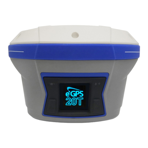
eGPS Solutions 20TL User manual

eGPS 20TL GNSS Receiver
Quick Start Guide

Copyright
Copyright 2021 eGPS Solutions, Inc. | All rights reserved.
Trademarks
All product and brand names mentioned in this publication
are trademarks of their respective holders.
Safety Warnings
The Global Positioning System (GPS) is operated by the
U.S. Government, which is solely responsible for the
accuracy and maintenance of the GPS network. Accuracy
can also be affected by poor satellite geometry and
obstructions, like buildings and heavy canopies.
FCC Interference Statement
This equipment has been designed to comply with the
limits for a Class B digital device, pursuant to part 15 of the
FCC Rules in Portable Mode. These limits are designed to
provide reasonable protection against harmful interference
in a residential installation.
Operation is subject to the following two conditions:
(1) this device may not cause harmful interference and
(2) this device must accept any interference received,
including interference that may cause undesired operation.
1

Table of Contents
1. Introduction
1.1. Safety Information
1.1.1. Warnings and Cautions........................
1.1.2. Regulations and Safety........................
1.1.3. Use and Care.......................................
1.2. Technical Support..............................................
1.3. Disclaimer..........................................................
1.4. Your Comments.................................................
2. Getting Started with the eGPS 20TL
2.1. About the Receiver............................................
2.2. Parts of the Receiver
2.2.1. Front Panel...........................................
2.2.2. Lower Housing.....................................
2.2.3. Receiver Ports......................................
2.3. Batteries and Power
2.3.1. Internal Batteries
2.3.1.1. Charging the Batteries..........
2.3.1.2. Battery Safety........................
2.3.2. External Power Supply........................
2.4. Inserting Batteries and SIM Card......................
2.5. Product with Accessories..................................
2.6. Connecting to an Office Computer...................
2.7. X-PAD Project Setup.........................................
2.8. X-PAD Network Rover.......................................
2.9. X-PAD Radio Base.............................................
2.10. X-PAD Radio Rover..........................................
2.11. X-PAD Static....................................................
4
4
5
5
5
6
6
7
10
10
12
13
14
15
16
17
18
28
36
42
48
2

3. Communication Ports Definition
3.1. eGPS 20TL Receiver I/O Port (7-Pin Lemo
Port) Definition..................................................
4. Contact Information.....................................................
5. Warranty Terms.............................................................
6. 20TL Specifications.......................................................
54
55
55
56
3

1. Introduction
The eGPS 20TL GNSS Receiver Quick Start Guide describes
how to set up and use the eGPS 20TL GNSS receiver.
“The receiver” refers to the eGPS 20TL GNSS receiver
unless otherwise stated.
Even if you have used other Global Navigation Satellite
Systems (GNSS) products before, eGPS Solutions
recommends that you spend some time reading this manual
to learn about the special features of this product.
1.1. Safety Information
1.1.1. Warnings and Cautions
An absence of specific alerts does not mean that there are
no safety risks involved.
Warning or Caution information is intended to minimize the
risk of personal injury and/or damage to the equipment.
WARNING - A Warning alerts you to a potential
misuse or wrong setting of the equipment.
CAUTION - A Caution alerts you to a possible risk of
serious injury to your person and/or damage to the
equipment.
1.1.2. Regulations and Safety
The receivers contain a built-in wireless modem for signal
communication through Bluetooth®wireless technology or
through an external communication datalink. Regulations
regarding the use of the wireless modem vary greatly from
country to country. In some countries, the unit can be used
4

without obtaining an end-user license. However, in some
countries, administrative permissions are required. For
license information, consult your local dealer. Bluetooth®
operates in license-free bands.
Before operating an eGPS 20TL GNSS receiver,
determine if authorization or a license to operate the unit is
required in your country. It is the responsibility of the
end-user to obtain an operator’s permit or license for the
receiver for the location or country of use.
1.1.3. Use and Care
This receiver is ruggedized to withstand tough
environmental conditions that occur in the field. However,
the receiver is a high-precision electronic instrument and
should be treated with reasonable care.
CAUTION - Operating or storing the receiver
outside the specified temperature range will cause
irreversible damage.
1.2. Technical Support
If you have a problem and cannot find the information you
need in this manual or on the eGPS Solutions website
www.egps.net, you can contact our technical support team
at (770) 695-3361.
1.3. Disclaimer
Before using the receiver, please make sure that you have
read and understood this Quick Start Guide, as well as the
safety information. eGPS Solutions holds no responsibility
for the incorrect operation by users and for the losses
incurred by misunderstanding this guide. However, eGPS
Solutions reserves the right to update and optimize the
5

contents in this guide regularly. Please contact your local
dealer from which you purchased the receiver for new
information.
1.4. Your Comments
Your feedback about this user guide will help us to improve
it in the future. Please email your comments to
2. Getting Started with the eGPS 20TL
2.1. About the Receiver
The eGPS 20TL GNSS receiver incorporates a GNSS engine,
GNSS antenna, internal radio, 4G cellular modem,
Bluetooth, WiFi and dual batteries in a ruggedized and min-
iature unit. Either unit may be a base, rover, or used without
other devices for static collection.
The LCD panel enables users to check satellite-tracking
status, internal battery status, WiFi status, working mode,
data logging status and basic receiver information.
The receiver can be used as part of a Network RTK GNSS
system with Carlson SurvCE, MicroSurvey Field Genius or
CHC LandStar7 Android software. Static positions can be
stored in Rinex 2.11 format for easy OPUS submittal using
only the receiver.
When using the eGPS 20TL without additional equipment,
configuration of the many features is accomplished through
a web browser. CHC LandStar7 may also be downloaded
from the Android app store. Static positions can be taken
by pressing the function button for 5 seconds.
6

2.2. Parts of the Receiver
The operating controls are all located on the front panel.
Battery compartment and SIM card slot are located on the
back. Serial ports and connectors are located on the
bottom of the unit.
2.2.1. Front Panel
The following figure shows a front view of the receiver.
Front Panel
Correction LEDSatellite LED
Power ButtonFunction Button
7
The front panel contains four indicator LEDs and two
buttons.

Indicator
LED/ Button
Color Description
Correction
LED
Green • Indicated whether the receiver
is transmitting/receiving
differential data.
• The green LED flashes once
per second when:
a) As a Base Station:
successfully transmitting
differential data.
b) As a Rover Station:
successfully receiving
differential data from Base
Station.
Satellite LED Blue • Shows the number of satellites
that the receiver has tracked.
• When the receiver is searching
satellites, the blue LED flashes
once every 5 seconds.
• When the receiver has tracked
N satellites, the blue LED will
flash N times every 5 seconds.
8
NOTE - The screen display comes up and notifies
“Battery Low” when batteries need to be recharged.

9
Name Color Description
Function
Button
Yellow • Move to the next line of the menus
or options.
• Move to next character of the value
that you want to change.
• Cancel the change you make on a
function.
Power
Button
Red Works as a Power button:
Press and hold this button for 3
seconds to turn on or turn off the
receiver.
Works as a Confirm button.
Power Button
Power Button
Function Button
Function Button
FN
To Reset
To reset receiver use FN to turn on display, press FN 5
more times until you reach the Set icon, push Power
button, then FN 6 times until you reach OEM board
Reset then push Power button. Will ask "Reset OEM
Board? Use FN for OK, will see message "Reset
success, will reboot"

2.2.2. Lower Housing
The lower housing contains one SIM card slot, two battery
compartments, one TNC radio antenna connector, two
communication and power ports, one 5/8-11 threaded
insert, and two nameplates.
10

Port Name Description
I/O Port This port is a 7-pin LEMO
connector that supports RS-232
communications and external
power input.
Users can use the HCE320
Type-C Cable supplied with the
system to realize RS-232
communications between
the receiver and computer or
controller. Also, users can use a
7-pin cable to transmit
differential data to an external
radio.
USB Port This port is a mini-USB
connector that supports USB
communications.
Users can use the USB Cable
supplied with the system to
download the logged data to a
computer.
Radio
Antenna
Connector
Connect the UHF radio
antenna to the internal radio
of the receiver. This connector
is not used if you are using an
external radio.
11
2.2.3. Receiver Ports

2.3. Batteries and Power
2.3.1. Internal Batteries
The receiver comes with two rechargeable lithium-ion
batteries.
2.3.1.1. Charging the Batteries
The rechargeable lithium-ion batteries are supplied
partially charged. Charge the batteries completely before
using for the first time. To charge the batteries, place them
in the supplied charger and wait until the green light at
each battery stops flashing and remains solid green.
WARNING - Charge and use the rechargeable
lithium-ion batteries only in strict accordance with
the instructions. Charging or using the batteries in
unauthorized equipment can cause an explosion or
fire and can result in personal injury and/or
equipment damage.
To prevent injury or damage:
• Do not charge or use the battery if it appears to be
damaged or leaking.
• Charge the lithium-ion battery only in an eGPS 20TL
charger that is specified to charge it. Be sure to
follow all instructions that are provided with the
battery charger.
• Discontinue charging a battery that gives off extreme
heat or a burning odor.
• Use the battery only in eGPS 20TL equipment.
• Use the battery only for its intended use and
according to the instructions in the product
documentation.
12

2.3.1.2. Battery Safety
WARNING - Do not damage the rechargeable
lithium-ion batteries. A damaged battery can cause
an explosion or fire and can result in personal
injury and/or property damage.
To prevent injury or damage:
• Do not use or charge the battery if it appears to be
damaged. Signs of damage include but are not
limited to discoloration, warping and leakage of
battery fluid.
• Do not expose the battery to fire, high temperature
or direct sunlight.
• Do not immerse the battery in water.
• Do not use or store the battery inside a vehicle
during hot weather.
• Do not drop or puncture the battery.
• Do not open the battery or short-circuit its contacts.
WARNING - Avoid contact with the rechargeable
lithium-ion battery if it appears to be leaking.
Battery fluid is corrosive and contact with it can result
in personal injury and/or property damage.
To prevent injury or damage:
• If the battery leaks, avoid the battery fluid.
• If battery fluid gets into your eyes, immediately rinse
your eyes with clean water and seek medical
attention. Please do not rub your eyes!
• If battery fluid gets onto your skin or clothing,
immediately use clean water to wash off the battery
fluid.
13

2.3.2. External Power Supply
Two methods are available for providing external power to
the receiver. Use the included GPS to USB PC Data Cable
with Power Adapter and either the wall charging adapter or
the optional 12 volt battery cable.
In the office:
The Power Adapter is connected with AC power of
100 - 240 V and the output port of the Power Adapter
connects to the Power Port of the GPS to USB PC Data
Cable.
In the field:
The external power cable is connected with a vehicle
battery, and the output port of the external power cable
connects with the Power Port of the GPS to USB PC Data
Cable.
WARNING - Use caution when connecting external
power cable’s clip leads to a vehicle battery. Do not
allow any metal object to connect (short) the
battery’s positive(+) terminal to either the negative(-)
terminal or the metal part of the vehicle battery. This
could result in high current, arcing, and high
temperatures, exposing the user to possible injury.
14

15
2.4. Inserting Battery and SIM Card
Push down on the button on the battery cover to open the
cover.
Align the connectors of the batteries with the connections
on the receiver. Insert the battery into the battery
compartment until it is locked by the battery bail. Snap the
battery cover back into place when finished.
To remove the batteries, push down on the button on the
battery cover and open the cover. Slide the battery bail to
the left or right.
Push down
on button
and lift
Battery cover Battery
compartment
SIM card
slot
The SIM card can be inserted in the slot above the battery
compartments. The notched end of the SIM card does NOT
go into the slot.
To remove the SIM card, lightly press down on the card, and
pop the card out of the socket.
Tip – The SIM card is provided by your GSM cellular
network service provider.
Battery bail

16
2.5. Product with Accessories
Item Picture
eGPS 20TL GNSS Receiver
UHF Bar Antenna (450-470
MHz)
P/N: 2004 020 011
HCE320 USB Type-C
Lithium Batteries
P/N: 2004 050 017
Battery Charger
P/N: 2004 050 030 C300
Auxiliary H.I. Tool
Rover Hard Case
P/N: 2004 060 005
Optional Base Hard Case
P/N: 2004 060 004

17
2.6. Connecting to an Office Computer
The receiver can be connected to an office computer for
serial data transfer or settings via a HCE320 USB Type-C.
Before you connect to the office computer, ensure that the
receiver is powered on by the internal battery or external
power.
The following figure shows how to connect to the computer
for data transfer:
HCE320 USB Type-C

2.7. X-PAD Project Setup
1. To start a project, go to
the ‘Job’ tab, and select
‘New/Open Job’.
2. Clicking on the icon
indicated allows you to
choose your job interface
style (Gallery, List, Map, or
Calendar).
Explore these options, and
select the one that best suits
your approach.
Click ‘New Job’ to open the
job creation dialogue.
18

3. Give your project a name.
The other settings are
explored in more depth
elsewhere.
Hit ‘Accept’.
4. Select ‘Coord’ to review
coordinate system selection.
You will notice it is greyed
out. We will see how to
change the system later.
19
Table of contents
Other eGPS Solutions Receiver manuals
Popular Receiver manuals by other brands
Denon Professional
Denon Professional DN-200AZB user guide
Entone
Entone Kamai 6 quick start guide

Flying Industry Development
Flying Industry Development 0020535 quick guide

Inter-m
Inter-m IPA-R10 Operation manual
Sangean
Sangean ATS-909X - WORLD BAND RADIOS manual
WILDLIFE
WILDLIFE TRX-10S quick start guide
