EGS Pentax G6N User manual
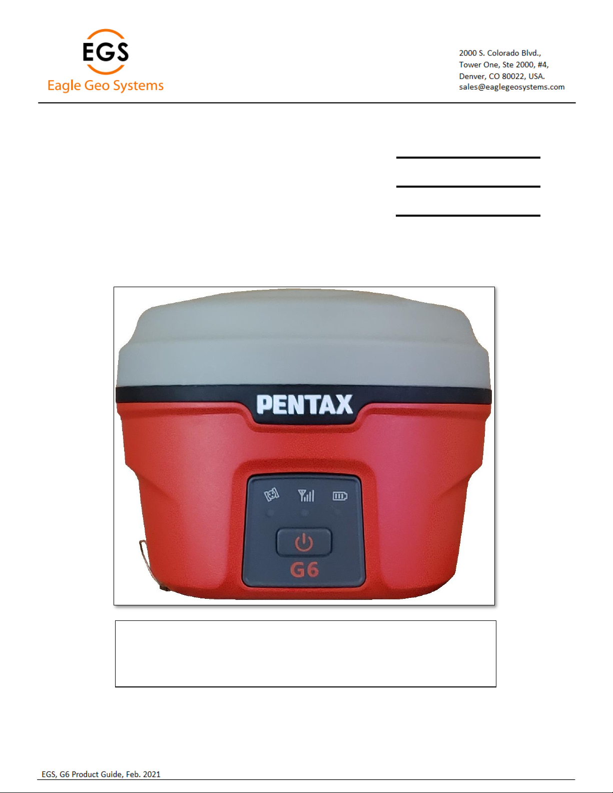
Pentax G6N
Product Guide
Version 2.04
Revision Version 2.00, September 2020
Version 2.02, November 2020
Version 2.03, December 2020
Version 2.04, February 2021

Page | 2
Table of Contents
1Product Information ..........................................................................................................................................................................3
1.1 G6N Front Panel ..........................................................................................................................................................................3
1.2 G6N Battery Compartment..........................................................................................................................................................3
1.3 G6N Ports & Speaker...................................................................................................................................................................4
2G6 Basic Operation ............................................................................................................................................................................5
2.1 Power Button...............................................................................................................................................................................5
2.2 G6N Panel LEDs............................................................................................................................................................................5
2.3 Battery Compartment Door.........................................................................................................................................................6
2.4 Nano SIM Card.............................................................................................................................................................................6
2.5 Micro SD Card..............................................................................................................................................................................6
2.6 Installing a Battery.......................................................................................................................................................................7
2.7 Wired/Cable Connections............................................................................................................................................................7
2.8 G6N ARP ......................................................................................................................................................................................8
2.9 Antenna Height............................................................................................................................................................................8
2.10 Bluetooth ID.................................................................................................................................................................................9
3Web UI .............................................................................................................................................................................................10
3.1 Status.........................................................................................................................................................................................11
3.2 Information................................................................................................................................................................................11
3.3 Satellites ....................................................................................................................................................................................12
3.4 Download ..................................................................................................................................................................................13
3.5 Management .............................................................................................................................................................................14
3.6 Settings......................................................................................................................................................................................15
3.6.1 Working Mode ...................................................................................................................................................................15
3.6.2 Device configuration ..........................................................................................................................................................18
3.6.3 NMEA Message..................................................................................................................................................................19
3.6.4 Relay Mode ........................................................................................................................................................................20
4G6 standard accessories ..................................................................................................................................................................22
4.1 Shipping Case.............................................................................................................................................................................22
4.2 Power.........................................................................................................................................................................................22
4.3 Battery Pack...............................................................................................................................................................................22
4.4 Battery Charger .........................................................................................................................................................................22
4.5 UHF antenna..............................................................................................................................................................................23
4.6 Accessories ................................................................................................................................................................................23
5Appendix 1 Default radio configuration...........................................................................................................................................24
6Appendix 2: Voice Messages............................................................................................................................................................25
7Appendix 3 G6N Specifications ........................................................................................................................................................26
Page | 3
1Product Information
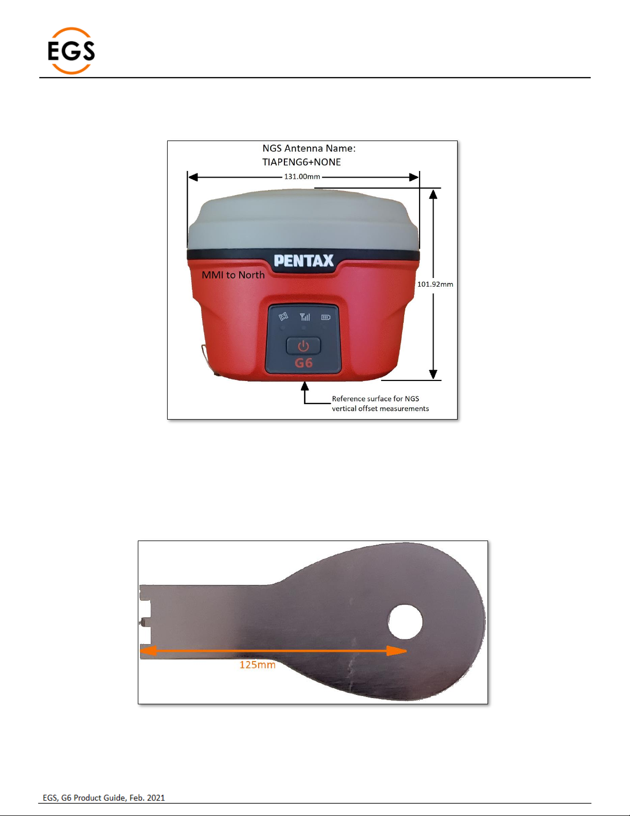
1.1 G6N Front Panel
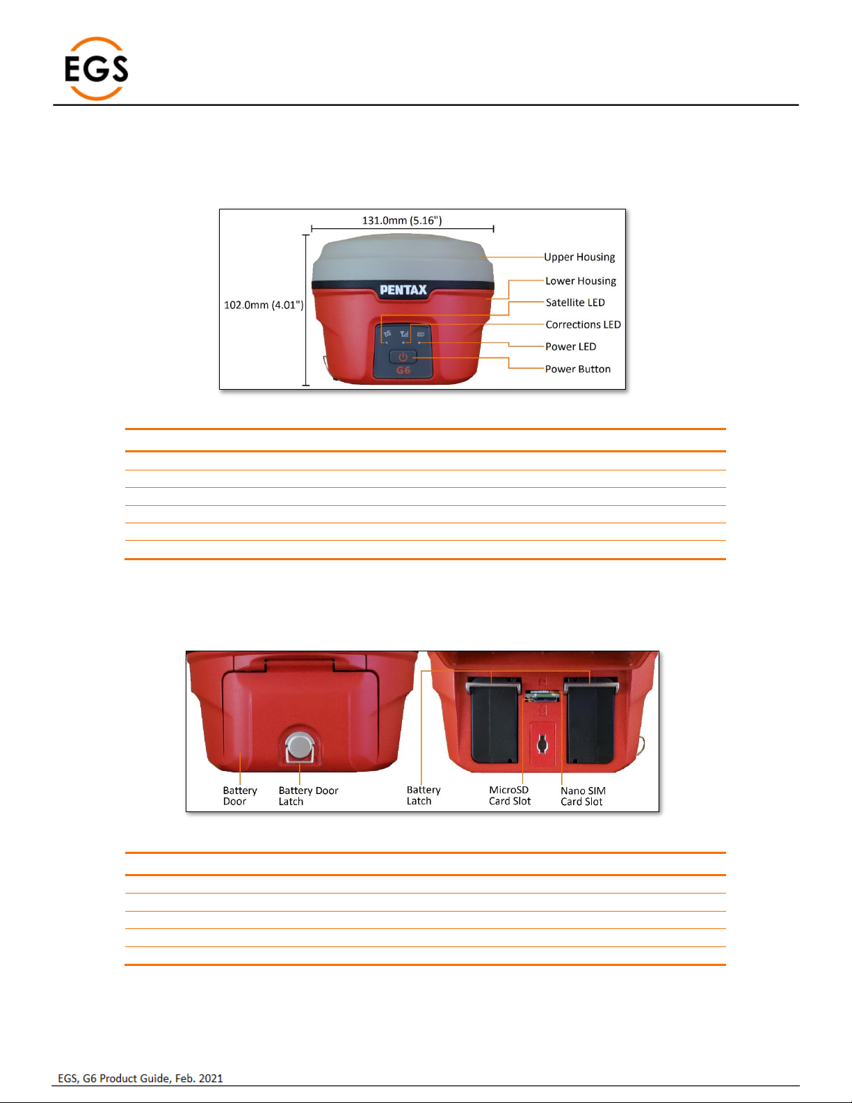
The front of the G6N has an information panel with 1 power button and 3 LED indicators.
Figure 1: G6N Measurements and Front Panel
Item
Function
Upper Housing
Cover for GNSS antenna
Lower Housing
Access for batteries, ports, status panel
Satellite LED
Blinks for number of satellites tracked
Corrections LED
Blinks for corrections received
Power LED
Solid green for > 10% battery, Red for < 10%
Power Button
Turns instrument On/Off
1.2 G6N Battery Compartment
The back side has two battery compartments along with two slots above, one for SIM card another for Micro SD card.
Figure 2: G6N - Back and Battery Compartment
Item
Function
Door, Battery Compartment
Access to battery compartment
Latch, Battery Door
Lock / Unlock battery compartment
MicroSD Card Slot
Insert or Remove microSD card
Nano SIM Card Slot
Insert or Remove Nano SIM card
Battery Door Latch
Lock / Unlock battery

Page | 4
1.3 G6N Ports & Speaker
The ports and speaker are located on the bottom side of the instrument. In addition, the instrument serial number and certification
labels are also on the bottom side of the instrument.
Figure 3: G6N Bottom
Description
Function
Speaker
Audio announcements
5-pin Lemo
External Power & external radio
7-pin Lemo
USB port
TNC female
UHF antenna
Page | 5
2G6 Basic Operation
This section highlights the basic operations of G6.
2.1 Power Button
The main function of power key is for power on/off and to confirm a selection.
Function
Button Press
Comments
Power On
Press for 2 s then release
LEDs come on & system boots up, position
status announcement
Power Off
Press for 3 s to blink LEDs, release, press
once and release
All LEDs blink after 3s press, power off
announcement, press once and release to
confirm
Self-Check
Press for 3 s, release, press for 3 s, release
Self-check announcement after second
button press. Announcement for each
module self-check pass/fail.
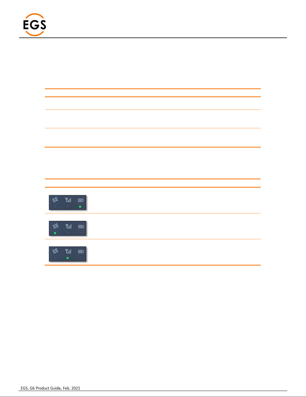
2.2 G6N Panel LEDs
The G6N has 3 LED Indicators for Power, Corrections and Satellite tracking.
LED
Status
Function
Power LED
Solid Green = > 10%
Red = < 10%
Indicates battery capacity
When <10%, 3 beeps every 60 s
~30 minutes operation when LED is Red
Satellite LED
Green = Tracking
Satellites
Blinks to indicate number of satellites
30 s cycle
LED is Off for zero satellites
Corrections LED
Green & Blinking
Blinks to indicate receive/transmit
corrections

Page | 6
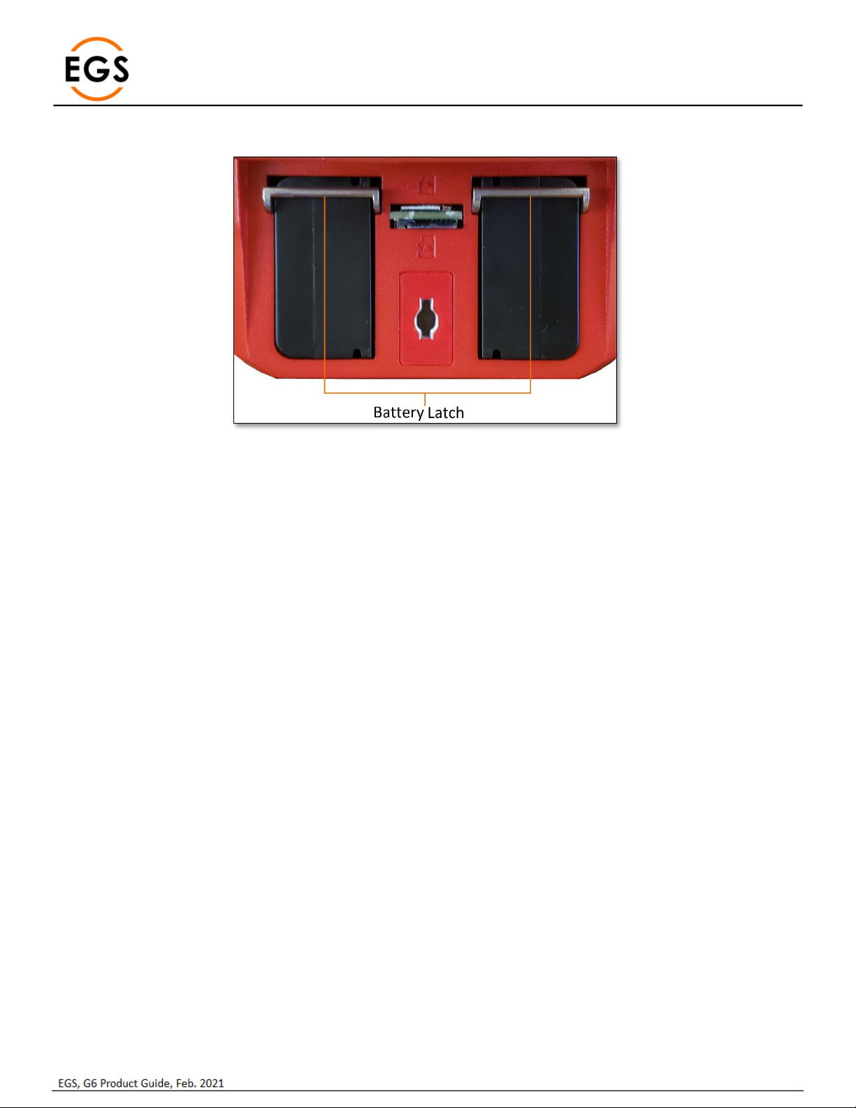
2.3 Battery Compartment Door
The battery compartment latch has a drawing guide indicating the locked and unlocked latch position. The handle is horizontal when
locked, and vertical when unlocked.
Figure 4: Battery Door Latch
2.4 Nano SIM Card
Ensure the instrument is powered Off. The Nano SIM card slot is accessed by opening the battery compartment door.
Insert the Nano SIM card into the upper slot, as shown in the guide above the slot, noting the angled edge.
To install the Nano SIM card, just push the SIM card into the SIM card slot. To eject the Nano SIM card, push the card in to release.
Figure 5: SIM Card (Top) and SD Card (Bottom)
A valid SIM card must be installed before using the integrated cellular modem in the G6.
2.5 Micro SD Card
Ensure the instrument is powered Off. The microSD card slot is accessed by opening the battery compartment door. This is the lower
slot between the two batteries. To install the Micro SD card, push the card into the card slot as shown in the guide below the slot. To
eject the Micro SD card, push the card in to release.
Page | 7
2.6 Installing a Battery
Figure 6: Battery Latch
To install the battery, turn open the battery compartment latch, and the battery compartment door will open upwards.
Insert the battery into the battery compartment, the battery latch will lock the battery in place.
Close the battery compartment door and lock the battery door latch.
To remove the battery, open the compartment latch, open the battery door and push the battery latch up to release the battery.
2.7 Wired/Cable Connections
The bottom of the receiver has 3 ports:
•TNC female port for the UHF radio antenna
•5-pin Lemo for external power & external interface
•7-pin Lemo for RS232/USB interface.
Page | 8
2.8 G6N ARP
The Antenna Reference Point (ARP) is at the bottom of the G6N. The Antenna Code is TIAPENG6.
Figure 7: G6 Dimensions
2.9 Antenna Height
When using the G6N as a Rover, the antenna height is the vertical height of the survey pole. This is direct to the ARP, so no offsets are
required for a vertical survey pole.
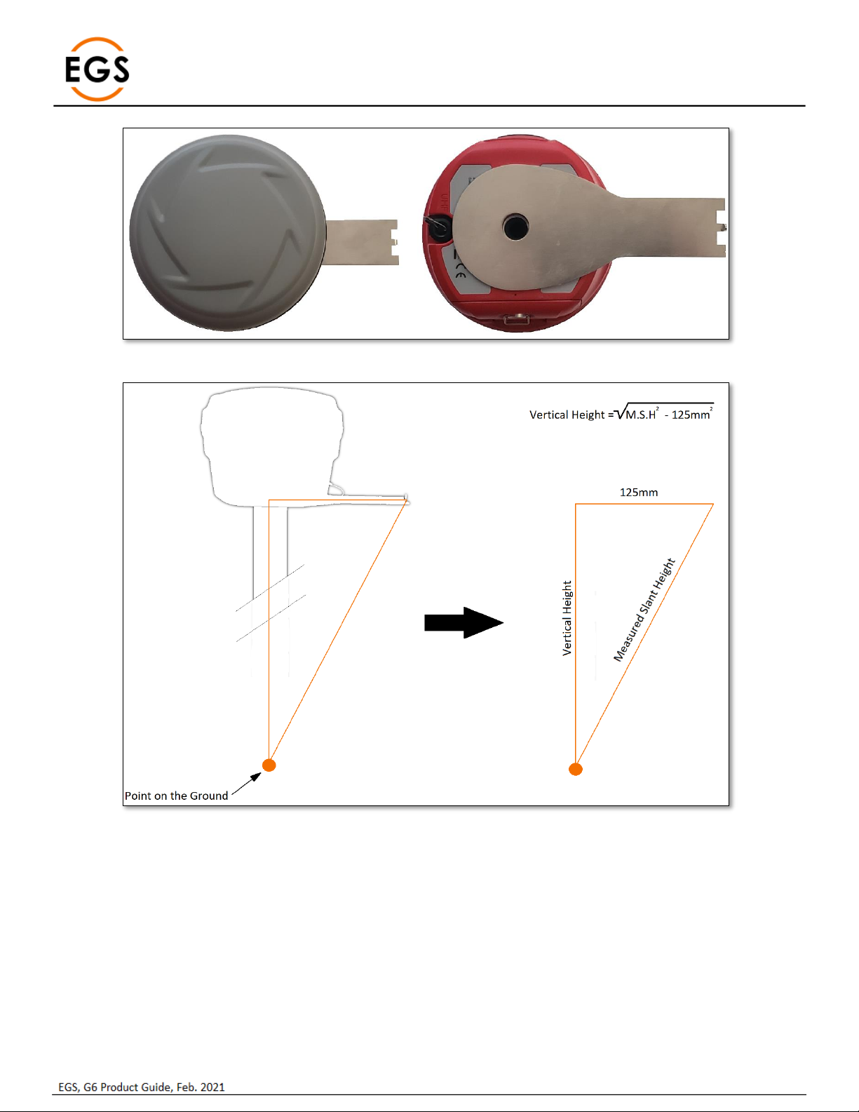
For a Slant Height, a Slant Height Adapter is supplied to allow a convenient measurement around a tripod or tribrach.
Figure 8: Slant Height Adapter
Page | 9
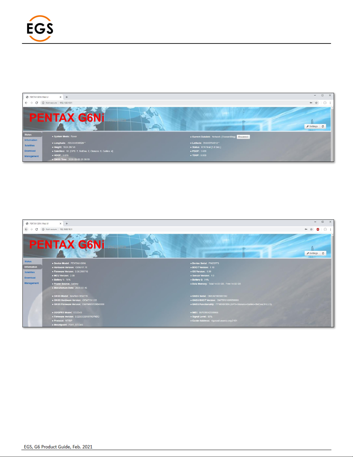
Figure 9: Slant Height Adapter Mounting Location
Figure 10: Slant Height Measurement
When measuring Slant Height from the ground to the end of the Slant Height Adapter, the Vertical Height can be calculated as shown
in the figure above.
2.10 Bluetooth ID
Bluetooth communication is typical for data collection. The Bluetooth ID is the serial number of the G6N. The Bluetooth PIN is 1111.

Page | 10
3Web UI
The G6 has an on-board Web UI that is accessed via Wi-Fi. A smart phone, tablet, data controller, PC and similar devices with a web
browser can be used to connect the G6 via WI-FI. The G6 WI-FI does not have the Internet access, so only the Web UI pages are
viewable.
Figure 11: G6N SSID
After connecting the G6’s WI-FI denoted by the Serial Number, open a web browser and input IP ‘192.168.10.1’to access the on-board
Web UI.
The default login details are:
•IP Address: 192.168.10.1
•Account: admin
•Password: password
Figure 12: G6 Default Web UI Login Details
The browser will then display the Pentax Web UI, starting on the Status page (Figure 8) with the Serial Number of the G6 shown in the
web page header. The Web UI has a menu on the left side with categories for:
•Status
•Information
•Download
•Management
A Settings button is displayed on the upper right for user settings input.
Page | 11
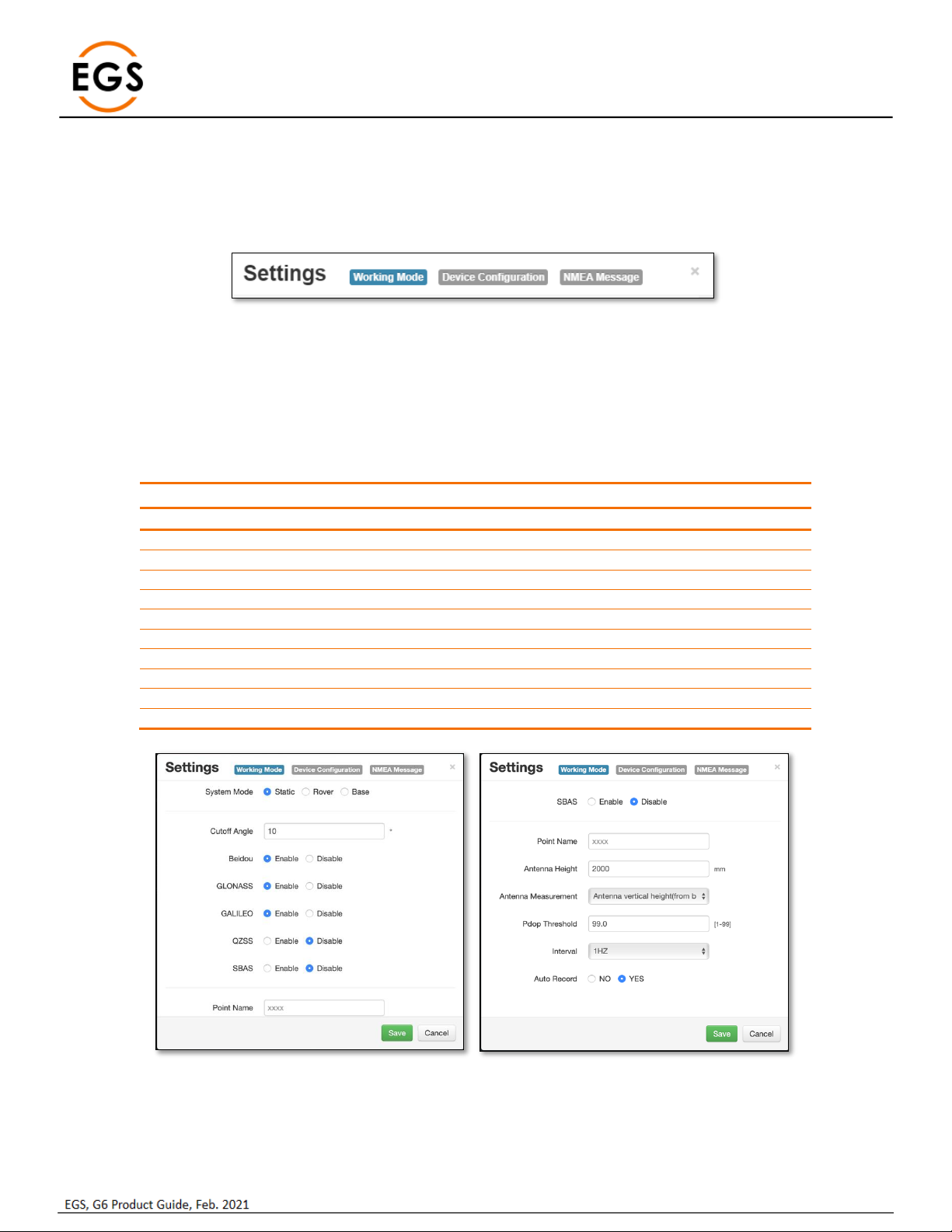
3.1 Status
The Status webpage displays a summary of the current GNSS positioning for a fast confirmation.
The webpage displays the System Mode, GNSS position, Position Mode & Latency, Satellites used, DOPs, GNSS Time and the Current
Datalink used for differential corrections. There is a button to quickly Disconnect/Connect the datalink.
Figure 13: G6 Web UI –Status
3.2 Information
The Information webpage displays details about the main OEM modules in the G6N, such as hardware& firmware versions, sensor
firmware version, power status, Memory, GNSS model & firmware version, cellular modem details, NTRIP connection, and power
status.
Figure 14: Web UI –Information

Page | 12
3.3 Satellites
The Satellites webpage displays the tracked satellites and allows setting the Cutoff Angle (elevation mask) to limit tracking to satellites
below this angle. There is a display choice of display between a Table and a Skyplot.
Figure 15: WebUI –Satellites - Table

Page | 13
Figure 16: WebUI - Satellites - Skyplot
3.4 Download
The Download webpage displays the raw data files recorded on the G6, with buttons to Download, Delete or Convert a file.
The files may be downloaded individually by using the Download button or combined using the Package button when multiple files
are selected.
The raw data files may be deleted individually using the Delete button, or multiple files after selecting and using the Delete Selected
button. A raw data file may be converted to RINEX by using the Convert button.
Figure 17: Web UI –Download

Page | 14
3.5 Management
The Management webpage allows the user to Install New Firmware, Register the G6N, Register the GNSS, set/change Password, view
logs, Format the SD card, Self-Test, Restore Factory Settings, and Reset the receiver.
Figure 18: Web UI –Management
Option
Description
Install New Firmware
Select the Choose File button, select the Pentax firmware file, then click
the Upload File button.
Registration
Pentax Registration is factory loaded on the G6N. This is a set of
permissions for the unit to operate properly. Further permissions are
generally unnecessary.
GNSS Registration
The GNSS Registration is factory loaded on the G6N. This is the set of
permissions of the internal GNSS board. Further permissions are
generally unnecessary.
Security
Option to modify the default password for login to the G6N WebUI.
View Logs
Option to view and download the internal G6N log files. The APP log
records information on the applications running on the G6N. The OS
log records information relating to the operating system of the G6N.
Format Internal Disk
Option to format the internal SD card. This option erases all data and
reformats the SD card.
Self-Test
Option to run an on-board self-test on key modules of the G6N
Restore Factory Settings
Option to reset the G6N to factory default settings.
Reset
Option for a Hard Reset of the G6N. The G6N will power down and
power back on again after a Reset. The Wi-Fi connection has to be re-
established after a Reset.
Page | 15
3.6 Settings
The Settings sections allows for user configuration of the G6N. This is presented in three sections by tabs:
•Working Mode
•Device Configuration
•NMEA Message
Each section is further discussed below.
3.6.1 Working Mode
This Working Mode menu allows the user to select a System Mode as a Base, Rover, or Static. Each mode is unique and different
settings will be displayed for user selection and input.
3.6.1.1 Static Mode
Static mode allows for the G6N to be configured for a static session, typically for post-processing purposes. When this option is
selected, the webpage allows the user to make the settings shown in the following table.
Option
Description
Cutoff Angle
Sets a minimum elevation angle for using satellites
BeiDou
Enable / Disable the BeiDou Constellation
GLONASS
Enable / Disable the GLONASS Constellation
Galileo
Enable / Disable the Galileo Constellation
QZSS
Enable / Disable the QZSS Constellation
SBAS
Enable / Disable the SBAS Constellation
Point Name
Specify a 4-digit Point Name
Antenna Height
Set the Antenna Height
PDOP Threshold
Set a PDOP threshold for logging data
Logging Interval
Set the logging interval from 60s, 30s, 15s, 5s, 2s, 1Hz, 2Hz, 5Hz
Auto Record
Set this option to automatically log raw data upon startup
Figure 19: Static Mode settings

Page | 16
3.6.1.2 Rover Mode
When the System Mode is Rover, the user can apply the desired configuration for Rover operation. The Rover option allows the user
to select a datalink for RTK corrections input. Each datalink selection requires further configuration. The G6N’s further configuration
requirements for RTK are shown in the table below for UHF, Network, External and Bluetooth options.
Figure 20: Rover Mode and Datalinks
Datalink
Further Configuration
Description
UHF
Radio Channel
Radio Protocol
Channel Spacing
FEC (Forward Error Correction)
Select a radio channel number.
Select a radio protocol
Select a channel spacing
Enable / Disable FEC
Network
Enable / Disable Relay mode
APN (Access Point Name)
APN User / Password
Network Type
Connect Mode (NTRIP, PPP, NUDP, Custom, ZHD, HC)
Caster Address
Caster Port
Mountpoint
Upload GGA
User / Password
Auto Connect
Broadcast VRS corrections via UHF.
APN from the cellular service provider.
Username / Password (if required).
Select Auto unless GSM is available only.
Typical use case is NTRIP.
IP address of NTRIP Caster.
Port number of NTRIP Caster.
Point from NTRIP source table.
Sends user position to VRS.
Username / Password (if required).
Enable / Disable (connect upon startup).
External
External Serial Port Baud Rate
Upload GGA
9600, 19200, 38400, 57600, 115200
This is not required for an external radio.
Bluetooth
No further configuration required
Option for Data Collector Internet
Figure 21: Rover UHF & NTRIP Settings

Page | 17
3.6.1.3 Base Mode
When the System Mode is set to Base, the user can select options for the Base receiver operation. Base configurations also allow the
user to select a datalink for RTK corrections output.
The Base datalink configurations are similar to the Rover, and a Base allows the Dual option to output corrections on both UHF and
Cellular datalinks.
Figure 22: Base Mode and Datalinks
Figure 23: Base Settings
Device
Option
Description
GNSS
Automatically Start Base
Data Type
Site ID
PDOP Threshold
Base Position
Starts base after power on.
CMR, CMR+, DGPS, RTCM (2.3, 3.0, 3.2).
ID of the Base location.
PDOP operation threshold
Location of the Base receiver.
UHF Radio
Power
Transmit power: Low or High
Datalink
Dual
Output corrections on UHF & Network

Page | 18
3.6.2 Device configuration
This tab allows the user to set several G6N parameters beyond that included in the Working Mode tab.
Figure 24: Device Configuration
3.6.2.1 Language
This allows the user to select the preferred language. Current supported languages:
•English
•Chinese
•Japanese
•Russian
3.6.2.2 Time Zone
This sets the Time Zone for the G6N
3.6.2.3 Direct Link Mode
Direct Link Mode allows for troubleshooting features for EGS to assist. The options allow for tracker and remote debug logging options
to verify if an issue is hardware related.
The options for Direct Link Mode are:
•Disable (default)
•OEM
•UHF
•TTS
3.6.2.4 Sensor
This sets the update rate of the internal GNSS board. The supported options are:
•Disable
•1Hz
•5Hz
•10Hz
•20Hz
3.6.2.5 Speaker
This allows the user to enable / disable the external speaker. Note the speaker must be enabled hear the results of a ‘self-test.’
3.6.2.6 First Storage
This allows the user to select the location for logged data. The user may select from:
•Internal storage
•SD card (must be formatted and installed in the G6N to operate properly)
3.6.2.7 Tracker
This enables / disables the tracker function logging for the Direct Link Mode.
3.6.2.8 Remote Debug
This enables / disables the remote debug logging for the Direct Link Mode.
Page | 19
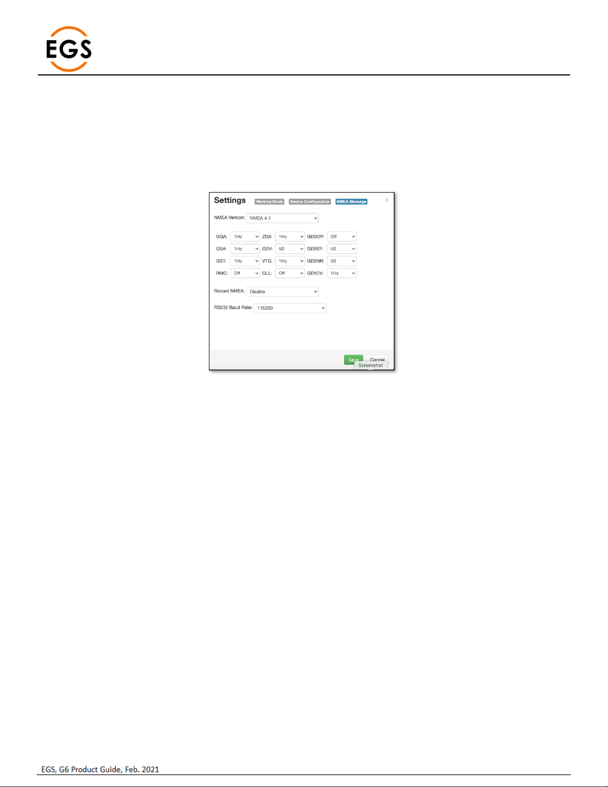
3.6.3 NMEA Message
This allows for NMEA Messages to output through the 5-Pin Lemo cable. The user may select the message and the output frequency.
Current messages supported are:
•GGA
•GSA
•GST
•RMC
•ZDA
•GSV
•VTG
•GLL
•GEDOP
•GEREF
•GESNR
•GEVCV
Figure 25: NMEA Output Settings
3.6.3.1 NMEA Version
This will set the NMEA standardized version. Current versions available for output are:
•NMEA 3.1
•NMEA 4.1
3.6.3.2 Record NMEA
This enables / disables the NMEA output through the 5-Pin Lemo.
3.6.3.3 RS232 Baud Rate
This feature sets the output baud rate out of the 5-Pin Lemo cable. Output rates available are:
•9600
•19200
•38400
•57600
•115200 (default)
Page | 20
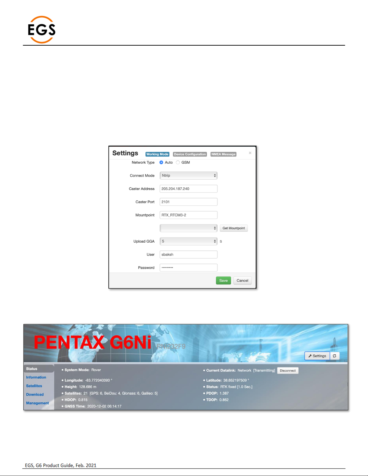
3.6.4 Relay Mode
The Relay mode feature on a G6N rover uses the integrated cell modem to receive differential corrections and relay these corrections
over the integrated UHF radio. This mode allows for several G6N rovers to operate in the field while utilizing only one activated SIM
card plan.
The steps outlined below show how to configure the G6N rover to operate in relay mode.
3.6.4.1 Connect to G6N Web UI
Ensure the WiFi is enabled on the G6N. Using a browser, type in 192.168.10.1 to load the Web UI. Type in ‘admin’ and ‘password’ to
login to the G6N.
3.6.4.2 Configure the G6N as a Rover
From the Web UI, go to Settings > Working Mode. Select ‘Rover’ and the datalink as ‘Network’. Configure the preferred NTRIP
connection.
Figure 26: NTRIP Configuration
3.6.4.3 Confirm RTK Corrections
Confirm the G6N is receiving corrections and in RTK mode from the Status page.
Figure 27: RTK via NTRIP
Table of contents


