Manufactured by ELPRO INNOTEK S.p.A.
Via Piave, 23 -
I-31020 S.Pietro di Feletto (TV) -
ITALY
Tel. +39-0438.450879 -
Fax. +39-0438.455628
Fig. 8
PV
1
PV
1
PR
LV
Fig. 7
PR
1
PV
1
PV
LR
GUARANTEE
Guarantee period : 24 months from the production date placed inside.
In this period if the appliance has any malfunction due to defective component, it will
be repaired or replaced by the manufacturer.
The guarantee doesn't cover the plastic box
The assistance will be perfomed at the manufacturer site
14 - Memory data transfer : from receiver to backup memory (fig. 7)
Procedure
1) Slot-in the backup memory into theconnector CT .
2) Keep the button PR pressed downuntil the RED led LR turns on.
3) Push the button PV for1 sec and then confirm with PV again.
4a) If the memory is empty, the led GREEN will turn ON and, after 2 sec., both the led
LR and LV will blink3 times simultaneously.
4b) If the memory is full the ledswill turn on showing that the memory isfull.
To goon, and make the transfer, confirm by pressing the button PV.
At this point the led RED LR willturn ON
At the end of the transfer, both the led LR and LV will blink 3 times simultaneously to
confirm the success of the data transfer.
RECEIVER MEMORY
RECEIVER
MEMORY
LR
LV
LR
LV
17 - Timing diagram for DATA0, DATA1 and CLOCK
DATA1
CLOCK
DATA0
50 µS
2 mS
P1 P2
Facility code Serial number
16 - Output signal structure
26 bit Wiegand
LEGEND :
P1 = Even parity of the first 12 bits ( bit 1)
Facility code = 8 bit ( bit 2 .. , bit 9)
Serial Number = 16 bit ( bit 10 .. , bit 25)
P2 = Odd parity of the last 12 bit ( bit 26)
P1 P2
Facility code Serial number
30 bit Wiegand
LEGEND :
0000 = 4 bits fixed to “0”
Facility code = 8 bit ( bit 6 .. , bit 13)
Serial Number = 16 bit ( bit 14 .. , bit 29)
P2 =
P1 = Even parity of the first 14 bits ( bit 1)
Odd parity of the last 14 bit ( bit 30)
0000
13 - Memory erasure ( fig. 6)
This means that all the transmitters will be erased and the memory will be brought to its
previous the state, before the initialisation.
Procedure
1) Press PR until the led RED turns ON
2) release PR and then keep simultaneously for 4 sec until the 2 leds
flash 3 times.
With this procedure, you will erase completely the memory.
PR and PV pressed
PR LR PR PV
LR
LV
244
Fig. 6
Fig. 9
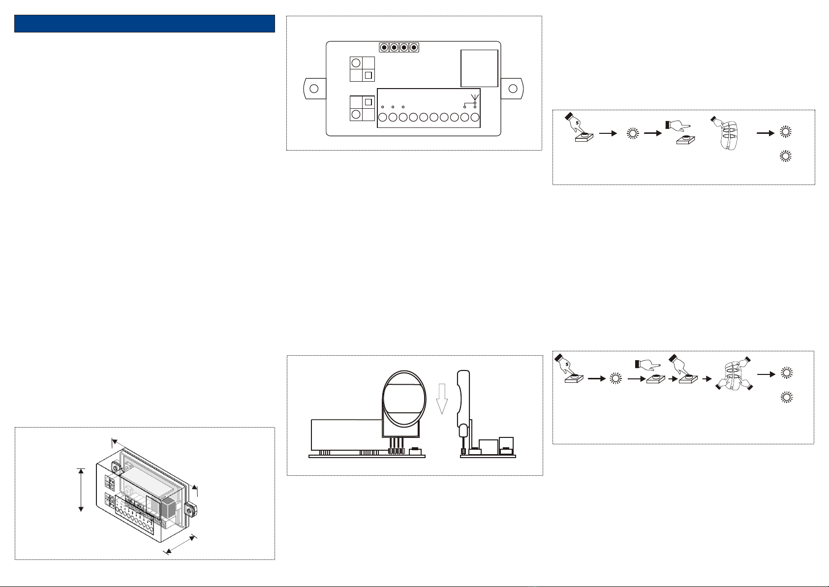
15 - Memory data transfer : from backup memory to receiver (fig.8)
Procedure
1) Slot-in the backup memory into theconnector CT .
2) Keep the button PV pressed downuntil the GREEN led LVturns on.
3) Push the button PV for1 sec.
4a) If the memory is empty, the led GREEN will turn ON and,after 2 sec., both the led
LR and LV will blink3 times simultaneously.
4b) If the memory is full the ledswill turn on showing that the memory isfull.
To goon, and make the transfer, confirm by pressing the button PR.
At this point the GREEN led LV will turn ON
At the end of the transfer, both the led LR and LV will blink 3 times simultaneously to
confirm the success of the data transfer.
12 - Output message format changement
With the following procedure it is possible to change the format of the output wiegand
message, by setting it in 26 or 30 bits.
Procedure
Press and keep pressed the button GREEN for 4 sec. until the led GREEN turns on and
then release the button. At this point the led GREEN will show the current message
according to the following rule:
GREEN LED ON --> 26 bits message
--> 30
To change the message type, press the button RED for one sec.: you will change the type
from 26 to 30 or from 30 to 26 . The GREEN led will change to confirm the changement.
GREEN LED BLINKING bits message
11 - Memory full and auto-deleting of the never used transmitters.
The self learning is allowed to any allowed transmitter. It can happen, anyway, that the
memorisation of a new transmitter is tried when the memory is already full.
In this case the main microprocessor deletes the transmitter S/N less used in order to
create room and to enable the new one
On the firmware has been created
À chaque émetteur est associé, en effet, un compteur qu'il tient compte de la fréquence de
jouissance. L'utilisateur de l'émetteur effacé peut, à son tour, re-mémoriser le propre code
au détriment d'un autre, en appuie la clef de l'émetteur qui 3 fois consécutives.
Périodiquement est possible d'effacer toute la mémoire , si trop pleine, en permettant de
nouveau l'auto-mémorisation.
10 - Memorisation of the user transmitters
After the initialisation, you need to memorise the transmitters.
You can memorise only the transmitters with the same FACILITY CODE introduced during the
initialisation phase.
The memorisation of the transmitter can be done directly by the final user, by following the
procedure below.
Procedure
Push 3 times the key of the transmitter which has to be memorised.
After the third transmission received, the receiver will send out the corresponding signal along
the Wiegand output and will flash once both the led RED and GREEN simultaneously.
From this time on the receiver will check the FACILITY CODE, S/N and ROLLING CODE
COUNTER of any incoming signal, by disabling in this way the access ot any signal which
doesn’t respect the right specifications.
IS-RXWCDUK Rev. 1 del 29/10/07