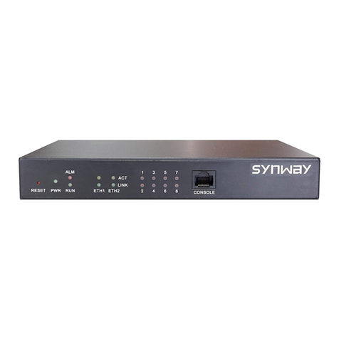
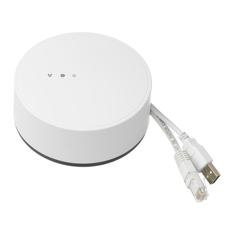
EI SmartLINK Ei1000G User manual

1
Ei1000G
Installation Manual
SmartLINK Gateway
Read and retain carefully for as long as the product is being used. It contains vital information on the operation
and installation. The leaflet should be regarded as part of the product.
If you are just installing the unit, the leaflet MUST be given to the householder. The leaflet is to be given to
any subsequent user.

2

3
Contents
1. Introduction
2. Overview
3. Gateway Installation
4. Locating your Gateway
5. SmartLINK App installation process
App download and setup
App and system login
Property information
Scan gateway
Add a device
What if I don’t have a QR code on my device?
Seal and upload the system
6. Additional Features
Gateway signal check
View system data
Send report
7. System Upgrade
Add additional device
Remove / replace device
8. Service and Guarantee
9. Technical Specifications
4
4
7
8
10
10
10
11
12
13
15
16
17
17
18
19
20
20
23
25
26
Page

4
1. Introduction
The following information is aimed at providing guidance on how to correctly install Ei Electronics Alarms in a
Gateway System via the SmartLINK installation App. It is necessary to use the app to push the correct installation
data to the ‘SmartLINK Cloud Portal’.
2. Overview
The SmartLINK Gateway and Cloud portal service is another new and exciting innovation from Ei Electronics. The
Cloud portal allows clients to view and manage their installed stock of Alarms, it also facilitates fault monitoring
and maintenance of installed Alarms enabling clients to manage the maintenance, repair, and replacement of
systems more efficiently and effectively.
Features include:
• Alarm status
• Fault status
• Text alert and e-mail notification capability for both Fire/CO and fault events.
• Installation reports
• Replacement and fault reports
Alert capability is provided via the Cloud portal setting which allows alert contacts to be created and assigned
to each property for both Alarm and service events.
A Gateway is necessary in the system to push events from the Alarms to the SmartLINK Cloud portal as they
happen. The Gateway is a roaming 2G GSM-based device that ensures the maximum connectivity possible
without the need for local broadband or Wi-Fi services.

5
Antenna
House
Code ResetOff / On Test
2 3 4 5 6 7 81
Antenna
House
Code Reset
Off / On Test
Panel / Icon Overview
1On / Off battery switch
2Antenna
3GSM LED
4RF LED
5House Code button
6Test button
7Power LED
8Reset button

6
Add in SmartLINK compatible devices for a fully cloud connected system
SmartLINK
Simply plug in Ei3000MRF
SmartLINK modules for
wireless interconnection
between Alarms and
communication with the
Ei1000G SmartLINK Gateway
- Live monitoring of connected
SmartLINK Alarm systems
- Details of system installations
- Notifications of Alarm
activations and system events
via alert, text message
or e-mail
Setup the Cloud portal to delive
r
Install the Gateway to
provide communication to
the SmartLINK Cloud Portal

7
3. Gateway Installation
GSM Signal Strength Test:
Prior to installing your Gateway, we recommend that you perform a short GSM survey with the Gateway to
ensure the location you plan to mount the Gateway in is suitable. You can do this without applying mains power
to the Gateway, simply turn on the Battery Switch located at the top of the Gateway (see figure 1) and attach
the Antenna, (located in the bag supplied) by rotating the gold nut clockwise and ensuring it is tightened fully
in place by hand.
Warning: Do not leave your Gateway on battery power only for longer than 24 hours.
The Gateway GSM signal strength can be checked by pressing and
holding the Test button on the Gateway and counting the yellow
flashes. When checking the signal strength its important that you
hold the Gateway with the Antenna in the vertical orientation.
If your Gateway is indicating a poor signal strength we recommended you move to a location that provides
you with the best signal strength. Also please note the advice in the next section on “Locating your Gateway”.
Battery
Off / On
Switch
Antenna
Antenna
House
Code Reset
Off / On Test
Fig. 1
Number of Flashes Signal Strength
4 Excellent
3 Good
2 Average
1 Poor

8
4. Locating Your Gateway
Please mount your Gateway in a suitable location. We recommend your Gateway is mounted on a wall, in a
hallway, or another suitable area provided you have sufficient GSM signal strength. Please ensure your Gateway
is mounted with the Antenna in the vertical orientation. Consideration should be given to the location of the
Gateway to avoid any unnecessary interaction with the Gateway once installed. Before you mount your Gateway
please ensure you carry out our simple GSM signal strength test - see section 3.
Do not mount your Gateway in a steel box or close to
large metal objects such as boilers, as this will reduce
your GSM signal strength.
The mounting bracket can be detached from the
Gateway and secured to the wall with the screws
provided (see figure 2).
* Important * - Make sure the mounting plate is
positioned ‘THIS WAY UP’ on the wall before fixing.
Slide the Gateway onto the mounting plate. Your
Gateway comes pre-wired with a 2 core cable and
strain relief grommet, this allows you to easily wire
your Gateway directly into an un-switched Flex spur.
* Important *
Note plate
orientation
Fig. 2

9
Warning: Wiring must be installed in compliance with local regulations.
Warning: This product should only be installed in a location where an all-pole mains switch
in accordance with Annex L of EN62368-1 is incorporated in the electrical installation of the
building. As the device is permanently connected to mains supply, the appropriate disconnect
device shall be provided as part of the building installation.
Warning: Please ensure you turn on the battery backup switch to its ON position as per figure 1
on page 7. (If you have not done so already during the GSM signal strength check). Failure to carry
out this step will result in no battery backup capability if power is lost to the Gateway.
Now you can energize the mains supply to the Gateway, the green LED will illuminate, at the same time the blue
LED will flash for 30-40 sec (see Panel / Icon Overview on page 5). This indicates that the Gateway is powering
up and connecting to the SmartLINK server. Please do not start the installation procedure until the Blue LED has
stopped flashing.
Gateway LED Indicator Table
Action Operation Green LED Blue LED Yellow LED
Energise mains supply Power up On Flashing (30-40 sec) On (2 sec)
Hold Test button (4 sec) Button Test / Signal Strength Test On Flashing Flashing
Hold House Code button until blue LED lights Enter House Code mode On Flashing Off
Hold House Code button until blue LED lights Exit House Code mode On On (1 sec) Off
Hold House Code button until blue LED flashes Factory reset On On (1 sec) Off

10
5. SmartLINK App Installation Process
Install and wire your Alarms as normal following the relevant instruction manuals.
App Download and Set up
Download the SmartLINK app from the Google Play or iTunes app store.
Step 1: App and System Login
In order to log into the App, you will need to be set up on the SmartLINK Cloud Portal as an official installer
linked to the Client you are undertaking the work for. Please contact your local client administrator to arrange
a username and password.
*Note, the following screen images are representative only, app screens may
differ slightly depending on your device operating system, age, and model.

11
Step 2: Property information
Once logged select ‘Add Installation’ from the main menu and proceed to input the property details. If you
use UPRNs you should input the relevant UPRN (Unique Property Reference Number) I/D for this property. The
app uses an auto lookup address feature. Type in the postcode for the property and press ‘Search’. You will be
presented with the actual address or a list of addresses related to that postcode. Select the correct address and
the App will automatically fill in the rest of the address info.
Lastly please select your client name, if you are approved to work for multiple clients on the SmartLINK system
you will be presented with a list to choose from.

12
Step 3: Scan Gateway
Once you start the installation process the first step is to scan the Gateway prior to scanning or installing any
other device, this can be done by scanning the QR code label located on the underside of the Gateway. Press
‘Scan’ and move the phone over the QR code until the serial and model is captured. Once captured, enter its
location from the drop down-list, place the Gateway into House Code mode and confirm the Gateway flash
count indicated on the App.
* Note the Gateway and other compatible Accessories will have only one QR code label, scanning this will input
the RF serial number, model number and replace by date of this device. All other Alarms require you to scan
both the RF module QR code label and the Alarm QR code label.

13
Step 4: Add a device
To add a device simply click the ‘Add Unit’ button and follow the on screens instructions. If your Alarm and
RF Module have a QR code label you can press the ‘Scan’ button and scan firstly the RF module label followed
secondly by the Alarm / device model label. This captures the RF serial number, the device model and the replace
by date of the Alarm. If either the Alarm or the Module does not have a QR code, choose ‘Skip’ and proceed to
step 4A on page 15.
Once the RF Serial number and Alarm model is captured select the location from the dropdown list. Place the
device into House Code mode and confirm both the Gateway and device flash count as indicated on the App.
*Note its critical that you check the device and Gateway flash count match.

14
Repeat Step 4 for each device you want to add to the system.
Each unit’s blue LED should flash once for every unit in House Code, including the Gateway, with the exception
of the Ei3028, which has two flashes, due to its ability to detect both Carbon Monoxide and Fire. Please refer to
the table above to indicate the number of flashes by device model.
Models Number of blue flashes
per device
Ei160e Series 1
Ei2110e 1
Ei208 Series 1
Ei650 / 603 Series 1
Ei1000G Gateway 1
Ei3014, 3016, 3018, 3024 1
Ei3028 2

15
Step 4A: What if I don’t have a QR code on my device?
Even if your device does not have a QR code label you can still use the installation app to set up your Gateway
system. Just click on the ‘Skip’ button to take you to the next page. Here you will be asked to fill in the device
location along with the device ‘Model’ and ‘Replace by Date’ both of which are located on the side of the
Alarm. Again, place the device into House Code mode and confirm both the Gateway and device flash count.

16
Step 5: Seal the system
Once you have added all the necessary devices to the system and you have confirmed both the Gateway
and device flash count is correct you can click on the ‘Finish’ button. This will bring you to the ‘House Code
Exit’ screen. Follow the on-screen instruction and then click ‘Next’. The Gateway and App will now push the
installation data to the SmartLINK Cloud Portal.
A summary of the complete installation and the signal strength data from the Gateway will be presented.
Finally: Commission your system by button testing each Alarm individually.

17
Note: In the case of an RF communication error it may sometimes be necessary to factory reset the units in a
system, and House Code the units again. To factory reset the Gateway, hold the House Code button until the blue
LED begins to flash, and then release. Alarm heads can also be reset in this way. Once all units have been reset,
the House Coding can be started again as normal.
6. Additional Features
Gateway Signal Check
The signal check is a guide on the RF link between the Gateway and each device. Direct range is indicated by a
signal strength graph showing the relative strength of the communication path between the device and Gateway.
L1 indicates the device is not in direct range to the Gateway and can only communicate to the Gateway via another
device. While this is not ideal this will still suffice for critical messages.
Family Direct Range L1 L2
Ei3000 Series Good at all levels Good Poor
Ei160e Series Good >1 bar OK limited messages *
Ei207 / 208 Series Good >1 bar OK limited messages *
Ei650 / 603 Good >1 bar OK limited messages *
Accessories Good >1 bar OK limited messages *
*3000 series devices repeat all messages, all other ranges repeat limited messages. In all cases, once the units
are House Coded, Fire and CO alarm activation events are repeated.

18
View System data
In order to access a property’s system data, you can select ‘View Installations’ from the main menu. Select the
property from the Recent install list or Search for the property via the search function bar. Once you have
selected the property you can click on any device and access the device information and event history.

19
Send Report
Once you have completed an installation you can send the summary installation report via email to a client or
back to the office as a static record of the installation for further administration.
Simply click “Send Report” in the system view and type in the email address. For your convenience, the app can
store the last used email address.

20
7. System Upgrade
Add additional device
To add a device to an existing system simply select the system from the Recent installations list or use the search
function. Once you select the relevant property click on the ‘Edit’ button at the top right-hand corner then select
‘Add Unit’. Scan the QR codes on the device or use the Skip function if no QR codes are available. Enter the device
details and select Next. Place the device in House Code mode.
Table of contents
