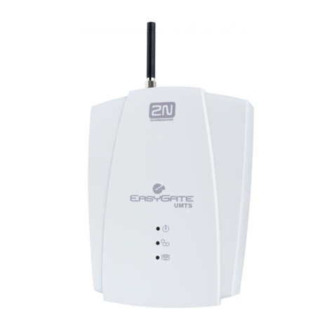
2N stargate User manual

2N®StarGate / 2N®StarGate UMTS
2NBlueStar, 2NBlueTower
User Manual
Version 3.0.0
Firmware 2.30.02 www.2n.cz

The 2N TELEKOMUNIKACE a.s. joint-stock company is a Czech manufacturer and supplier
of telecommunications equipment.
The product family developed by 2N TELEKOMUNIKACE a.s. includes GSM gateways,
private branch exchanges (PBX), and door and lift communicators.
2N TELEKOMUNIKACE a.s. has been ranked among the Czech top companies for years
and represented a symbol of stability and prosperity on the telecommunications market
for almost two decades. At present, we export our products into over 120 countries
worldwide and have exclusive distributors on all continents.
2Nis a registered trademark of 2N TELEKOMUNIKACE a.s.. Any product and/or other
names mentioned herein are registered trademarks and/or trademarks or brands
protected by law.
2N TELEKOMUNIKACE administers the FAQ database to help you quickly find information
and to answer your questions about 2N products and services. On faq.2n.cz you can find
information regarding products adjustment and instructions for optimum use and
Declaration of Conformity
2N TELEKOMUNIKACE a.s. hereby declares that the 2NStarGate product complies with
all basic requirements and other relevant provisions of the 1999/5/EC directive. For the
full wording of the Declaration of Conformity see the CD-ROM enclosed and at www.2n.cz.
The 2N TELEKOMUNIKACE company is a holder of the ISO 9001:2000 certificate. All
development, production and distribution processes of the company are managed by this
standard and guarantee a high quality and advanced technical level of and a professional
approach to all of our products.

Table of Contents
1. Product Overview...............................................................7
1.1 System............................................................................................................................. 8
2N® StarGate.................................................................................................................... 8
2N®BlueStar .................................................................................................................. 10
2N®BlueTower............................................................................................................... 12
1.2 Product Description..................................................................................................... 16
Basic Features................................................................................................................ 16
Advantages of 2N®StarGate/BlueStar/BlueTower ........................................................ 16
1.3 Innovations ................................................................................................................... 18
1.4 Terms and Symbols Used ........................................................................................... 19
Manual Symbols............................................................................................................. 19
Future Functions............................................................................................................. 19
2. Description and Installation............................................21
2.1 Plug-In Boards.............................................................................................................. 22
Basic CPU Board............................................................................................................ 22
Enhanced CPU Board.................................................................................................... 25
AUX Board...................................................................................................................... 29
PRI Board....................................................................................................................... 32
VoIP Board..................................................................................................................... 36
GSM / UMTS Board ....................................................................................................... 38
2.2 Antenna and Antenna Splitters................................................................................... 44
Antenna Splitter.............................................................................................................. 44
Directional Antenna........................................................................................................ 46
Discreet Antenna............................................................................................................ 48
Directional Antenna Connection Cable .......................................................................... 48
2.3 Gateway Rack Configuration ...................................................................................... 50
2.4 Installation..................................................................................................................... 52
Product Completeness Check........................................................................................ 52
Installation Conditions .................................................................................................... 52
VoIP Connection............................................................................................................. 53
ISDN PRI Connection..................................................................................................... 54
Licence Limitations......................................................................................................... 56
GSM / UMTS Network Restriction.................................................................................. 57
Basic CPU Firmware...................................................................................................... 57
Potential Problems of GSM / UMTS Networks............................................................... 58
Mounting......................................................................................................................... 59
Main Installation.............................................................................................................. 60
3. Configuration....................................................................63

3.1 Important Default Settings .......................................................................................... 64
3.2 Quick Step-by-Step Manual......................................................................................... 65
Quick Step-by-Step Manual for ISDN PRI Card............................................................. 65
Quick Step-by-Step Manual for VoIP Card .................................................................... 66
Quick Step-by-Step Manual for 2N®SIM Star................................................................ 67
3.3 System Upgrade............................................................................................................ 69
3.4 Configuration Tool ....................................................................................................... 70
Program Installation ....................................................................................................... 70
Program Running ........................................................................................................... 70
Gateway Connection...................................................................................................... 71
Main Menu and Button Bar............................................................................................. 71
Configuration Menu........................................................................................................ 85
Off-Line Configuration .................................................................................................... 86
3.5 Enhanced CPU Configuration................................................................................... 111
Serial Console Access ................................................................................................. 111
Web Browser Access ................................................................................................... 113
3.6 2N® External Routing Machine Configuration........................................................... 127
Installation .................................................................................................................... 127
Configuration................................................................................................................ 129
ERM Control................................................................................................................. 131
Description of ERM Function........................................................................................ 132
ERM Database Structure ............................................................................................. 132
3.7 2N®SIM Star System................................................................................................... 135
Product Purpose........................................................................................................... 135
2N®SIM Star Key Components .................................................................................. 135
SIM Client Configuration .............................................................................................. 135
3.8 Voice CallBack Centre Configuration ...................................................................... 136
Function Scheme ......................................................................................................... 136
Installation and Licences.............................................................................................. 137
Configuration................................................................................................................ 141
4. Advanced Configuration ...............................................143
4.1 List of AT Commands ................................................................................................ 144
Basic Commands .................................................................144
Configuration commands....................................................144
4.2 List of Status Codes................................................................................................... 150
4.3 Trace............................................................................................................................ 155
4.4 List of LOG Events..................................................................................................... 157
4.5 Statistics...................................................................................................................... 159
4.6 CDR Line Description ................................................................................................ 160

5. Technical Parameters....................................................161
5.1 StarGate Technical Parameters ................................................................................ 163
5.2 BlueStar Technical Parameters ................................................................................ 165
5.3 BlueTower Technical Parameters............................................................................. 167
6. Supplementary Information ..........................................169
6.1 Regulations and Directives ....................................................................................... 170
6.2 Troubleshooting......................................................................................................... 171
6.3 List of Abbreviations.................................................................................................. 173
6.4 General Instructions and Cautions .......................................................................... 175


7
1
1. Product
Overview
In this section, we introduce the 2N®StarGate / BlueStar / BlueTower product,
outline its application options and highlight the advantages following from its use. This
section also includes safety instructions.
Here is what you can find in this section:
System
Product Description
Innovations
Terms and Symbols Used

System
1.1
8
1.1 System
This user manual is designed for three types of gateways. All the gateways have the
same features and differ in the maximum capacity of the GSM / UMTS channels used.
2N® StarGate
Basic Dimensions
2NStarGate is the biggest GSM gateway in the 2NPRI gateways family. The
front side is open, equipped with slots for plug-in boards with front panels. The panel
includes the main switch. In case not all GSM / UMTS cards are plugged in, the vacant
front section must be covered with a fixed panel(s).
The whole backside is covered with a panel with a built-in active fan, which is
automatically switched on whenever the power supply temperature exceeds 7. The
main power supply unit is located in front of the fan. The bottom and upper sides are
covered by perforated sheet and the assembly flanges are provided with handrails.
The system bus is designed as a printed circuit board (PCB) with DIN
connectors and fitted to the inner subrack carrier profiles.
Front Side Division
The subrack width is divided into an 8HP-wide mains panel and 19x4HP-wide
modules in the following sequence (from right to left):
VoIP version
Fixed panel with a main switch (AC type) or power connectors (DC type)
8HP
VoIP card
4HP
Basic or enhanced CPU card
4HP
AUX card
4HP
GSM or UMTS cards (one for two GSM / UMTS channels)
Remaining space (each 4HP)
ISDN PRI version
Fixed panel with a main switch (AC type) or power connectors (DC type)
8HP
Basic or enhanced CPU card
4HP
AUX card
4HP
1ISDN PRI or 2ISDN PRI card
4HP
GSM or UMTS cards (one for two GSM / UMTS channels)
Remaining space (each 4HP)

System
1.1
9
Examples of Used Types
Empty 2NStarGate Rack
GSM Boards, Basic CPU, VoIP Interface and AC Power Supply
UMTS Boards, Enhanced CPU, 2 ISDN PRI Interfaces and AC
Power Supply
Note
Please keep all cards in the right positions. Wrong positions will cause
malfunction of the whole system!
In the case of VoIP card replacement by ISDN PRI (and vice versa) please
read the instructions in Section 2 Installation.

System
1.1
10
Power Supply
The system uses an industrial power supply unit with natural cooling and an
auxiliary external fan, which is switched on automatically whenever the power supply
power supply unit is designed with a 30% reserve
even under the maximum load.
Power supply types
Internal 90-260V / 50 60 Hz (output 5V / 30A);
Internal 48 DC (output 5V / 30A).
The type of the power supply unit to be used depends on the part number.
Caution
Make sure that the incoming supply is matching the requested values!
High voltage may cause a serious injury or death!
Tip
You are recommended to connect the gateway to the UPS system.
2N®BlueStar
Basic Dimensions
2NBlueStar is a GSM gateway from the 2NPRI gateway family with the
capacity up to 16 GSM / UMTS channels
the height of 3U and depth of 360mm. The front side is open, equipped with slots for
plug-in boards with front panels. The panel includes the main switch. In case not all
GSM / UMTS cards are plugged in, the vacant section of the front side must be
covered with a fixed panel(s). An optional antenna splitter can be installed.
The whole backside is covered with a panel with a built-in active fan, which is
automatically switched on in case the power supply
main power supply unit is located in front of the fan. The bottom and upper sides are
covered by perforated sheet and the assembly flanges are provided with handrails.
The system bus is designed as a printed circuit board (PCB) with DIN
connectors and fitted to the inner subrack carrier profiles.

System
1.1
11
Front Side Division
The subrack width is divided into an 8HP-wide mains panel and 19x4HP-wide
modules in the following sequence (from right to left):
VoIP version
Fixed panel with a main switch (AC type) or power connectors (DC type)
8HP
VoIP card
4HP
Basic or enhanced CPU card
4HP
AUX card
4HP
GSM or UMTS cards (one for two GSM / UMTS channels)
Remaining space (each 4HP)
ISDN PRI version
Fixed panel with a main switch (AC type) or power connectors (DC type)
8HP
Basic or enhanced CPU card
4HP
AUX card
4HP
1ISDN PRI or 2ISDN PRI card
4HP
GSM or UMTS cards (one for two GSM / UMTS channels)
Remaining space (each 4HP)
Examples of Used Types
BlueStar 8 GSM Boards, Basic CPU, 2 ISDN PRI Interfaces, Integrated Antenna
Splitter and AC Power Supply
Note
Please keep all cards in the right positions. Wrong positions will cause
malfunction of the whole system!
In the case of VoIP card replacement by ISDN PRI (and vice versa) please
read the instructions in Section 2 Installation.

System
1.1
12
Power Supply
The system uses an industrial power supply unit with natural cooling and an
auxiliary external fan, which is switched on automatically whenever the power supply
power supply unit is designed with a 30% reserve
even under the maximum load.
Power supply types
Internal 90-260V / 50 60 Hz (output 5V / 30A)
Internal 48 DC (output 5V / 30A)
The type of the power supply used depends on the part number.
Caution
Make sure that the incoming supply is matching the requested values!
High voltage may cause a serious injury or death!
Tip
You are recommended to connect the gateway to the UPS system.
2N®BlueTower
Basic Dimensions
2NBlueTower is the smallest of the 2NPRI gateway family, featuring the
subrack of the height of 3U, width of 29HP and depth of 320mm. The front side is
open, equipped with slots for plug-in boards with front panels. The panel includes the
main switch. In case not all GSM / UMTS cards are plugged in, the vacant section of
the front side must be covered with a fixed panel(s). An optional antenna splitter can
be installed.
The whole backside is covered with a panel with a built-in safety-fuse box and
power socket. The main power supply unit is inside the system and is fully designed
for passive cooling. The bottom and upper sides are covered with EMC sheet.
The system bus is designed as a printed circuit board (PCB) with DIN
connectors and fitted to the inner subrack carrier profiles.
Front Side Division
The subrack width is divided into 7x4HP-wide modules in the following
sequence (from right to left):
VoIP version
VoIP card
4HP

System
1.1
13
Basic or enhanced CPU card
4HP
AUX card
4HP
GSM or UMTS cards (one for two GSM / UMTS channels)
Remaining space (each 4HP)
ISDN PRI version
Basic or enhanced CPU card
4HP
AUX card
4HP
1ISDN PRI or 2ISDN PRI card
4HP
GSM or UMTS cards (one for two GSM / UMTS channels)
Remaining space (each 4HP)
Examples of Used Types
oards, Enhanced CPU, VoIP Interfaces and Integrated

System
1.1
14
Antenna Splitter
wer with 2 UMTS Boards, Basic CPU, 2 ISDN PRI Interfaces and Integrated
Antenna Splitter
Note
Please keep all cards in the right positions. Wrong positions will cause
malfunction of whole system!
In the case of VoIP card replacement by ISDN PRI (and vice versa) please
read the instructions in Section 2 Installation.
Power Supply
The system uses an industrial power supply unit with natural cooling and an
auxiliary external fan, which is switched on automatically whenever the power supply
temperature excpower supply unit is designed with a 30% reserve
even under the maximum load.
Power supply types
Internal 90-260V / 50 60 Hz (output 5V / 30A);
Internal 48 DC (output 5V / 30A).
The type of the power supply used depends on the part number.
Caution
Make sure that the incoming supply is matching the requested values!

System
1.1
15
High voltage may cause a serious injury or death!
Tip
You are recommended to connect the gateway to the UPS system.

Product Description
1.2
16
1.2 Product Description
Basic Features
2NStarGate / BlueStar / BlueTower is a compact yet highly sophisticated system. It
supports full remote supervision and configuration via an IP network or using an
external modem over a BRI-ISDN and analogue line, or over a B channel in a PRI-
ISDN trunk. The system has been designed and works with a lot of highly
sophisticated functions, which make it fully client-oriented and highly reliable in
cooperation with both GSM networks and ISDN. In addition, it provides full monitoring
and comfortable (web interface) configuration without functional limitations.
Configuration alterations can be made without resetting, i.e. under full operation. Hot-
swappable plug-in GSM / UMTS boards, which can be swapped under full operation
including SIM cards, are a matter of course. The use of up to eight SIM cards per GSM
/ UMTS module in combination with an intelligent SIM card switching tool and detailed
statistics upgrade this system into a powerful LCR tool. There is also support of
remote SIM cards (2NSIM Star) and an external LCR machine (2NExternal Routing
Machine). High product stability is achieved by the fact that the gateway is
programmed in the ASM, i.e. an OS-FREE system. Two independent 30MHz Philips
microprocessors provide an error-free operation, high speed, automatic fault detection
and easy upgrade. The system also features easy installation, simple operation and
easy replacement of defective parts as it is composed of plug-in boards that
communicate independently along system buses. As already mentioned, the system
allows for an easy detection of defective parts, automatic locking against use and easy
replacement (hot-swap). Thanks to the above- mentioned properties, the system can
be installed and configured successfully within one hour!
Advantages of 2N®StarGate/BlueStar/BlueTower
Compact size, modularity and hot-swappable solution;
Up to 32 GSM / UMTS modules (16 in BlueStar, 8 in BlueTower);
Up to 256 SIM cards in a system (StarGate);
Worldwide use GSM / UMTS boards support all standard GSM
(850/900/1800/1900MHz) and UMTS (850/1900/2100MHz) bandwidths;
Antenna splitters and a high-gain antenna;
Support of up to two ISDN PRI (DSS1) or one VoIP (SIP) connections;
Sending / receiving SMS;
A large memory for detailed Call Data Records (CDR);
Detailed call statistics generating;
Quick start - being free of an operating system (programmed in the processor
code), the system is completely ready within 30 seconds after power
on/restart. Of course, the full function time of all GSM modules depends on
the current load and capacity of the GSM networks to which the gateway is
connected;

Product Description
1.2
17
Intelligent call processing Least Cost Routing (LCR), SMS and Voice
CallBack, Auto CLIP routing, DISA dial-in;
Intelligent selection of GSM / UMTS module to be used;
Support of remote SIM card function (2NSIM Star);
Possibility to replace internal LCR with an external solution (2NERM);
Remote control, configuration and firmware upgrade;
High connection rate and ASR, low PDD.

Innovations
1.3
18
1.3 Innovations
The manufacturer is committed to improving the control program that is
included in this product (referred to as firmware and bootware). The used ISP
(In System Programming) technology gives you the possibility to store the
latest control program in your StarGate / BlueStar / BlueTower gateway by
means of a standard computer. For the most recent version of the
configuration tool and additional software together with all necessary
components refer to www.2n.cz and for necessary instructions see the
System Upgrade section hereof. It is recommended that you use the most
recent version of the program to avoid unnecessary problems and
shortcomings that have already been eliminated.
If you program your StarGate / BlueStar / BlueTower parameters by means of a
computer, you need the PRI config program or a web browser (when using the
eCPU web interface ). Find the latest version of this programming tool at
www.2n.cz as well.
At www.2n.cz you will also find the most recent version of this manual in
the popular PDF format. We recommend you to use it especially in connection
with the control program upgrade as it introduces new useful functions.
Preliminary information on functions that are not yet available are typed on a
light grey background or use grey letters instead of black ones.

Terms and Symbols Used
1.4
19
1.4 Terms and Symbols Used
Manual Symbols
Safety
Always abide by this information to prevent personal injury.
Warning
Always abide by this information to prevent damage to the device.
Caution
Important information for system functionality.
Tip
Useful information for quick and efficient functionality.
Note
Routines or advice for efficient use of the device.
Future Functions
A grey-marked text in this document specifies the
2N®StarGate/BlueStar/BlueTower functions that will be supported in the future.

Other manuals for stargate
3
This manual suits for next models
3
Table of contents
Other 2N Gateway manuals
Popular Gateway manuals by other brands

Ursalink
Ursalink UG87 quick start guide

Zhejiang Third Net Technology Co.
Zhejiang Third Net Technology Co. TN-IVS-8000 user manual

HBM
HBM SomatXR CX27C-R operating manual

Sys Tec Electronic
Sys Tec Electronic GW-003 System manual

RisingHF
RisingHF RHF2S008P4G user manual

ZyXEL Communications
ZyXEL Communications VMG8029 quick start guide