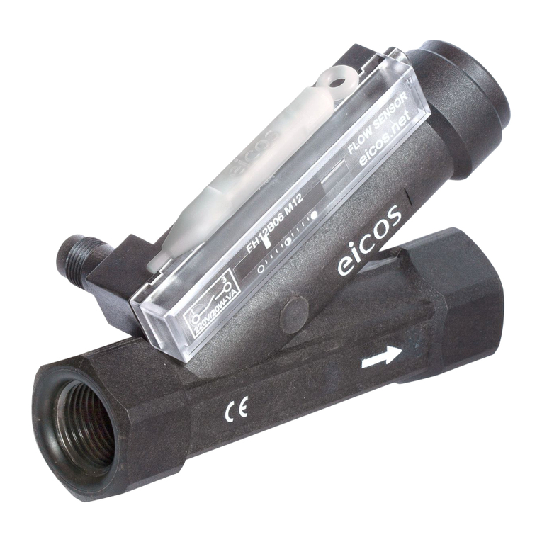
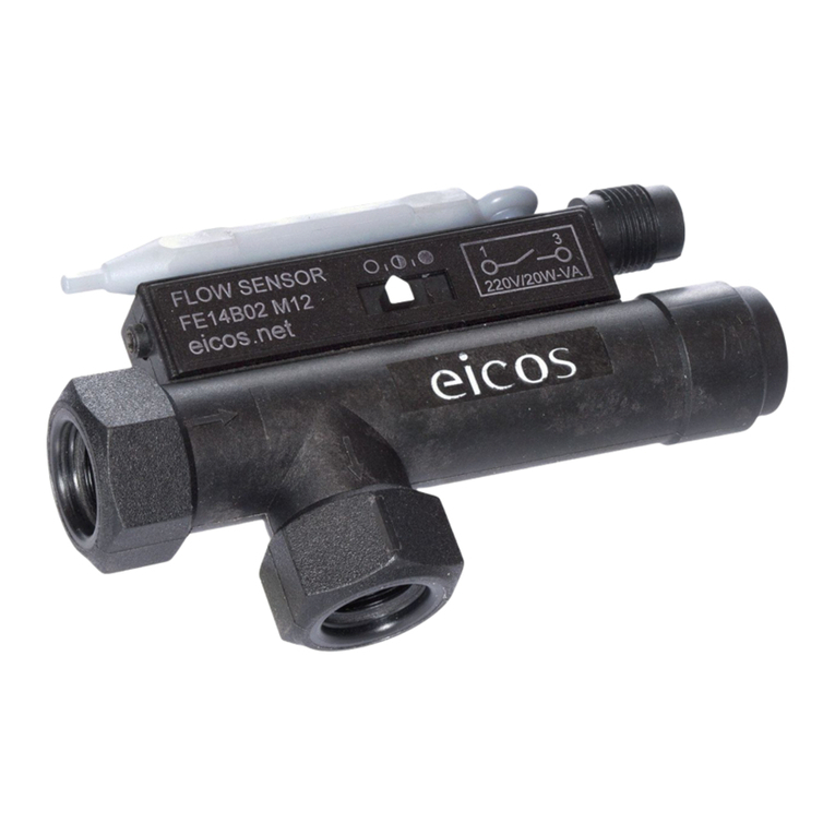
eicos FC34B02-M12 User manual

40m20m
L2
A1
A2
A1+
A2-
+
+
R
Reed Switch Reed Switch
2K2 - 2W
D = 20 ~ 40m
22R 5W
R
220R 5W
{
Manual
C.01/Nov2018
Models for G 3/4” Port
FC Series
eicos.net
| |
IMPORTANT !
YOU MUST CHECK BEFORE INSTALLATION
AC Current: Use K8*Filter in parallel with the coil (A1 A2) of a contactor or relay.
DC Current: Use KD*Filter in parallel with the coil (A1 A2) of a contactor or relay.
*For sale on accessories.eicos.us
Direct connection
to the sensor
Use 22R 5W*
resistor in series Use
24Vdc Voltage
•
•
Use mini contactor or auxiliary relay.
• ELECTRONIC EQUIPMENT:
Use 4K7 10W resistor.
Use 220R 5W* resistor.
Operation
• require prior testing. Use
lter before the Sensor to prevent the internal piston from locking. Not
recommended for industrial water waste.
• require technical
analysis: the Sensor contains magnetic components inside. Use a
magnetic lter before the Sensor to avoid deposition/settling that will
prejudice its operation.
The sensors work in all voltage and current ranges displayed in the table bellow:
Operating Voltage Peak Current
110Vac 20VA 0,2A 0,5A @20ms
220Vac 20VA 0,1A 0,5A @20ms
5Vdc 2,5W 0,5A 1A @20ms
12Vdc 5W 0,5A 1A @20ms
24Vdc 10W 0,5A 1A @20ms
NOT recommended
On datasheets.eicos.us available technical specications
02 (two) years warranty.
All Sensors have been tested and approved during the manufacture process.
K8 Snubber Filter for
electrical installation (AC)
(included)
Filter
Installing the snubber lter extends the
lifespan of the sensor’s electrical contact.
*On accessories.eicos.us check models and prices of Filters
- Attention to Install
Note: Reed Switches have reached over one million operations in tests with
contactor and K8* snubber lter.
Reed Switches are hermetically sealed contacts
actuated by a magnetic eld.
The life expectancy of a reed switch refers to a
kind of load to be used. Reed Switches of the highest reliability are applied in
our sensors, and their life expectancy can reach above two million operations.
However, when they are switching lamps, inductive or capacitive loads, this
number may decrease.
It is important to consider that the power specied by an electrical load is
often referred to the permanent working state.
For higher power, use an auxiliary relay or contactor as recommended below,
or similar.
This resistor dampens the peak voltage caused by the
capacitance of cables and electronic equipment input.
due to CAPACITANCE, which
can occur depending on the distance and cable used in the connection to the contactor.
K8*Filter mounted in
parallel with the coil of an
AC contactor, increases the
contact life.
• Switching inductive loads
0.1µF 400V
• Connecting the sensor to a contactor in long distances, use resistor:
• Connecting the sensor to an electronic equipment:
Important: For installation with , use 4K7 10W resistor.
•Timing relay
•Frequency inverter
•Etc.
Flow Switches and Level Switches for liquids
KD*Filter mounted in
parallel with the coil of a
DC relay, increases the
contact life.
BY448
or
1N4007
Important: For distances , use 24Vdc voltage.
K8*
K8*
KD*
Initial: 31.7VA
Rated: 5.1VA
Contactor Contactor
K8 for AC
KD for DC

072LPM
94
38140
1
3
A-coding
FLOW INCREASE - ON
FLOW DECREASE - OFF
Technical Specications
PPA (Polyphthalamide)
AISI 302 stainless steel
266mm2
25bar
0°C to 100°C | 140°C @1h
G 3/4” female (BSP - Parallel)
NBR (nitrilic rubber) O’Ring
M12 male plug (2 pins)
M12 female connector NOT included
IP66
Reed Switch 20W/VA (NA SPST)
300g
Body
Spring
Internal clearance
Maximum operating pressure
Operating temperature range
Inlet/outlet port
Sealing
Output connection
Enclosure rating
Electrical contact
Weight
Suitable for Detection of Medium Flows
Fluid ow through the sensor triggers precise displacement of a magnetic piston acting on an electrical contact (Reed Switch).
Model Actuation Range in Water
(in LPM)
FC34B02-M12 From ~2.1 to ~52
FC34B04-M12 From ~3.2 to ~72
Installation
• In applications without excessive vibration;
• Minimum distance of 20mm from any ferrous surface;
• Mounting with parallel port connection and O’Ring.
Mounting
Dimensions in millimeters.
Sealing
Flow Rate Sensitivity Adjustment
In water. Set point accuracy: ±15%.
Repeatability (not considering the viscosity change of liquids): ±10%.
Results of the
sensitivity test
(xed in the package)
Allen wrench to
adjust the sensitivity
(included)
Maintenance
1. Open the plug, remove the spring and clean using a brush if
there is encrustation;
2. Mount the sensor again as illustrated beside;
3. Test the electrical contact using an ohmmeter, moving the
magnetic piston.
On datasheets.eicos.us available technical specications Flow Switches and Level Switches for liquids
O’Ring (NBR) for sealing
Parker code 2-120
(included)
GAS (BSP) Thread
The sealing is made on the ring.
It’s not necessary sealant tape or
over tightening
Check compatibility with NPT
thread on datasheets.eicos.us
Scale
Output plug
M12 plug
Allen
Wrench
12mm
Plug
Piston
Spring
O’Ring
Hex screw for
sensitivity adjustment
WRONG CORRECT
M12 female
connector
Male M12 plug
2 pins
Flow
Switch
Electrical Connection
3-BL
FLOW
FLOW
1-BR
Brush
This manual suits for next models
1
Other eicos Switch manuals
Popular Switch manuals by other brands
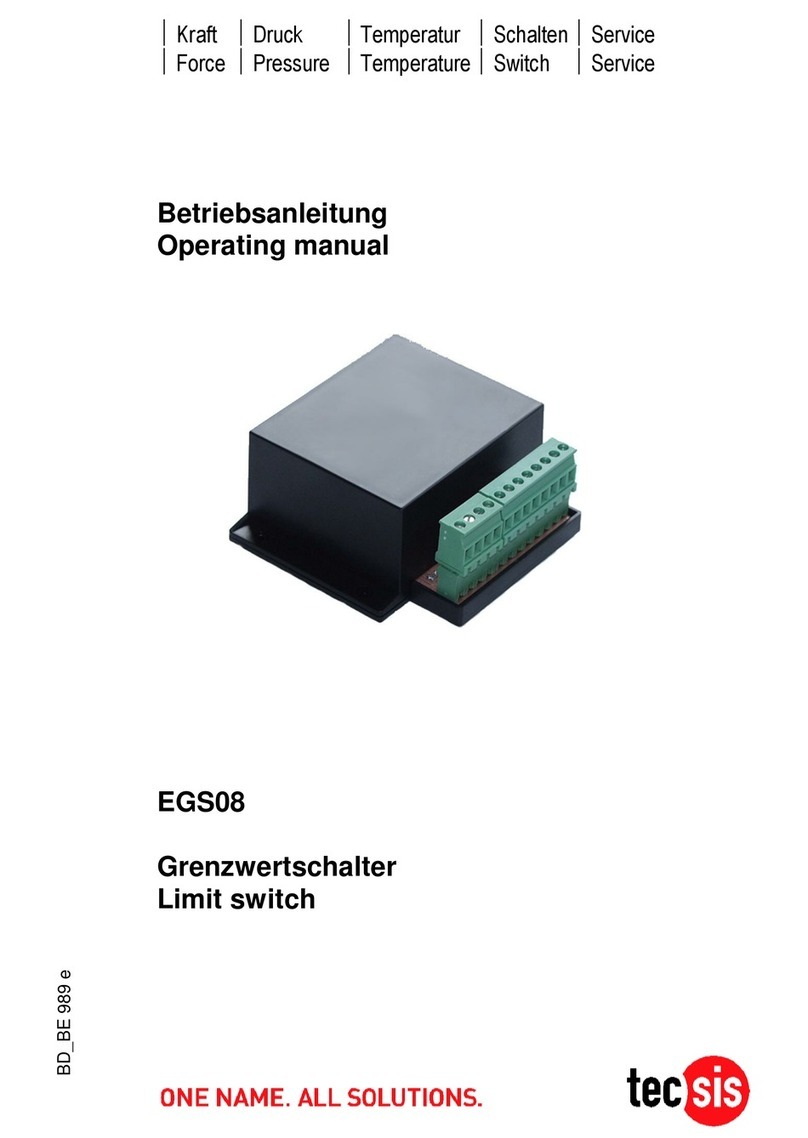
Tecsis
Tecsis EGS08 operating manual
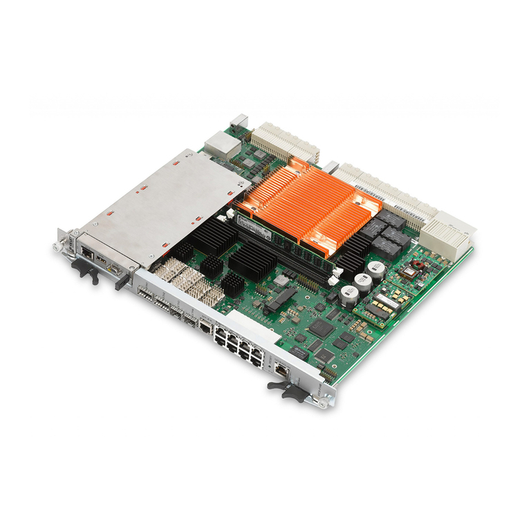
SMART Embedded Computing
SMART Embedded Computing ATCA-F140 Series Installation and use

Belkin
Belkin OmniView SOHO F1DD102L user manual
Advantech
Advantech EKI-2548I user manual

MSNswitch
MSNswitch UIS-322 user manual

Allied Telesis
Allied Telesis AT-FS709 installation guide
