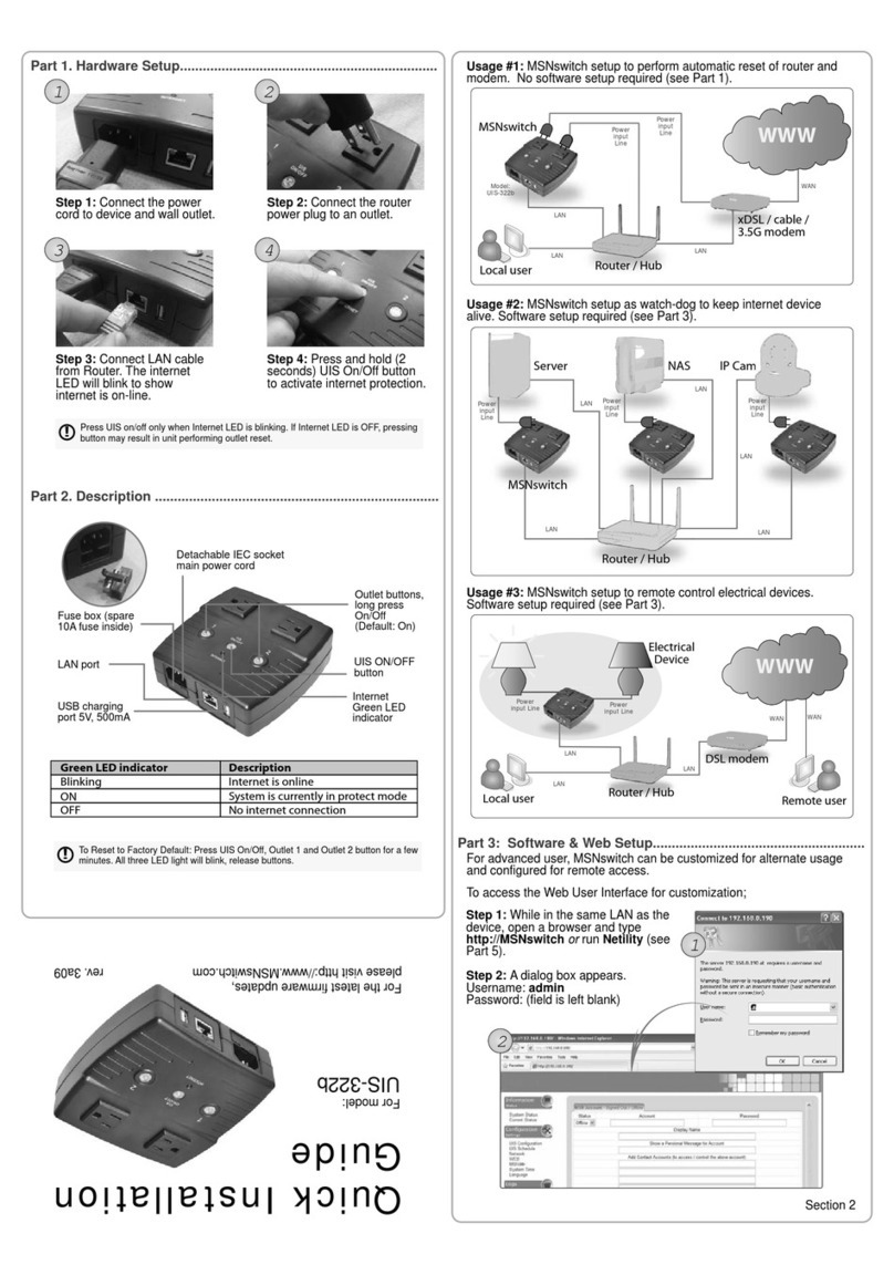
MSNswitch UIS-322 User manual

1
Remote Power Management Solution for Crashed Network Devices
USER MANUAL
Version: 2203 (MNT.NBU.7322 or higher)
!
!
!
!
!
!
!
!
!
!
!
!
!

2
!"#$%&'(&)'*+%*+,&
)-".+%/&01&2*+/'345+6'*777777777777777777777777777777777777777777777777777777777777777777777777777777777777777777 8!
1.1.##Introduction.................................................................................................................................................3#
1.2.#Hardware#Specification ................................................................................................................4#
1.3.##Network#Diagram......................................................................................................................................5#
1.4.##LED#Indicators#Explained ......................................................................................................................6#
)-".+%/&91&:"/3;"/%&<%+4. 777777777777777777777777777777777777777777777777777777777777777777777777777777777777 =!
)-".+%/&81&<'(+;"/%&>&?%#&<%+4.&@A'/&B3C"*5%3&D,%/E 77777777777777777777777777777777777777777 F!
3.1.##Introduction.................................................................................................................................................8#
3.2.##How#to#Locate#&#Access#IP#Switch#in#LAN ......................................................................................8#
3.2.1%%Locate%IP%Switch%in%LAN%using%Utility%program........................................................................ 9%
3.2.2%%Locate%IP%Switch%in%LAN%using%fixed%IP. ........................................................................................ 9%
3.3.##How#to#Access#IP#Switch#from#WAN#–#using#DDNS .................................................................11#
3.4.##How#to#Access#IP#Switch#from#WAN#-#using#Google#Talk/#Hangouts ..............................11#
3.4.1.%%How%to%Setup%Google%Talk/%Hangouts%for%the%IP%Switch ....................................................12%
3.5.#How#to#Access#IP#Switch#from#WAN#–#Using#Skype..................................................................14#
3.6.##How#to#Upgrade/#Re-Flash#Firmware...........................................................................................18#
)-".+%/&G1&2H&<;6+5-&?%#&D,%/&2*+%/("5% 77777777777777777777777777777777777777777777777777777777777777 9I!
4.1.##Information...............................................................................................................................................20#
4.2##Configuration ............................................................................................................................................21#
4.3##Log#Information .......................................................................................................................................34#
4.4##Help ...............................................................................................................................................................34#
)-".+%/&J1&!/'4#$%,-''+6*K&!6.,777777777777777777777777777777777777777777777777777777777777777777777777777 8=!
B..%*36L&B1&M'4+%/&)'*(6K4/"+6'*777777777777777777777777777777777777777777777777777777777777777777777777 GI!
B..%*36L&N1&2H&B33/%,,O&<4#*%+&"*3&P"+%;"Q 777777777777777777777777777777777777777777777777777777 G9!
B..%*36L&)1&P$',,"/Q 7777777777777777777777777777777777777777777777777777777777777777777777777777777777777777777 GG!
P''K$%&!"$R&9&<+%.&B4+-%*+65"+6'* 77777777777777777777777777777777777777777777777777777777777777777777777 GJ!

3
Chapter 1: Introduction
1.1. Introduction
IP Switch is designed to automatically power-cycle either one or both of its outlets
when either;
a) Internet connectivity is lost (resets Router/Modem to restart it), or
b) the network device being monitored is no longer responding in LAN.
It can also be used to:
a) remotely control outlets via instant messaging tool like Google Talk/ Hangouts, or
a Web User Interface.
b) perform scheduled power On / Off / Reset
c) manually control outlets by disabling the UIS (Uninterruptable Internet System)
function
IP Switch is useful where the Internet connection and accessibility to a remote site is
critical. It can be setup so that when the remote Mobile Broadband / Cable / Satellite
/ DSL / T1, etc. connection drops or if the remote router freezes-up, it will auto reset
the router to re-gain connectivity. IP Switch is also useful for:
1. Saving home users the trouble of constantly having to power-cycle their
router to re-gain Internet connectivity.
2. Resetting unresponsive device (for instance IP camera or NAS servers)
which otherwise will be inaccessible from remote.
3. IT Professionals who need to automatically or remotely reset devices
4. Preventing your connection from timing out or going dormant
5. Having devices on an automatic power schedule
Generalized description of network connection:
Hardware Specifications:
1. Built-in Web Server with 32-Bit RISC CPU.
2. 10/100Mbps Fast Ethernet Network Access.
3. Support IE or Java-Enabled Web Browser.

4
4. Network Protocol: HTTP, TCP/IP, UDP, SMTP, Dynamic DNS, DNS Client,
SNTP, DHCP.
5. Operating Temperature: 0°C ~ 60°C; Operating Humidity: 10% ~ 90%
6. For indoor use only.
1.2. Hardware Specification
Model No:
UIS-322
Socket type
2x of either;
a) Universal socket (Type X)
b) USA (Type B, NEMA 5-15R)
AUST / China (Type I, AS / NZS3112, CCC)
Certifications
CE, FCC (tested to be compliant with FCC 47 CFR Part 2 and Part
15 Class B equipment regulations)
Electrical Rating
Input: 125~250V~50/60Hz
Output: 10A (for 2 sockets) & DC5V, 500mA (for USB port)
Breaker
10A (Thermal fuse)
Available Sockets
2x fixed
Internet Control-able
2x fixed socket
Power ON / OFF switch
Individual outlet power ON / OFF LED button
(Press & hold 2 seconds)
Power Indicator
Orange LED
Reset to Factory Default
Reset button located to the right of Ethernet port
Internet Indicator
Green LED
Web Server CPU
32-Bit RISC CPU
Supported browser
IE and Java
Supported Network
Protocols
HTTP, TCP/IP, UDP, SMTP, Dynamic DNS, DNS Client, SNTP,
BOOTP, DHCP.
Network Access
10/100 Base-T, RJ45 (Cat. 5)
Operating Environment
0°C to 60°C at 10% to 90% relative humidity.
For indoor use only.
Package
White Box

5
1.3. Network Diagram
The following Network diagrams applies to all IP Switch models.
Fig.1 IP Switch setup to perform auto reset of router and modem
Fig.2 IP Switch setup to keep Internet device alive.

6
Fig.3 IP Switch setup for remote control via Google Talk/ Hangouts or thru Web User
Interface.
1.4. LED Indicators Explained
LED Status for Internet & Outlets
LED
LED status
Condition description
Internet
Solid Green
Internet connection available and UIS (Uninterruptable
Internet System) mode has been activated.
Internet
Blinking Green
There is internet connection. UIS mode button has not
been activated. With UIS enabled however, this means
that at least one of the target sites is not responsive
(regardless of being assigned or not)
Internet
OFF
There is no internet connection.
Outlet
Solid Orange
Outlet is powered ON
Outlet
OFF
Outlet is powered OFF
Fig.4 LED Indicator
LED Status on LAN Port
Light color
Condition description
Green
When On: Internet speed is at 100M
When flashing: Data transmitting / receiving
Yellow
On: Internet correspond speed is 10M
Flash: Data transmitting / receiving

7
Fig.5 LAN LED Indicators
Fig.6 Description
Chapter 2: Hardware Setup
IP Switch hardware installation procedure:
Step 1:
Connect the power cord to device and wall
outlet. The two orange LED will light up,
indicating that the individual Outlet is ON.
Press the Orange LED for 2 seconds to
turn the Outlet On / Off.
Step 2:
Connect the power plug to IP Switch
outlet.
NOTE: In order for IP Switch to
maintain continuous Internet
connection or reset your modem/
router, the router power input must
be connected here.

8
Step 3:
Connect LAN cable from your router.
Step 4:
Make sure the Internet LED light is
blinking to show that the internet
connection is ready.
Press and hold the “UIS On/Off” button
(about 2 seconds) to activate internet
protection, which will allow the switch to
auto reset upon loss of connection to the
Target sites (i.e web site addresses or
local IP addresses). This completes the
basic setup.
Chapter 3: Software & Web Setup (For Advanced User)
3.1. Introduction
IP Switch is designed to work without having to install any software (see hardware
setup above). However, for the advanced user, the unit can be customized and
configured for remote access. This gives the user further control over the power
ports.
There are two ways to remotely control the outlets (access from WAN);
a. Using DDNS and Port forwarding, see Section 3.3 or;
b. Using Google Talk/ Hangouts instant messaging tool, see Section 3.4.
3.2. How to Locate & Access IP Switch in LAN
IP Switch comes with a built-in Web User Interface (Web UI) that allows for more
advanced control over the unit. There are two ways of accessing the Web UI in LAN
(i.e. when both IP Switch and PC is connected to the same router).
1. Utility program (available for Windows only)
2. Use a fixed IP (when there’s no DHCP server).
*Note–You can also use any LAN program to locate the WebUI URL for example:
Mac: LANscan https://itunes.apple.com/us/app/lanscan/id472226235?mt=12
Windows: Wireshark or Angry IP Scanner

9
3.2.1 Locate IP Switch in LAN using Utility program.
Step 1:
Download the Utility program from
http://3gstore.com/ipswitchupdates and
install.
Once installed Utility will locate and list the
IP Switch units.
NOTE: Utility can only discover the IP
Switch units that are located within the
same LAN or network. Be aware that
certain things such as VPN, antivirus,
admin privileges, etc, can prevent
Utility from locating your device(s).
Utility will show LAN IP if units are
connected to a Router. If you are
connecting to your computer directly,
you will need to manually assign an IP
address to the device via the ‘Network’
tab, as well as manually set an IP for
your computer’s Ethernet adapter.
Step 2:
Click “Launch Web User Interface” to run
Internet Explorer (or your default browser)
and access the IP address of the unit.
A password dialog box will appear.
By default; Username/ password is:
admin/ admin. Press “OK” to proceed.
Step 3:
You will be logged into the IP Switch.
3.2.2 Locate IP Switch in LAN using fixed IP.
By default, the IP Switch should obtain an IP address automatically from your router
using DHCP. If for some reason it does not, press and hold the UIS button for 10
seconds and it will revert to a fixed LAN IP of 192.168.0.100.
To access IP Switch Web interface in this mode:

10
Step 1:
Connect the LAN cable from IP Switch to your PC’s Ethernet port
Step 2:
Assign a fixed IP within the same subnet to your PC. Example: IP address -
192.168.0.20; Subnet Mask - 255.255.255.0; Gateway: 192.168.0.1
Step 3:
On your PC, launch a web browser and enter the IP: 192.168.0.100 - Login
username/ password: admin/ admin. You can now change this fixed IP address
to one that you prefer by going to Configuration Settings -> Network.

11
3.3. How to Access IP Switch from WAN –using DDNS
The IP Switch Web User Interface (Web UI) can be accessed remotely from Wide
Area Network (WAN). To do so, you must have a public dynamic IP address from
your ISP (Internet Service Provider) -if you’re unsure about this, please contact your
ISP. Once you’ve confirmed that, proceed as follows;
i. Setup port forwarding at your router.
a. Log into your router setup / configuration page.
b. Most routers will have these settings under the Firewall / Port
Forwarding / Virtual server section. You will need to open (allow):
WAN Port 80; Type/Protocol: TCP. (NOTE: You may need to forward
port 80 to a different port if you have other devices on the netowrk using
that port)
and,
ii. Setup a Domain Name for your Dynamic WAN IP. Use 3rd Party DDNS
providers. To do so;
a. The following 3rd party DDNS providers below are supported;
• 3322.org
• DynDNS (Dynamic)
• DynDNS (Custom)
• myDDNS.com
• No-IP
b. Create a new user account and password.
c. Register a Domain Name for your current Dynamic WAN IP.
d. Log into your outlet via its local IP Address and navigate to →
Configuration Settings →Network →Dynamic DNS. Select
the service provider; enter the registered domain name, user
account, and password. Click Apply.
The IP Switch is now accessible remotely using the newly registered Domain Name.
For a description of Network →Dynamic DNS functions see section 4.2.3.
3.4. How to Access IP Switch from WAN -using Google Talk/
Hangouts
IP Switch supports Google Talk/ Hangouts, an instant messaging tool. Once setup,
user can get notifications and issue commands to check the status, as well as turn
on/off power or power-cycle certain ports using Google Talk/ Hangouts.
Before starting, you will need firmware version MNT.NBU.5326,
2.40.MNS.NBU.6311, or newer, as well as 2 Gmail accounts - 1 designated as the
IP Switch & 1 as the Control account.

12
3.4.1. How to Setup Google Talk/ Hangouts for the IP Switch
Step 1:
From the Utility application, select
‘Launch Web User Interface’ -
when prompted, log in with the
default user name & password:
User Name: admin
Password: admin
NOTE: If Utility cannot locate your
Switch, please refer back to
section 3.2.1
Step 2:
Below the ‘Configuration Settings’
button on the left, select ‘Google
Talk’ or ‘Hangouts’ (depending on
your firmware version)
a. Towards the top left corner you’ll
notice ‘Status’ - by default this is
set to ‘Offline’ - You will need to
change this to ‘Online’
b. For the ‘Login ID’ enter the Gmail
Account associated for the Switch
(Example: IPswitch@gmail.com).
c. Now, enter the Password for the
same Gmail account in the
‘Password Field’
d. Under the ‘Add Contact
Accounts’ enter your control Gmail
account that will be used to control
the switch (Example:
e. Click ‘Apply’
Step 3:
Allow a few moments for IP Switch
to connect and Sign in. The
connection status will be shown on
the heading.

13
Step 4:
Once connected, you’ll want to log
into your control Gmail account. The
users listed in your Contact List will
receive a notification to add the IP
Switch as a ‘contact’.
Once added, you can control the IP
Switch by chatting with it.
NOTE 1: If you do not receive an ‘invite’ notification, you may need to
log into your IP Switch’s Gmail account to ADD CONTACTS directly from
there.
NOTE 2: Only the users listed in the CONTACT ACCOUNT section can
command IP Switch. If you are removed from this list, you will still be on
the IP Switch’s contact list within the Gmail account, but you will be
unable to send commands to it.
NOTE 3: If you are using Google 2-step authentication, see page 45 for
configuration steps.
3.4.2. How to Control IP Switch using Google Talk/ Hangouts
After setting up and getting connected as
above. Bring up the IP Switch chat
window by inviting it to chat.
*Typing in anything other than the
Keywords will invoke IP Switch to
respond with “Please type HELP to list
available commands.”
Available commands are (non case
sensitive):
SET [ON/OFF/RESET] [0/1/2](where
0=both outlets, 1/2=Outlets)
UIS [ON/OFF]
GET [IP/STATUS]

14
SET ON / OFF / RESET command will
return a “Done!” once IP Switch has
completed the action.
GET IP command will return the WAN IP
and the unit’s LAN IP address.
*If port forwarding is set, but not the
domain name, user can still use WAN IP
to access the IP Switch Web User
Interface from internet.
GET STATUS command will return the
following information.
For [Outlet Status] the Outlet1 and
Outlet2 name can be assigned. This is
done via the local IP address of the IP
Switch ...→Configuration →
Configuration →Outlet Setup.
*Allow time for the system to respond.
*NOTE: There is also a mobile
application called “Hangouts” that can
be used in this same manner. It is
available for Android and iOS.
3.5. How to Access IP Switch from WAN –Using Skype
As an alternative to the Google Talk/ Hangouts, you can now use Skype to
monitor and control your outlets.
Step 1: While connected to the same network as the 3Gstore IP Switch, open
a browser and enter this address: http://outlet (*only works on windows OS)
otherwise use the IP Address to the switch i.e. 192.168.0.197 or try using the
Utility program ( *Windows only Program)
Step 2: Admin Screen
1. Select Save/Upgrade on the left hand side of the screen
2. In the Upgrade Firmware Section under Location Select Choose File
3. Locate the File you downloaded (usually under downloads)
4. Click Open
5. Click Apply
6. Uploading Firmware will prompt for a couple of minutes

15
Step 3: Initiate Skype:
1. Under Configuration Settings Select Skype
2. In the Skype Function Section Click on Enable
3. Then Click on Auto Rebooter (a separate tab will open see Step 4)
3. Click Apply
Step 4: Auto Rebooter
1. Click Add to Contacts

16
Step 5: Open The Skype App
1. Under the Contacts Section select Auto Rebooter
2. Type Help
3. Click Get My ID
4. Copy and Paste the ID

17
5. Toggle back to the Admin Screen
6. Enter the Name for your Switch (any name you want to represent)
7. Paste the ID in the ID field
8. Click Add
Step 6: Skype Control
1. Switch back to the Skype App
2. Click on Help then Show My Devices
3. Select the button that corresponds to the action you wish to perform
4. Example Status
5. Status will be displayed
Command example

18
Result
Other Commands:
Outlet 1 or 2
Turn ON
Turn OFF
Reset
Back
UIS
Turn ON
Turn OFF
Back
Note*
If you have multiple outlets, just use the same ID (from Get My ID)
3.6. How to Upgrade/ Re-Flash Firmware
When issues occur with your IP switch, it is best to upgrade firmware (if available) or
re-flash the current version of firmware. This can be done with the Utility application
OR via the local web interface page. It can be accomplished with a computer that is
connected to the same network as the IP switch or, in certain cases when the IP
Switch is unreachable, you may connect it directly to your computer via the Ethernet
cable.
NOTE: Before performing the upgrade, it is recommended that your save your
settings. See section 4.4.1 for instructions on the Save/ Restore settings info.

19
Upgrade Using Utility
Step 1: Launch the ‘Utility’ Windows
Application and let it detect IP switch.
Step 2: Click on the ‘Firmware
Upgrade’ button.
NOTE: If Utility cannot locate your
Switch please refer back to section
3.2.1
Step 3: In the dialog box that opens,
select the ‘…’button to the right of
‘File Name.’
Step 4: Locate the firmware file and
open it.
Step 5: The file name should now
appear in the appropriate field. Now,
select the ‘Download’ button
Upgrade Using Local Web
Interface
Step 1: Log into the web user
interface of your IP Switch
Step 2: Navigate to the
Save/Upgrade section (on the left)
Step 3: Under the 'Upgrade
Firmware' section, click on the
'Browse'/ 'Choose File' button
beside 'Location'
Step 4: A window will open to view
your computer files. The firmware
typically saves to your downloads

20
folder. Select the .bin file named and
click Open
Step 5: You'll now see the file appear
next to 'Location’ -> Click Apply to
begin the upgrade
NOTE: The firmware process takes
about 2-5 minutes.
Chapter 4: IP Switch Web User Interface
4.1. Information
The Information tab contains the following subsections:
4.1.1 Current Status
This section displays the current status of the outlets.
Table of contents
Other MSNswitch Switch manuals
Popular Switch manuals by other brands

ADC
ADC FireWire Patch Panel IEEE 1394a Specification sheet

Edimax
Edimax EK-UA2C user manual

SICK
SICK ES21 M12 contact operating instructions

KROHNE
KROHNE OPTISWITCH 5100 C Handbook

Phoenix Contact
Phoenix Contact FL SWITCH SMCS 8TX Installation notes for electricians

Mallory
Mallory 646 installation instructions