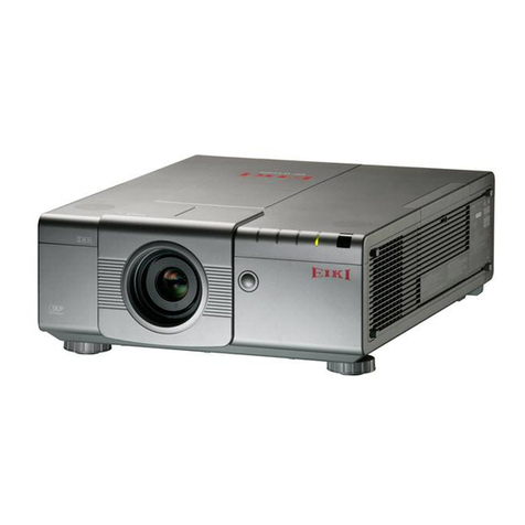
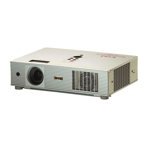
Eiki EIP-UJT100 User manual

1 of 73
PROJECTOR
Service Manual
EIP-UJT100
Rev.00

2 of 73
DLP DIGITAL PROJECTOR rev.00
Revision
Description
Date
Rev.00
Preliminary
5/13/2015

3 of 73
CONTENTS
1,COMPLIANCE OF SAFE REPAIR..........................................................................4
1-1 Cautions during disassembling and assembling……………………….…………….4
1-2 Lamp………………………………………………..……………….………….…………… 4
1-3 Lens………………………………………...………..………………………….…………….4
2. SPECIFICATIONS ..............................................................................................5
2-1 Optical Specifications…………….….……………………………………..…………….5
2-2 Block Diagram…………………………….….…………………………………………….6
2-3 Fan Location. ...........................................................................................................7
3. TROUBLESHOOTING.........................................................................................9
3-1 Control Keys and LED Indicators………………………………………….………..…..9
3-2 RS-232 Settings…………………..……………………………………………………….10
4. KEY PART REPLACEMENT & WIRE DRESSING…...……………………….…………...…19
5. ADJUSTING……………..…………………………….…………..…….…..….…...…51
5-1 Folding Mirror Adjusting..………..………………………….…………………………..51
5-2 Focus Adjusting…..………………..………………………….…………………………..52
6. MAINTENANCE………………………..…………………………………………..…………..….57
6-1 Cleaning the projector………………………………….….…….……………………....57
6-1-1 Cleaning the cabinet.….………………….……….…………..….…….......57
6-1-2 Cleaning the Lens.……...……….……….…….……..……….….…….......57
6-1-3 Replace the filters.…………..………….….….…….…….…………….…..57
6-1-4 Cleaning the optical parts………………….….….…………….……..……58
6-2 Replacing Consumable Parts………………………….….…….……….…………..….59
6-3 Replacing the Lamp……….…………………………….….…….……….………….…..60
6-4 Replacing the Filter……….….………………………….….…….……………………....63
7. SPART PARTS LIST & SPARE PARTS PHOTO………..…………………………..……..…65
APPENDIX TIMING TABLE………………………………………………….…….….………...…71

4 of 73
1. COMPLIANCE OF SAFE REPAIR
Be sure to read this Service Manual before providing services.
In the projector, full consideration is taken to ensure the safety for fire, electric shock, injury, harmful radiation,
and substance. Therefore, observe the notice described in this Service Manual so that safety is kept when
providing services. Moreover, be sure to observe the notice described in the Instruction Manual.
Pay attention to the following during service inspection.
1-1 Cautions during disassembling and assembling
1. This equipment contains parts under high voltage. When making repairs, etc. Be sure to pull out the power
plug beforehand to insure safety.
2. Parts may be very hot immediately after use. Make sure the equipment has cooled off sufficiently before
carrying out repairs.
3. Make sure that parts and screws and wiring, etc. are returned to their original positions. Tube, tape and
other insulation materials have been used for safety reasons. The internal wiring has been designed to
avoid direct contact with hot parts or parts under high voltage when using clamps or other tools.
4. The parts used in this device have special safety features such as flame-resistance and anti-voltage
properties. When replacing parts, always use parts supplied from the factory.
5. After finishing operations make sure that all parts and wires have been returned to their original position and
that there has been no deterioration of the area around the location that was worked on.
6. Be sure to use an earth band (wrist band) during repair and inspection.
1-2 Lamp
During current conduction, the lamp is in the high-temperature state. In this case, pay careful attention
because a high voltage is used. When replacing a lamp, replace it after confirming that the lamp has cooled
sufficiently.
1-3 Lens
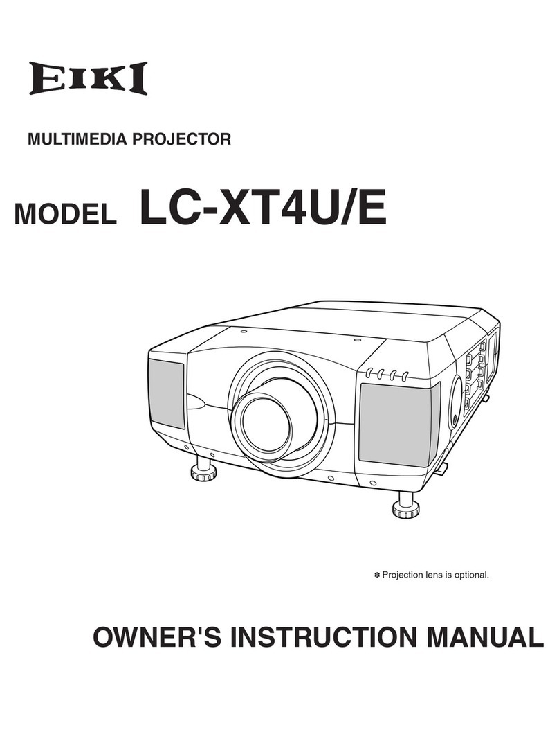
Do not look into the lens during projection. This damages your eyes.
5 of 73
2. SPECIFICATIONS
This section provides technical information about the projector's performance.
2-1 Specifications

6 of 73
2-2 Block Diagram
EIP-UJT100 ALL Boards' Function Block Diagram

7 of 73
2-3 Fan Location
Fan. No
Connector
TYPE
Function
Normal
Eco
FAN0
FANS E BD(CN635)
3PIN
AFB0612HC-F00
RDMD cooling
3500 RPM
2900 RPM
FAN1
FANS E BD(CN635)
4PIN
AFB1212H-SM09
Exhaust
2000 RPM
1500 RPM
FAN2
FANS E BD(CN635)
5PIN
AFB1212H-SM09
Exhaust
1800 RPM
1500 RPM
FAN3
FANS E BD(CN635)
6PIN
AFB1212H-SM09
Exhaust
1800 RPM
1500 RPM
FAN4
FANS B BD(CN636)
3PIN
BFB1212L-SZ57
Prism cooling
1200 RPM
900 RPM
FAN5
FANS B BD(CN636)
4PIN
BFB1212L-SZ57
Engine flow inlet
1200 RPM
900 RPM
FAN6
FANS B BD(CN636)
5PIN
AFB0812HD-AF00
GDMD cooling
2300 RPM
2000 RPM
FAN7
FANS B BD(CN636)
6PIN
BFB0612HB-SE13
RDMD front cooling
2500 RPM
2500 RPM
FAN8
FANS C BD(CN637)
3PIN
AFB1212H-SM09
Power/ballast cooling
2200 RPM
1200 RPM
FAN9
FANS C BD(CN637)
4PIN
AFB1212H-SM09
Power/ballast cooling
2200 RPM
1200 RPM
FAN10
FANS C BD(CN637)
5PIN
AFB0812HD-AF00
BDMD cooling
3500 RPM
2000 RPM
FAN11
FANS C BD(CN637)
6PIN
BFB0612HB-SE13
BDMD front cooling
3500 RPM
2500 RPM
FAN12
FANS D BD(CN638)
3PIN
BFB0712HD-SE04
Prism cooling
2800 RPM
2400 RPM
FAN20
CN646(PWM)OnBoard
4PIN
BFB0712HD-SP01
Lamp burner
4400 RPM
2800 RPM
FAN21
CN647(PWM)OnBoard
5PIN
BFB0712HD-SP01
Lamp burner
3300 RPM
2000 RPM
FAN22
CN648(PWM)OnBoard
6PIN
BFB0712HD-SP01
Lamp burner
3800 RPM
2500 RPM
FAN23
CN649(PWM)OnBoard
7PIN
BFB0712HD-SP01
Lamp burner
2800 RPM
1800 RPM
FAN-R1
Main Formatter BD (CN4)
3PIN
BFB0712LD-SE00
FPGA cooling
2800 RPM
2800 RPM

8 of 73

9 of 73
3. TROUBLESHOOTING
3-1. Control Keys and LED Indicators

10 of 73
3-2. RS-232 Settings
Interface and Requirements
The RS-232 Commands use only ASCII characters which can be entered
using a typical terminal emulator like Windows HyperTerminal with
the following setting:
Bits per second: 19200 (Delta Mode: 115200)
Data bits: 8
Parity: None
Stop bits: 1
Flow control: None
Note that each input character will be echoed on the terminal by MCU and
there is no need to set the local echo “ON” with the terminal setting.
When using “Delta Mode”to operate projector, please use
baud rate “115200”to set and communicate.
When using “Normal Mode”to operate projector, please
use baud rate “19200”to set and communicate.

11 of 73
A. Use RS-232 comment to Retrieve Error Code
Step0. A. Connect the AC power of the projector and have the projector in standby mode.
Step1. A. Connect the RS-232 cable between the projector and the PC.
B. Open a terminal program (e.g. Tera Term) with the following setting, baud rate 115200,
Databit: 8, Parity: none, Stop: 1bit, Flow control: none.
C. Press keypad “Menu”+“Input” (for 3 seconds). And, RS-232 mode systems will feedback
“Delta Mode”.

12 of 73
If terminal show “Delta Mode”, it is entry Delta UART Mode
D. Please key in “op prerr”, and then it will show all accumulated history error codes.
And, the first error code will be the current root cause of defective symptom. Then, please
go to error code list to contrast to actual root cause.

13 of 73
E. After getting and confirm the error code from RS-232 tera term systems, please select
“File”, and then go to select “Exit”.
And, the RS-232 tera term system will be closed and exit.
F. After exit the RS-232 tera term system, please turn off the projector. And, then turn on the
projector again. The projector will go back to the normal mode.

14 of 73
B. Use the RJ-45 comment to Retrieve Error Code
A. Connect theAC power of the projector and have the projector in standby mode.
B. Connect the RJ-45 cable between the projector and the PC. And make sure that the two LEDs
of the RJ-45 module are lit after connecting the RJ-45 cable between the PC and the projector.
If the LEDs are not lit, please send the RS command “eco.net.pow = 0” on the terminal to turn
on the RJ-45 module.
C. Properly setup the IP for the PC and make sure that the PC and the projector are in the same
subnet. For example, the default IP of the projector is 192.168.0.100. So the IP of the PC
should be set as 192.168.0.99 for example.
D. Key in the projector IP on the web browser (the recommended web browser is IE 6.0 or later
version, the default IP is 192.168.0.100) to see the embedded webpage. The IP can be
accessed via the RS command “op net.ipaddr ?” with a terminal program.

15 of 73
When you get the Web interface, please select “Advanced Diagnostics”to get “error code”.
They are defined as below table.

16 of 73
Error Code Message –Troubleshooting and what parts need to replace
0
ErrMsgOverTempInlet: –Temp. is over spec. Check if there is anything
blocks in inlet or replace Inlet thermal sensor.
1
ErrMsgOverTempDMD –Temp. is over spec. Check or replace DMD thermal
sensor.
2
ErrMsgOverTempLamp1–Check or replace Lamp 1 thermal sensor state.
3
ErrMsgOverTempLamp2–Check or replace Lamp 2 thermal sensor state.
4
ErrMsgOverTempBallast1–Check and replace Ballast1 thermal state.
5
ErrMsgOverTempBallast2 –Check and replace Ballast2 thermal state.
6
ErrMsgFanInitError–Anyone fan could be error when power on. Thus, check
and replace error fan you find out. And, try to replace fan board.
7
ErrMsgFan0RotateError –Fan0 gets error during projector working. Check
and replace fan 0.
8
ErrMsgFan1RotateError –Fan1 gets error during projector working. Check
and replace fan 1.
9
ErrMsgFan2RotateError –Fan2 gets error during projector working. Check
and replace fan 2.
10
ErrMsgFan3RotateError –Fan3 gets error during projector working. Check
and replace fan 3.
11
ErrMsgFan4RotateError –Fan4 gets error during projector working. Check
and replace fan 4.
12
ErrMsgFan5RotateError –Fan5 gets error during projector working. Check
and replace fan 5.
13
ErrMsgFan6RotateError –Fan6 gets error during projector working. Check
and replace fan 6.
14
ErrMsgFan7RotateError –Fan7 gets error during projector working. Check and
replace fan 7.
15
ErrMsgDMDInitFail –Check and replace main formatter board, formatter
board and DMD chip.
16
ErrMsgLampInitFail –Check and replace ballast 1.
17
ErrMsgLampLitFail –Check and replace Lamp 1.
18
ErrMsgBallastUartError –Check and replace ballast 1 and power board.
19
ErrMsgExGpioFail –Check and replace video or uc control board.
20
ErrMsgInterLockOpen–Check and confirm Interlock.
21
ErrMsgGF9450NoResponse –Check and replace video board.

17 of 73
22
ErrMsgSystemI2cFail –Check and replace all board.
23
ErrMsgSoftwareI2cFail –Check and replace all board.
24
ErrMsgEepromFail –Check and replace uc control board.
25
ErrMsgEdidFail–Check and replace video board.
26
ErrMsgEepVersionFail–Check and replace video board.
27
ErrMsgRstGennum –Check and replace video board.
28
ErrMsgFan8RotateError –Fan8 gets error during projector working. Check and
replace fan 8.
29
ErrMsgFan9RotateError –Fan9 gets error during projector working. Check and
replace fan 9.
30
ErrMsgFan10RotateError –Fan10 gets error during projector working. Check
and replace fan 10.
31
ErrMsgFan11RotateError –Fan11 gets error during projector working. Check
and replace fan 11.
32
ErrMsgLamp2LitFail ––Check and replace Lamp 2.
33
ErrMsgBallast2UartError ––Check and replace ballast 2 and power board.
34
ErrMsgGtInletTp ––Check or replace Inlet thermal sensor.
35
ErrMsgGtDmdTp –Check or replace DMD thermal sensor.
36
ErrMsgInletTempSensorFail––Reserved &None for this model.
37
ErrMsgDMDTempSensorFail –Reserved &None for this model.
38
ErrMsgGeoSystemFail –Check and replace the W2 board.
39
ErrMsgNormal ––Reserved &None for this model.
40
ErrMsgFan12RotateError ––Fan12 gets error during projector working. Check
and replace fan 12.
41
ErrMsgFan13RotateError –– Reserved &None for this model.
42
ErrMsgFan14RotateError –– Reserved &None for this model.
43
ErrMsgFan15RotateError –– Reserved &None for this model.
44
ErrMsgFan16RotateError –– Reserved &None for this model.
45
ErrMsgFan17RotateError –– Reserved &None for this model.
46
ErrMsgFan18RotateError –– Reserved &None for this model.
47
ErrMsgFan19RotateError –– Reserved &None for this model.
48
ErrMsgFan20RotateError ––Fan20 gets error during projector working. Check
and replace fan 20.
49
ErrMsgFan21RotateError ––Fan21 gets error during projector working. Check
and replace fan 21.
50
ErrMsgFan22RotateError –Fan22 gets error during projector working. Check
and replace fan 22.

18 of 73
51
ErrMsgFan23RotateError –Fan23 gets error during projector working. Check
and replace fan 23.
52
ErrMsgFanR1RotateError –FanR1 gets error during projector working. Check
and replace fan R1.

19 of 73
4. KEY PART REPLACEMENT & WIRE DRESSING
Service Tool of disassembly whole projector as below:
Inner Hexagon
Screwdriver
5mm
Inner Hexagon
Screwdriver
14mm
Normal
Cross Type
Screwdriver
6mm

20 of 73
4-1 Top Cover
Put the projector on the table.
Take out the sponge from the
projector. And, loosen 1 screw on the
front cover. (Torque: 70~80 Nm)
Loosen 3 screws on the back of top cover.
(Torque: 70~80 Nm)
Open the top cover.
Other manuals for EIP-UJT100
2
Table of contents
Other Eiki Projector manuals

Eiki
Eiki LC-WB40N User manual

Eiki
Eiki Multimedia Projector LC-XG400 User manual

Eiki
Eiki EIP-4500 User manual

Eiki
Eiki LC-XM1 User manual

Eiki
Eiki LC-5000U Setup guide

Eiki
Eiki ESL Series User manual

Eiki
Eiki LC-NB3S User manual

Eiki
Eiki LC-XT6 User manual

Eiki
Eiki EK-100 series User manual

Eiki
Eiki EIP-25 Setup guide