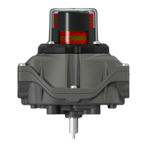
Eisenbau GuaRdboX GD Series Instruction manual

GuaRdboX
-
G
d
series
IOM (
Installation, Operation & Maintenance Manual) 0100-ENG
rev.5
1
Eisenbau s.r.l. a socio unico
Via T.A:Edison, 16 20090 Cusago (MI) Italy
Phone : +390293562116 Fax: +390293567735
Guardbox production unit : Via XXIV Maggio, 13
25017 –Sedena di Lonato (BS)
Phone : +390309131240 Fax: +390309130946
www.eisenbau.it
www.
guardbox
-
ex.com
1. Introduction:
This instruction manual contains important information regarding the safety instructions, installation, operation, maintenance and storage of
the “Guardbox”limit switch boxes.
The limit switch boxes may only be mounted, wired and installed by qualified and trained personnel, according to International standards
requirements for hazardous areas. If you require any additional information or assistance, please contact the manufacturer or its
representative. All contacts are listed in the footnote together with the QR code for an easy access to the complete product documentation.
Please read these instructions carefully before proceeding with the limit switch box installation and save them for future reference.
2. Product description:
Guardbox Limit switch boxes are electromechanical devices ideal for monitoring the remote operation of industrial valves in plants,
designed and manufactured for demanding application in extreme environments and where there are requested high standards for safety
and reliability products. The Guardbox devices are used to control the position of the valve and provide high accuracy electrical feedback
signal of valve status to plant control systems. Guardbox devices are equipped in standard configuration with a 3D high visibility position
indicator that represent a true indication of valve position. The indicator is visible on all 4 sides and is fully adjustable on 360° without
disassembly. Guardbox limit switch boxes are built to be installed on valves or actuators which drive the process valves from closed to
open position (Normal acting) or from open to closed position (Reverse acting) . Normal acting is considered full CW when the process
valve is closed and CCW when the process valve is open. Reverse acting is full CW when the process valve is open and CCW when the
process valve is closed.
3. Safety instructions:
Guardbox Limit switch boxes are electromechanical devices ideal for monitoring the remote operation of industrial valves in plants,
designed and manufactured for demanding application in extreme environments and where there are requested high standards for safety
and reliability products. The Guardbox devices are used to control the position of the valve and provide high accuracy electrical feedback
signal of valve status to plant control systems. GD Guardbox explosion proof Exd series limit switch box are specially projected and built to
withstand the most extreme weather conditions and be installed into hazardous areas with flammable gases, vapours and mist, according
with the relevant Union harmonization legislation of ATEX Directive 2014/34/EU, and to IECEx Scheme and applicable standards.
Reference standards are the IEC60079-0:2011 (Ed6.0), IEC60079-1:2014 and IEC60079-31:2013 (Ed2.0), and the applied marking of
Group, category and applied Ex protectionis:
Ex –Equipment Marking II2G Ex db IIC T6…T4 Gb
II2D Ex tb IIIC T85°C…T135°C Db
Ex –Marks
II 2 G Ex db IIC T6 T5 T4 Gb
II 2 D Ex tb IIIC T85°C T100°C T135°C Db
On the outside of the Exd box cover there are two metal nameplates on which are etched and marked the Ex-marking and all the
information and references about the manufacturer, electrical and ambient range of use of the specific product, together with a Data Matrix
code for a quick link and easy access to the product documentation including wiring diagram, drawings, datasheet and certificates:
group
category
Dust
-
flammable
-
gas
Protection
concept
Dust group
Gas group
Tempera
ture
class
Max surface
temperature
Dust
-
flammable
-
gas
Ex
-
Symbol

GuaRdboX
-
G
d
series
IOM (
Installation, Operation & Maintenance Manual) 0100-ENG
rev.5
2
Eisenbau s.r.l. a socio unico
Via T.A:Edison, 16 20090 Cusago (MI) Italy
Phone : +390293562116 Fax: +390293567735
Guardbox production unit : Via XXIV Maggio, 13
25017 –Sedena di Lonato (BS)
Phone : +390309131240 Fax: +390309130946
www.eisenbau.it
www.
guardbox
-
ex.com
Ex –Equipment Marking
The certification relies upon the following materials used in its construction: Box housing made up of body and cover is in Stainless Steel
AISI316L, or Aluminium Alloy EN AB ed AC 44300 Al Si 12 (Fe) (a). In order to comply with the requirements for the equipment protection
level (EPL), the material of the enclosure must be chosen as follow:
Table 1 –Relation between EPL and type of material of the enclosure
EPL
(explosion protection level)
Enclosure material
Gb / Gc Aluminium Alloy EN AB ed AC 44300 Al Si 12 (Fe) (a) or Stainless steel 316L (CF3M)
Box gasket is in silicone rubber. It is the responsibility of the user to ensure that all the following safety instructions, essential health and
safety requirements and warnings are observed during installation, operation and maintenance of the product:
3.1 These instructions must carefully read before proceeding with the limit switch box installation and saved for future reference.
3.2 Installation should be carried out by suitably trained personnel to an applicable Code of Practice (eg IEC/EN60079-14 &
IEC/EN61241-14).
3.3 If the box is integrated in a system or in a plant, the customer shall ensure that the local safety regulations are observed.
3.4 Before proceeding with the wiring, make sure that the characteristics of the electrical connection are compatible with electrical
operation parameters of operation of the box.
3.5 Do not exceed the limit switch box performance limitation. Exceeding the limitation may cause damage to the limit switch,
actuator and valve.
3.6 Where the temperature under rated conditions is higher than 70°C at the entry point or 80°C at the branching point of the
conductors, use field wiring suitable
to work at minimum and maximum ambient operating temperature indicated on the
external nameplate of the box.
3.7 Operating the box over temperature limits will damage internal and external components.
3.8
RISK OF SEVERE INJURIES!: Do not open the box when energized or in presence of explosive atmospheres.
3.9 Guardbox products are supplied with plastic caps fitted on the customer requested cable entries. Task of these caps is to
protect the internal circuits of the products in the time between manufacturing and commissioning. It is responsibility of the
installing personnel to replace the protective caps with suitably certified and temperature rated cable glands and blanking
plugs permitted for use with ATEX/IECEx flameproof enclosures.
3.10 Product IP rating is ensured only by the use of suitable IP rated cable glands and plugs.
3.11 All cable entry devices shall be certified in type of explosion protection ‘d’and suitable for the area classification in accordance
with the National Electrical Code.
3.12 Any unused cable entries must be sealed with suitably certified stopping plugs.
ExNB acronyms
and certificate
number
Manufacturer
contacts
Marking of group,
category and
applied protection
concept
Symbol of
explosion
protection
Conformity
symbol
Warning
markings
IP
-
Protection
degree
Product
Identification
Manufacturer’s
name
Product’s
range of use
DATA
MATRIX

GuaRdboX
-
G
d
series
IOM (
Installation, Operation & Maintenance Manual) 0100-ENG
rev.5
3
Eisenbau s.r.l. a socio unico
Via T.A:Edison, 16 20090 Cusago (MI) Italy
Phone : +390293562116 Fax: +390293567735
Guardbox production unit : Via XXIV Maggio, 13
25017 –Sedena di Lonato (BS)
Phone : +390309131240 Fax: +390309130946
www.eisenbau.it
www.
guardbox
-
ex.com
3.13 The box is provided with two grounding connection facilities, one inside and one outside the housing. The facilities allow for
the effective connection of at least one conductor with a cross-sectional area given below in table (2):
Table 2 –minimum cross-sectional area of protective conductors
Cross-sectional area of phase conductor, S[mm2]
Minimum cross
-
sectional area of the
corresponding protective conductor, Sp[mm2]
S ≤16
16 < S ≤35
S
≥35
S
16
0,5S
3.14 For Explosion Proof installations, the internal ground connection shall be used. The external ground connection, is an
additional wiring allowed where local authorities permit, or is required. Use a ground wire of proper cross section.
3.15 Both internal and external grounding connections are clearly identified and permanently marked on the box housing and are
projected to facilitate the installation of the ground cable preventing it from rotating.
3.16 A grounding connection kit composed by n°2 phillips head screws plus n°2 toothed washers, is provided in a sealed bag,
available inside the box. The two anti-vibration washers help to ensure the securing of the cable.
3.17 WARNING!: Risk of electrostatic charges accumulation on non-conductive parts of the box (eg. Plastic indicator dome).
The external surfaces of the box must be preserved by the accumulation of dust through periodic cleaning. Clean Only with a
Damp Cloth.
3.18 No maintenance or repair of the flameproof enclosure is permitted. For additional assistance, please contact the manufacturer.
3.19 CAUTION!: The metallic alloy used for the housing material may be at the accessible surface of this equipment; in the
event of rare accidents, ignition sources due to impact and friction sparks could occur.
3.20 CAUTION!: The box can work in plants in presence of extreme environments and in contact with highly aggressive and
corrosive substances that may affect the integrity of the product and its protection mode. To operate in such conditions the
box is projected to be realized in different materials that ensure durability and reliability in operation. For the right choice of the
available options, please contact Eisenbau.
4. DECLARATION OF CONFORMITY in accordance with the
Relevant union harmonization legislation atex directive 2014/34/eu
The manufacturer Eisenbau s.r.l. herewith declare under his sole responsibility, that the limit switch boxes GD-series complies, when
installed in accordance with the installation and safety instruction, with all the following applicable EU directives, Regulations and all
the essential Health and Safety requirements:
Ex –Equipment Marking II2G Ex db IIC T6…T4 Gb
II2D Ex tb IIIC T85°C…T135°C Db
IEC 60079-0:2011 (Ed6.0); IEC 60079-1:2014-06 (Ed7.0); IEC 60079-31:2013 (Ed2.0)
EN 60079-0:2012/ A11:2013; EN 60079-1:2014; EN 60079-31:2014
ATEX EC –Type examination certificate: EXA 15 ATEX 0039X
IECEx –Certificate of Conformity: IECEx EXA 15.0008X
ATEX - Production Quality Assurance Notification:EXA 15 ATEX Q051
IECEx - Product Quality Assessment Report : HR/EXA/QAR15.0001/00
Guardbox GD-series Limit switch boxes are also available, on request, with the following certification:
- Customs union certificate of conformity : N° TC RU C-IT.BH02.B.00123 Series RU N° 0325960
5. Installation:
QR code or data matrix to directly
download drawings, wiring diagrams,
manuals and certificates directly on field

GuaRdboX
-
G
d
series
IOM (
Installation, Operation & Maintenance Manual) 0100-ENG
rev.5
4
Eisenbau s.r.l. a socio unico
Via T.A:Edison, 16 20090 Cusago (MI) Italy
Phone : +390293562116 Fax: +390293567735
Guardbox production unit : Via XXIV Maggio, 13
25017 –Sedena di Lonato (BS)
Phone : +390309131240 Fax: +390309130946
www.eisenbau.it
www.
guardbox
-
ex.com
6. Mounting:
ATTENTION! : Consider the rotation direction of the actuator. The box is factory presetted to be installed parallel to CCW
rotating actuators (Normal acting). For installation on reverse acting actuator or perpendicular to the actuator, the cams inside
the box need to be reset before operating the system to avoid damages to the cams or to the sensors.
6.1 The box has on the bottom surface a drilling according to ISO 5211, as shown in the image. Fix the proper mounting bracket
(supplied in option by Eisenbau) to the box using M6 screws (6).
6.2 Move the actuator to a completely “Open”or “Close”position, then align the box shaft (3) to actuator slot (7) ensuring of their
correct coupling.
6.3 The box is designed, assembled and controlled to ensure a maximum operating torque, at the shaft, lower than 0,5Nm. An
excessive misalignment of the two shafts during coupling, may result in the increase of this torque value until reaching the
complete seizure of the shaft in the worst cases. Eccentricity between the two shafts must not exceed 0.2 mm.
6.4 The motion transmission from the actuator or valve to the box GD is attained by a mechanical coupling. Before installation on
a valve or an actuator, make sure that the orientation of the position indicator is correct.
6.5 Operate the actuator before making the electrical wiring to ensure proper alignment between box and actuator . If it should be
necessary, re-align box by loosening mounting bolts (6) and retighten bolts to the actuator (8) according to the required
direction of rotation when satisfied with alignment.
6.6 Replace the protective caps with suitably certified and temperature rated cable glands and blanking plugs permitted for use
with ATEX/IECEx flameproof enclosures.
7. Electrical Wiring:
caution ! : The electric components inside the box may carry dangerous voltage. The box must not electrically
connected during installation.
Follow switch adjustment, wiring instructions (if present) and indicator setting before servicing the limit switch box.
Make sure that the characteristics of the electrical connection are compatible with electrical parameters of operation of the Limit
switch box. Do not exceed the limit switch performance limitation. Exceeding the limitation may cause damage to the limit switch,
actuator and valve. Connect earth conductor.
attention ! : the minimum clearance required to remove the box cover is 60mm.
Box mounted parallel
to the actuator
Fix the bracket
to the box
Fix the bracket
to the actuator
Box mounted p
erpendicular
to the actuator
Ø50 iso f05
According to
iso 5211 n° 4
holes
–
m6x10
Additional mounting
holes (on request)

GuaRdboX
-
G
d
series
IOM (
Installation, Operation & Maintenance Manual) 0100-ENG
rev.5
5
Eisenbau s.r.l. a socio unico
Via T.A:Edison, 16 20090 Cusago (MI) Italy
Phone : +390293562116 Fax: +390293567735
Guardbox production unit : Via XXIV Maggio, 13
25017 –Sedena di Lonato (BS)
Phone : +390309131240 Fax: +390309130946
www.eisenbau.it
www.
guardbox
-
ex.com
7.1 Replace the protective caps with suitably certified and temperature rated cable glands and blanking plugs permitted for use
with ATEX/IECEx flameproof enclosures.
7.2 Product IP rating is ensured only by the use of suitable IP rated cable glands and plugs
7.3 Make sure that the cable glands are steadily tightened so that the sealing ring reaches the proper compression to avoid the
transmission of mechanical stresses to the terminals (4).
7.4 Number, position and size of the provided cable entries are specified in the adhesive label outside the box cover. Number and
type of cable entries can also be determined by reference to the 4th digit of limit switch box model marked on both internal and
external labels. The certified cable entry options in the following table (3):
Table 3 –Cable entry options
Entry size
Max
quantity *
M20x1,5
M25x1,5
1/2”NPT
3/4”NPT
N°3
Metric thread conform to UNI 5870:1971
NPT thread conform to ANSI/ASME B1.20.1:1983
7.5 Unscrew the six box cover captive screws (8) , then remove the box cover (7).
7.6 Use cables suitable for temperature class as specified in following table (4):
Table 4 –Suitable cable temperature class
Ta max [°C]
*
Maximal allowed
power dissipation [W] Temperature
class Maximum surface
temperature Suitable cable
temperature class
40 4 T6
85°C
70°C
10 T6
85°C
70°C
65 4 T6
85°C
80°C
10 T5
100°C
100°C
85 4 T5
100°C
100°C
10 T4
135°C
120°C
90 4 T4
135°C
105°C
10 T4
135°C
125°C
105 4 T4 135°C 120°C
* Refer to label/s attached inside the box cover
7.7 Connect field wiring to the terminals (4) within the circuit board (9) according to the wiring diagram and terminal labelling
available inside the box.
7.8 Make sure that the electrical wires are steadily tightened and totally inserted into the terminals (4) and that there isn’t non-
insulated conductor material.
7.9 For box with circuit board (9) installed, the terminals (4) must be tightened using a torque value between 0,5÷0,6Nm.
minimum
clearance
required to
remove the
box cover is
60mm
0,5÷0,6Nm
20Nm
* Every box housing can be customized with a
various combination , in quantity and size, of cable
entries up to a maximum of 3 , depending on
customer request
NOMINAL RANGE OF USE
Ambient temperature:
-60°C ≤Ta ≤105°C
Nominal voltage:
0 –125 VDC
0 –250 VAC
Nominal current:
0,1
–
10 A

GuaRdboX
-
G
d
series
IOM (
Installation, Operation & Maintenance Manual) 0100-ENG
rev.5
6
Eisenbau s.r.l. a socio unico
Via T.A:Edison, 16 20090 Cusago (MI) Italy
Phone : +390293562116 Fax: +390293567735
Guardbox production unit : Via XXIV Maggio, 13
25017 –Sedena di Lonato (BS)
Phone : +390309131240 Fax: +390309130946
www.eisenbau.it
www.
guardbox
-
ex.com
7.10 Make sure that the box is connected to the ground with the proper screw (3) using a ground cable with a suitable section
7.11 For switch adjustment and cams (5) setting, please refer to following section
(8. Switch and cam setting).
7.12 Check the cams (5) position before replacing the box cover (7).
7.13
attention ! : During the steps of removal and adjustment it is possible that the cover gasket moves from its
operating position. Verify that it is in the seat during assembly because the incorrect positioning of the gasket may cause
malfunctions in the box.
7.14
attention ! : body and cover in the aluminum version, have a protective conductive coating against corrosion on the
flamepaths. Do not apply any kind of grease on the flamepaths, this may cause the accumulations of dirt or particles that may
increase the maximum constructional gap, prescribed by normative, between box body and cover, compromising the
flameproof protective method.
7.15 Replace the cover (7) making sure that the orientation of the position indicator (10) is correct. If the cover (7) is hard to engage
on the box shaft, the indicator (10) could have moved during box cover’s opening. Use a phillips screwdriver to match the 3D
indicator slot with the box shaft, than reassemble the cover (7).
7.16 Fasten the six captive screws (8) using a torque of 20Nm.
8. Switch and cam setting:
note !: Cams are factory presetted in order to operate in a box installed parallel (See section 6. Mounting) to CCW
rotating actuators (Normal acting). The lower cam (1) is regulated to operate the switch in the full CW position, when the process
valve is closed. The cam above (2) is regulated to operate the switch in the full CCW position, when the process valve is
open. All installation are suitably accompanied by dedicated instructions, due to the size of the installed sensor, cams may have
the opposite regulation. Some applications moreover require the use of additional or special cams. These cams, placed above the
cam (2), can be set for signaling intermediate positions or as a redundant signaling of valve open or closed. Where
necessary, will be provided dedicated additional instructions for the proper setting of the special cams or electrical components.
Following table represent the main cam configurations divided by specific type of switch, for applications not represented below,
please refer to additional instructions provided inside the box packaging:
Cam easy adjustable regulating system
ES / ED
(electromechanical
spdt/DPDT)
Board assembly
Turn the actuator pinion full CW
and regulate the cam till the
switch (1) is activated
Turn the actuator pinion full CCW
and regulate the cam till the
switch (2) is activated
Engaged cams released cams
No tool is required for
the regulation of the
cams.
a) Push the button (3) with the
finger up to disengage the cam
from its retaining seat (6), rotate
CW the button until it stops, then
release. Now the cam is free to
rotate on the shaft (5). Retaining
spring (4) prevent the cams to lift
up during regulation.
b) Rotate the cam till reaching the
correct operating point
c) Push the button (3) with the
finger up to disengage the cam
from its retaining seat (6), rotate
CCW the button until it stops, then
release. Now the cam is setted
and locked on the shaft (5).

GuaRdboX
-
G
d
series
IOM (
Installation, Operation & Maintenance Manual) 0100-ENG
rev.5
7
Eisenbau s.r.l. a socio unico
Via T.A:Edison, 16 20090 Cusago (MI) Italy
Phone : +390293562116 Fax: +390293567735
Guardbox production unit : Via XXIV Maggio, 13
25017 –Sedena di Lonato (BS)
Phone : +390309131240 Fax: +390309130946
www.eisenbau.it
www.
guardbox
-
ex.com
Ms / MD
(magnetic
proximity
Spdt/DPDT)
Board assembly
Turn the actuator pinion full CW
and regulate the cam till the
switch (1) is activated
Turn the actuator pinion full CCW
and regulate the cam till the
switch (2) is activated
Pi / PN
(inductive
proximity) /
(inductive
proximity namur)
Board assembly
Turn the actuator pinion full CW
and regulate the cam till the
switch (1) is activated
Turn the actuator pinion full CCW
and regulate the cam till the
switch (2) is activated
Turn the actuator pinion full CW
and regulate the cam till the
switch (1) is activated
Turn the actuator pinion full CCW
and regulate the cam till the
switch (2) is activated
Turn the actuator pinion full CW
and regulate the cam till the
switch (1) is activated
Turn the actuator pinion full CCW
and regulate the cam till the
switch (4) is activated
Turn the actuator pinion full CW
and regulate the cam till the
switch (1) is activated
Turn the actuator pinion full CCW
and regulate the cam till the
switch (2) is activated

GuaRdboX
-
G
d
series
IOM (
Installation, Operation & Maintenance Manual) 0100-ENG
rev.5
8
Eisenbau s.r.l. a socio unico
Via T.A:Edison, 16 20090 Cusago (MI) Italy
Phone : +390293562116 Fax: +390293567735
Guardbox production unit : Via XXIV Maggio, 13
25017 –Sedena di Lonato (BS)
Phone : +390309131240 Fax: +390309130946
www.eisenbau.it
www.
guardbox
-
ex.com
9. indicator setting:
9.1 The 3D indicator (2) is visible on all 4 sides and is fully
adjustable on 360° without disassembly.
9.2 Loosen indicator M5 captive screws and rotate transparent
indicator dome (1) to desired viewing angle according to
valve position. (OPEN or CLOSED appearing through
indicator window).
9.3 Retighten the four captive M5 screws (3) using a torque of
max 3,5Nm for standard plastic dome while, for glass dome
version, do not exceed the max torque of 0,5Nm.
10. Storage and maintenance:
10.1 Store the boxes away from UV rays and atmospheric agents, in an environment with temperature between 0°C and 40°C.
10.2 The Guardbox devices require no servicing during normal working life if properly installed, except the normal inspection of
mounting screws/bolts, O-rings and terminal wiring for signs of loosening or corrosion as part of the routine plant maintenance.
10.3 Guardbox boxes have been projected to withstand the most severe mechanical fatigue test (more than 1000000 cycles) and
accelerated corrosion test (up to 500 hours according to UNI EN ISO9227). However for long-time outdoor usage expecially in
aggressive environments or if subjected to an elevate number of operations, is recommended to periodically check the correct
functionality and integrity of the box. If some parts are damaged, please contact the manufacturer or the local distributor for
certified replacement parts.
10.4 Maintenance should be carried out by suitably trained personnel to an applicable Code of Practice (eg. IEC/EN60079-14 &
IEC/EN61241-14).
10.5 Ensure safety warnings are observed during maintenance.
10.6 Eisenbau reserves the right to change or modify products without prior notice or without incurring any obligation to make some
changes on products previously or subsequently sold.
10.7 All trademarks are property of their respective owners.
11. warranty:
For warranty conditions, please refers to section 7 of document “General terms and condition of sale”.
3,5Nm
standard plastic
dome
optional glass
dome
0,5Nm
Table of contents
Other Eisenbau Switch manuals
Popular Switch manuals by other brands
Broadcast Tools
Broadcast Tools Audio Sentinel 4 Web Installation and operation manual

APG
APG FT-100 Series Operator's manual
Danfoss
Danfoss KPS 35 installation guide
pizzato
pizzato FD-M2-EX7 Series quick start guide

Linksys
Linksys EF3508 user guide
Intelix
Intelix DIGI-P51 Installation and operation guide

Cabletron Systems
Cabletron Systems SMALL OFFICE CyberSwitch 150 manual
ABB
ABB DTW Application, Installation & Selection Guide
Siemens
Siemens SCALANCE XR-100WG Series operating instructions

Cisco
Cisco Nexus 5000 Series troubleshooting guide

Dow-Key Microwave
Dow-Key Microwave 5105 Operation manual

Renkforce
Renkforce RF-3955359 operating instructions

