GuaRdboX
- GP series
IOM (
Installation, Operating & Maintenance Manual) 0002-ENG rev.2
Eisenbau s.r.l. a socio unico
Via T.A:Edison, 16 20090 Cusago (MI) Italy
Phone : +390293562116 Fax: +390293567735
Guardbox production unit : Via XXIV Maggio, 13
25017 –Sedena di Lonato (BS)
Phone : +390309131240 Fax: +390309130946
It is the responsibility of the user to ensure that all the following safety instructions, essential health and safety requirements and warnings
are observed during installation, operation and maintenance of the product:
3.1 These instructions must carefully read before proceeding with the limit switch box installation and saved for future
reference.
3.2 Installation should be carried out by suitably trained personnel.
3.3 If the box is integrated in a system or in a plant, the customer shall ensure that the local safety regulations are observed.
3.4 Before proceeding with the wiring, make sure that the characteristics of the electrical connection are compatible with
electrical operation parameters of operation of the box.
3.5 Do not exceed the limit switch box performance limitation. Exceeding the limitation may cause damage to the limit switch,
actuator and valve.
3.6 Use field wiring suitable to work at minimum and maximum ambient operating temperature indicated on the external
nameplate of the box.
3.7 Operating the box over temperature limits will damage internal and external components.
3.8 RISK OF SEVERE INJURIES!: Do not open the box when energized.
3.9 Guardbox products are supplied with plastic caps fitted on the customer requested cable entries. Task of these caps is to
protect the internal circuits of the products in the time between manufacturing and commissioning. It is responsibility of the
installing personnel to replace the protective caps with suitably temperature rated cable glands.
3.10 Product IP rating is ensured only by the use of suitable IP rated cable glands and plugs.
3.11 Any unused cable entries must be sealed with suitably certified stopping plugs.
3.12 The box is provided with two grounding connection facilities, one inside and one outside the housing.
3.13 Both internal and external grounding connections are clearly identified and permanently marked on the box housing and are
projected to facilitate the installation of the ground cable preventing it from rotating.
3.14 A grounding connection kit composed by n°2 phillips head screws plus n°2 toothed washers, is provided in a sealed bag,
available inside the box. The two anti-vibration washers help to ensure the securing of the cable.
3.15 CAUTION!: The box can work in plants in presence of extreme environments and in contact with highly aggressive
and corrosive substances that may affect the integrity of the product and its protection mode. To operate in such conditions
the box is projected to be realized in different materials that ensure durability and reliability in operation. For the right choice
of the available options, please contact Eisenbau.
4. DECLARATION OF CONFORMITY
The manufacturer Eisenbau s.r.l. herewith declare under his sole responsibility, that the limit switch boxes GP-series complies, when
installed in accordance with the installation and safety instruction, with all the following norms:
1. Directive 2014/30/EU Electromagnetic compatibility directive (EMC)
EN 61326-1:2013-01
2. Directive 2006/95/EC Low voltage directive (LVD)
EN 61010-1:2010-10
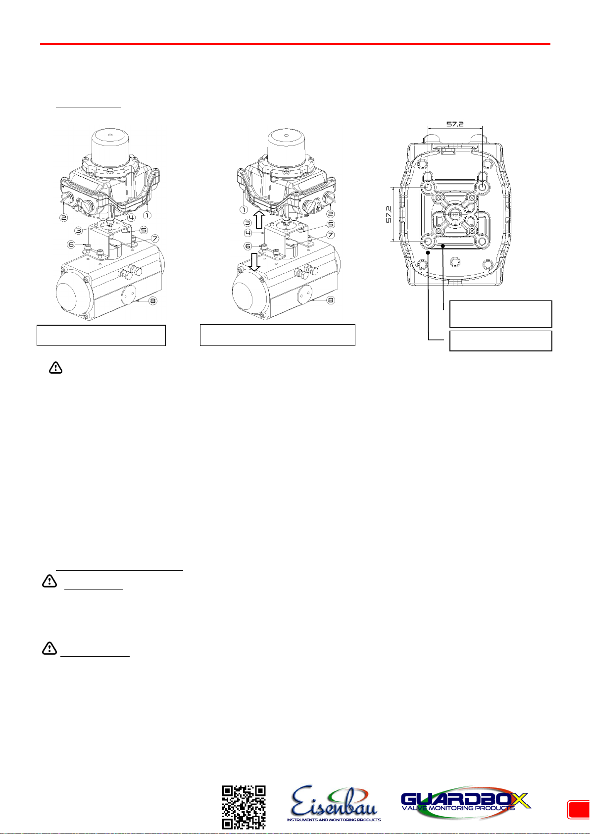
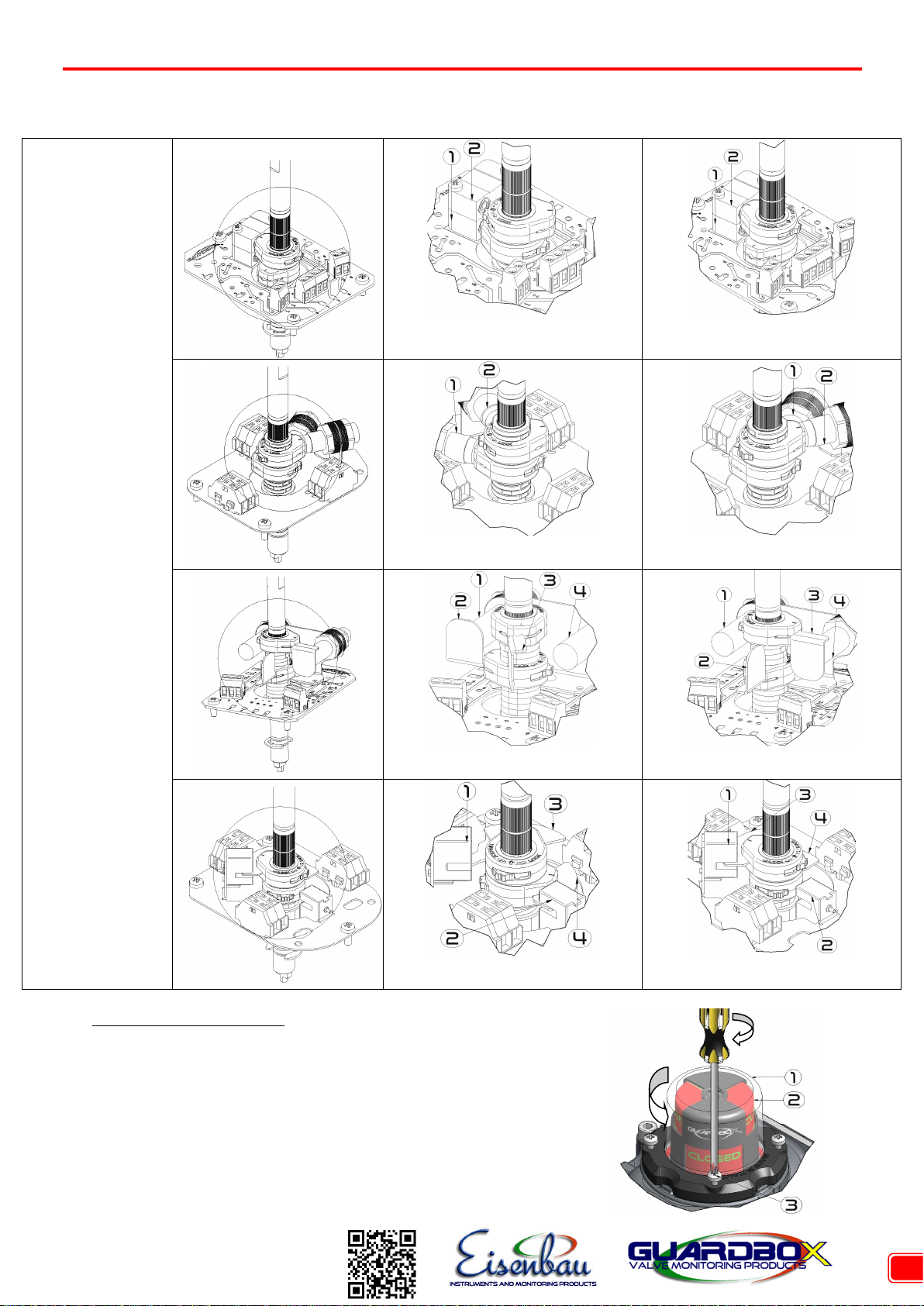
5. Installation
QR code or data matrix to
directly download drawings,
wiring diagrams and manuals
directly on field