EK-Quantum Reflection 2 PC-O11D EVO XL D5 PWM D-RGB User manual
USER GUIDE
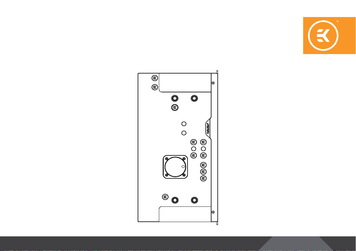
DISTRIBUTION PLATE
EKQuantum
Reflection2PC-O11D EVO XL D5 PWM D-RGB

Please note the installation of the product is intended to be
undertaken by an adequately trained and experienced person.
You are installing the product at your own risk. If you are not
properly trained or experienced or feel unsure about the
installation procedure, please refrain from installing the product
yourself and contact our tech support for assistance. We disclaim
our liability for any damages to the product as well as incidental,
consequential, or indirect damages incurred due to improper or
inappropriate installation.
Before you start using this product please follow these basic guidelines:
Please carefully read the manual before beginning with the
installation process!
The EK Fittings require only a small amount of force to screw
them firmly in place since the liquid seal is ensured by the
rubber O-ring gaskets.
The use of corrosion-inhibiting coolants is always recommended
for any liquid cooling system. EKWB recommends any of the
EKCryofuel for worry-free usage.

- 3 -
TABLE OF CONTENT
BOX CONTENTS 4
DISTRIBUTION PLATE DIMENSIONS 5
TECHNICAL SPECIFICATIONS AND PRODUCT PARTS 6
PREPARING THE 011D EVO XL CHASSIS 7
INSTALLING THE DISTRIBUTION PLATE 8
RECOMMENDED DISTRIBUTION PLATE CONFIGURATIONS 10
ATTACHING THE PUSH-IN ADAPTERS (OPTIONAL) 12
FLOW DIAGRAM 13
CONNECTING THE D-RGB LED STRIP 14
CONNECTING THE PUMP 14
TESTING THE LOOP 15
SUPPORT AND SERVICE 16
SOCIAL MEDIA 16
- 4 -
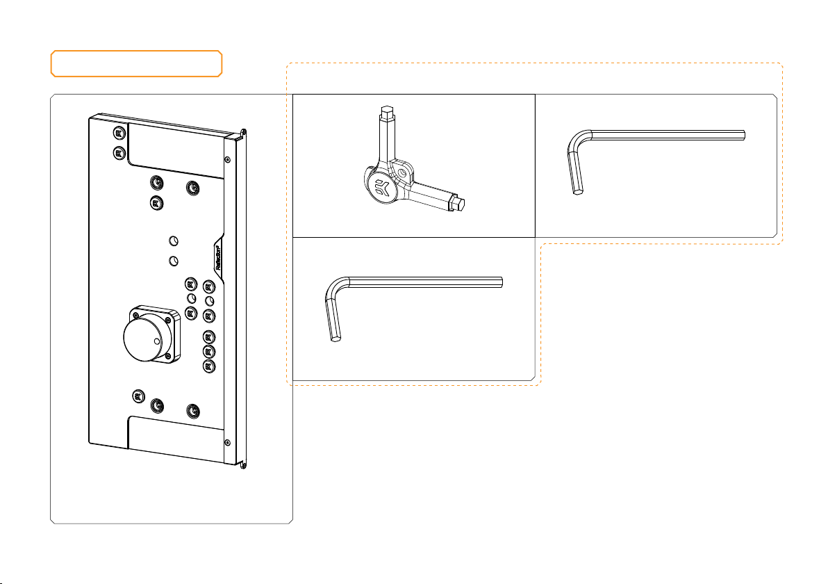
BOX CONTENTS
EK-Quantum Reflection2PC-O11D
EVO XL D5 PWM D-RGB
Allen Key 2.5 mm (1 pc)
Allen Key 2 mm (1 pc)
EK-Loop Multi Allen Key (1 pc)
Mounting Mechanism EAN: 107076
- 5 -
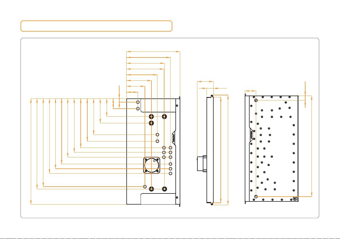
DISTRIBUTION PLATE DIMENSIONS
230 mm
49 mm
79 mm
107 mm
132.6 mm
163 mm
160.6 mm
188.6 mm
454.5 mm
15 mm
43 mm
77 mm
105 mm
154.7 mm
182.7 mm
210.7 mm
231 mm
251.4 mm
280.7 mm
301 mm
321.4 mm
378 mm
388 mm
29 mm
69.8 mm
472.3 mm
454.5 mm
47.5 mm
20 mm
433.5 mm

- 6 -
TECHNICAL SPECIFICATIONS AND PRODUCT PARTS
16
4
20
10
15
21
9
Technical Specification:
-
Dimensions with the attached pump (W x D x H): 230 x 75 x 472mm
- D-RGB LED count: 21
- D-RGB cable length: 500 mm
- D-RGB connector standard 3-pin (+5V, Data, Blocked, Ground)
Position EAN Description Quantity
1106947 Top plate (Plexi) 1
23831109837597 EK-D5 Pump 1
35154 OR 52 x 3 mm 1
4105913 Pump holder 1
5104599 Mylar sticker 2
6100663 EK - Badge 1
7106950 Led Cover (Black e.) 1
8100815
LED D-RGB strip
1
9102639
EK Plug G1/4
13
10 107067 OR - Reflection2EVO XL 1-6 1
11 107068 OR - Reflection2EVO XL 2-5 1
12 107069 OR - Reflection2EVO XL 3-5 1
13 107070 OR - Reflection2EVO XL 4-5 1
14 107071 OR - Reflection2EVO XL 5-6 1
15 107072 OR - Reflection2EVO XL 6-6 1
16 8311 Screw M4 x 20 DIN7984 4
17 9039 Screw M4 x 18 DIN7991 61
18 9044 Screw M4 x 8 DIN7991 2
19 106946 Bottom plate (Plexi) 1
20 3831109895313 EK-Quantum Torque Push-In
Adapter 5
21 3831109834282
Plug Cover
13
2
3
19
1
14
13
8
12
18
11
6
17
5
7

- 7 -
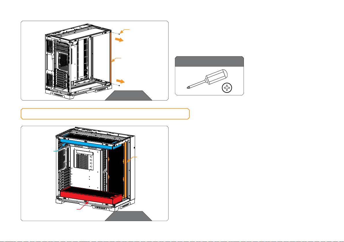
PREPARING THE 011D EVO XL CHASSIS
STEP 1
Unscrew the factory-provided screws and remove the top panel
from the case.
STEP 2
STEP 2
Remove both side panels and the front panel from the case.
STEP 1
- 8 -
STEP 3
STEP 3
Using the Philips Head Screwdriver, unscrew the factory-provided
side panel screws and remove the side panel. Save the screws for
later steps!
For this step you will need:
Phillips-head screwdriver
SIDE PANEL
SCREW
SIDE PANEL
SIDE
RADIATOR
(MAX P420M)
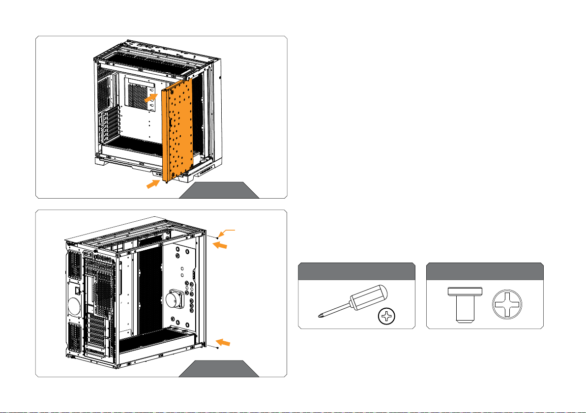
INSTALLING THE DISTRIBUTION PLATE
STEP 1
Important! Before placing the distribution plate, you must install
the radiators in the following order:
First: Side radiator
Second: Bottom radiator
Third: Top radiator
STEP 1
BOTTOM RADIATOR
(MAX X420M)
TOP RADIATOR
(P420M);
(X420M in
motherboard
top tray
configuration)
- 9 -
STEP 3
STEP 3
Secure the distribution plate using the saved Side panel screws. The
screws shouldn’t be over-tightened to avoid cracking the acrylic.
STEP 2
STEP 2
Position the distribution plate into the PC Case. Make sure to align
the mounting holes. Be careful not to scratch the acrylic parts!
For this step you will need:
Phillips-head screwdriver Side panel screw (2 pcs)
SIDE PANEL
SCREW
- 10 -
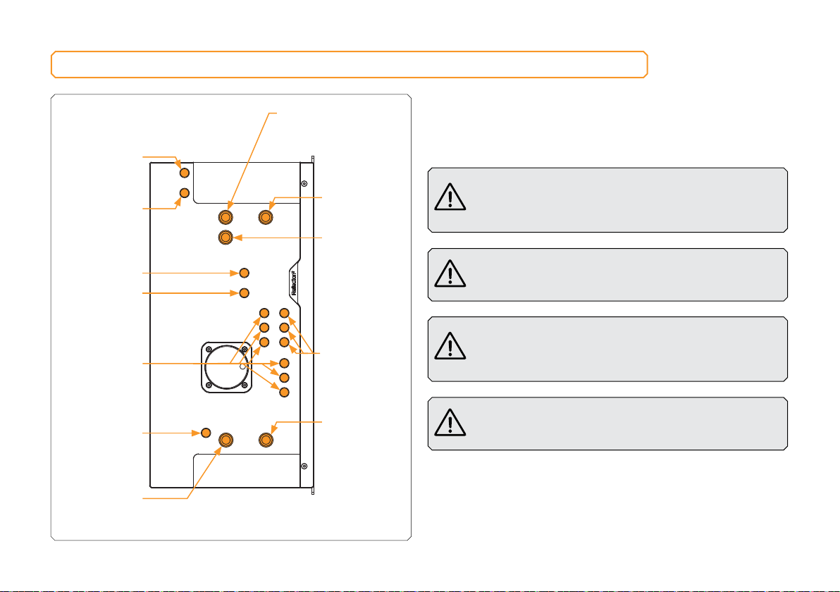
RECOMMENDED DISTRIBUTION PLATE CONFIGURATIONS
SIDE RADIATOR
OUTLET
TOP RADIATOR
INLET
BOTTOM
RADIATOR
OUTLET
SIDE RADIATOR
INLET
CPU OUTLET
CPU INLET
TOP RADIATOR
OUTLET
(DUAL
RADIATOR
CONFIGURATION)
TOP RADIATOR OUTLET
(TRIPLE RADIATOR
CONFIGURATION)
GPU INLET
(OPTIONAL)
GPU OUTLET
(OPTIONAL)
DRAIN PORT (FILL
PORT IN FLIPPED
CONFIGURATION)
BOTTOM
RADIATOR
INLET
To complete your loop, all ports must be used as marked in the
image.
All remaining unused ports must be closed with supplied plugs,
using the EK-Loop Multi Allen Key.
If one of the prescribed components will not be installed
(ie. bottom radiator or GPU block) then one INLET and
one OUTLET port must still be joined together in order
for this distribution plate to function!
Note that the side radiator is completely optional and a
loop without the side radiator can be completed without
joining the two side radiator ports.
Only one INLET and one OUTLET port for the GPU
connection can be used, while all other INLET and
OUTLET GPU ports must be closed with G1/4 plugs
(enclosed in the package).
The distribution plate is designed to function in both
regular and inverted case configurations. Inverting the
case does not change the port configuration.
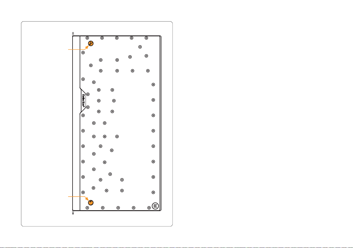
- 11 -
FILL PORT (DRAIN
PORT IN FLIPPED
CONFIGURATION)
DRAIN PORT (FILL
PORT IN FLIPPED
CONFIGURATION)
- 12 -
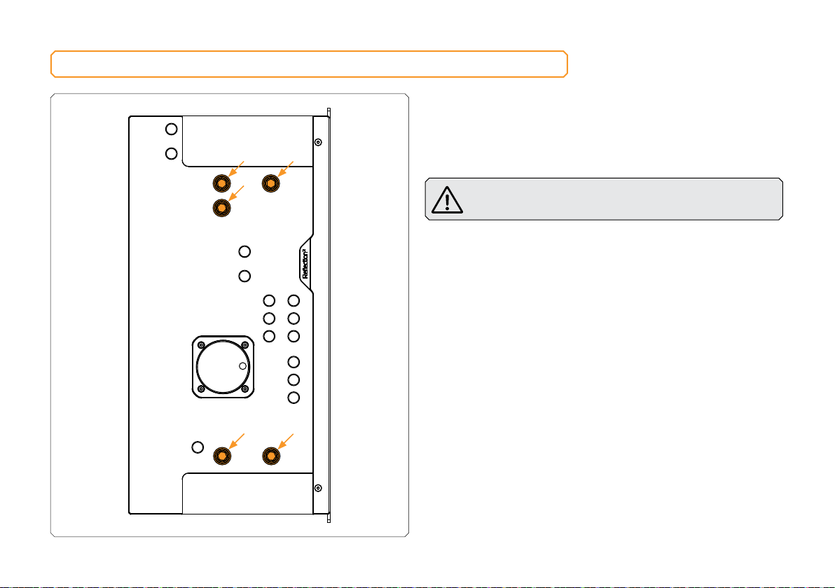
ATTACHING THE PUSH-IN ADAPTERS (OPTIONAL)
The push-in adapters can be attached to the marked places in the
diagram.
For easier push-in adapters’ installation, EK recommends lubricating
the O-rings with a few drops of coolant or water.
Important! Only the M7 Push-in Adapters are compatible
with this distribution plate!
- 13 -
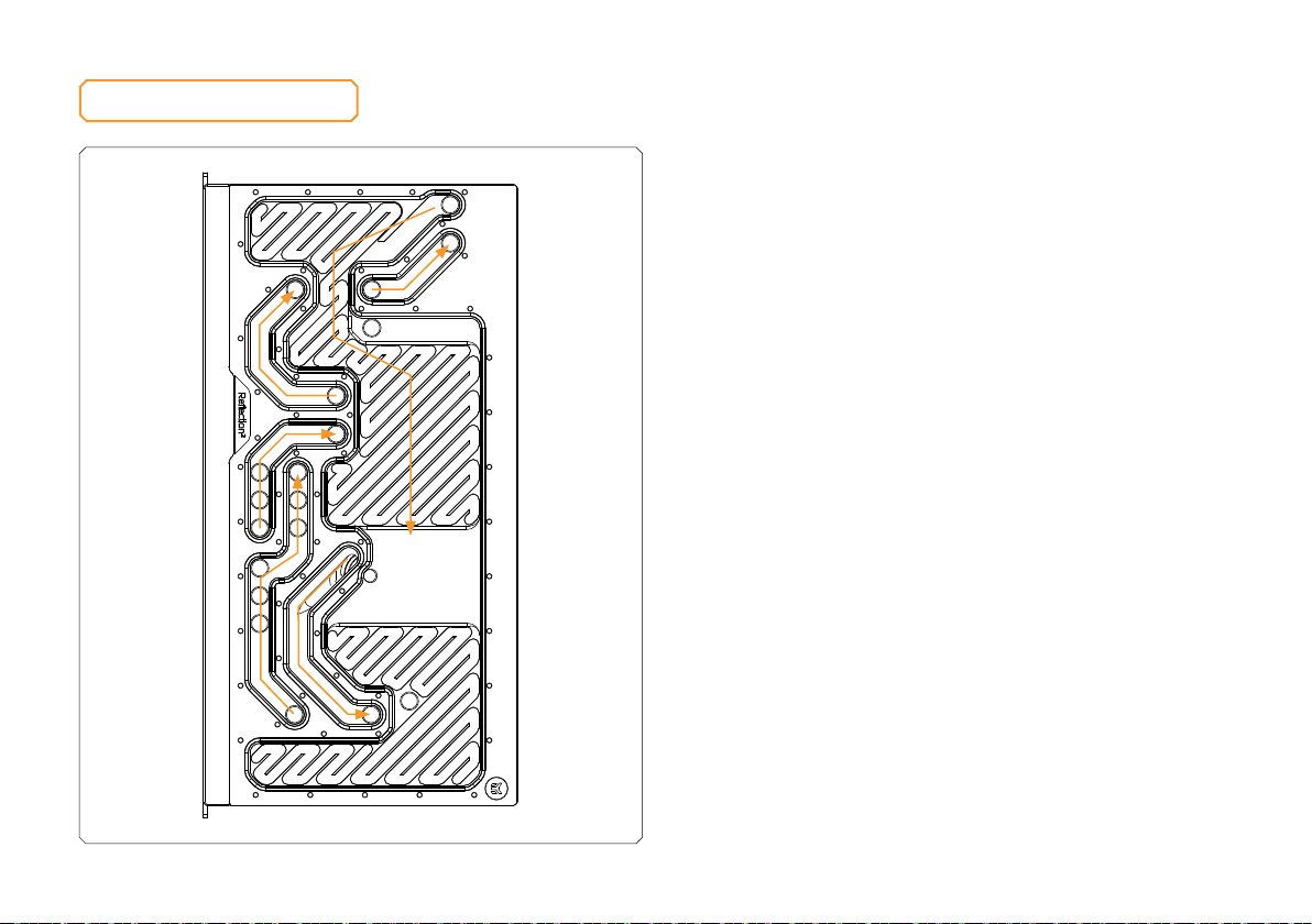
FLOW DIAGRAM
- 14 -
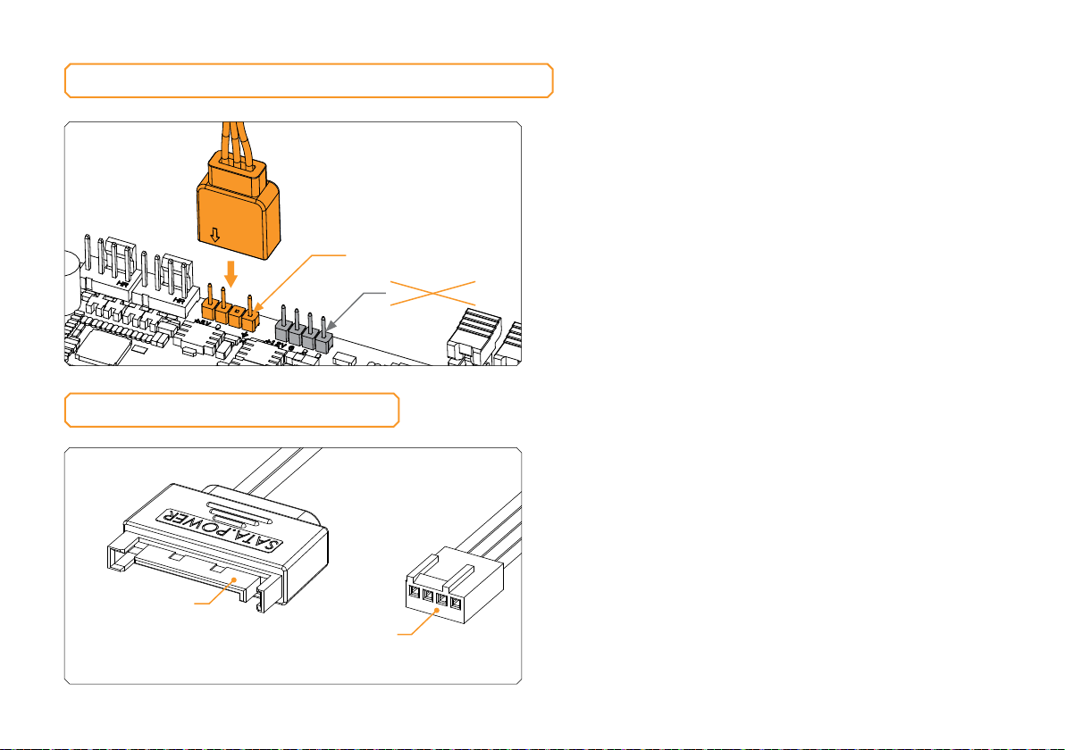
CONNECTING THE D-RGB LED STRIP
Plug the 3-pin connector of the distribution plate D-RGB LED light
to the D-RGB HEADER on the motherboard. The LED will work if the
pin layout on the header is as follows: +5V, Digital, Empty, Ground.
D-RGB Header
RGB Header
CONNECTING THE PUMP
The EK-D5 PWM pump has two connectors.
1. SATA Connector: It must be connected directly to your PSU at all
times as it is used to power the pump.
2. 4-pin PWM fan: It can be connected to your motherboard’s
CPU_ Fan or designated water pump header. It can also be
connected to a controller. This cable is used to control and report
the rotational speed of the pump. If it’s not connected, the pump
will run at maximum speed (100% PWM).
SATA
CONNECTOR 4-PIN PWM FAN
CONNECTOR

- 15 -
To make sure the installation of EK components was successful, we
recommend you perform a leak test for 24 hours.
When your loop is complete and filled with coolant, connect the
pump to a PSU outside of your system. Do not connect power to
any of the other components. Turn on the PSU and let the pump
run continuously. It is normal for the coolant level to drop during this
process as air collects in the distribution plate.
Inspect all parts of the loop, and in the eventuality that coolant leaks,
fix the issue and repeat the testing process. Ensure that all hardware is
dry before the system is powered on in order to prevent any damage.
TESTING THE LOOP
In case you need assistance or wish to order spare parts or a new
mounting mechanism, please contact:
https://www.ekwb.com/customer-support/
For spare parts orders, refer to the page with “TECHNICAL
SPECIFICATIONS AND PRODUCT PARTS” where you can find the
EAN number of each part you might need.
Include the EAN number with quantity in your request. Mounting
Mechanism EAN can be found under “BOX CONTENTS”
Thermal pads are readily available in the EK shop
EKWaterBlocks
@EKWaterBlocks
ekwaterblocks
ekwaterblocks
EKWBofficial
SUPPORT AND SERVICE
SOCIAL MEDIA
Table of contents


