Ekars ETR-2112 User manual
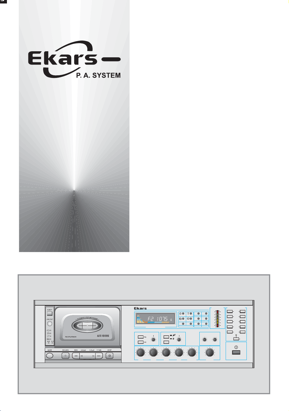
ETR-2112
Cassette Deck
Tuner Amplifier
OPERATING MANUAL
TUNER/CD MASTER
Min Max
AUX
MIC-3MIC-2MIC-1
Min Max
Min Max
Min Max
Min Max
Min Max
Min Max Min Max
SIREN CHIME
TUNE / TRACK
CHIME
FM / AM DIGITAL TUNER
LEVEL METER
Bass Treble
-12dB +12dB -12dB +12dB
SPEAKER SELECTOR
CASSETTE DECK TUNER AMPLIFIER ETR-2112
1
3
5
7
9
2
4
6
8
10
ALL
POWER
100
80
60
40
20
10
+3
0
3
6
12
16
18
24
dB
- dB% Pow
M2
M4
M6M5
M3
M1
MODE BAND
POWER SCAN SCAN
SHUF
DISC UP
PAU SE
REPEAT
DISC DN
00
UP
DN

Contents
1.Unpacking And Installation -------------------------------------------------------- 2
2.Features --------------------------------------------------------------------------------- 3
3.Front Panel Controls ---------------------------------------------------------------- 4
4.Cassette Deck ----------------------------------------------------------------------- 5
5.Tuner Section ------------------------------------------------------------------------ 6
6.Rear Panel Controls --------------------------------------------------------------- 7.8
7.Application Of The Antenna ---------------------------------------------------- 9
8.Installation Of The Speaker ----------------------------------------------------- 10
9.Specifications ---------------------------------------------------------------------------- 11
1
SamHyoung Electronics Co., Ltd.
3Ra-618, Shihwa Industrial Complex, #1378, Jungwang-Dong,
Shiheung-City, Kyonggi-Do, Korea (429-450)
Tel : 82)31+432+5112 / 82)31+432+4422
Fax: 82)31+432+5450 / 82)31+431+1690
Home Page : http://www.ekars.co.kr
http://www.samhyoung.co.kr

Unpacking And Installation
2
CAUTION
CAUTION
RISK OF ELECTRIC SHOCK
DO NOT OPEN
RISK OF ELECTRIC SHOCK
DO NOT OPEN
CAUTION
:
TO REDUCE THE RISK OF ELECTRIC SHOCK.
DO NOT REMOVE COVER (OR BACK).
NO USER-SERVICEABLE PARTS INSIDE.
REFER SERVICING TO QUALIFIED
SERVICICE PERSONNEL.
TO PREVENT FIRE OR SHOCK HAZARD,
WARNING
:
DO NOT EXPOSE THE UNIT TO RAIN OR
MOISTURE.
This symbol is intended to alert the user to the
presence of important operation and maintenance
(servicing) instructions in the literature
accompanying the appliance.
This symbol is intended to alert the user to the
presence of uninsulted "dangerous voltage"
with in the product's enclosure that may be of
sufficient magnitude to constitute a risk of
electric shock to persons.
To prevent electric shock do not use this
(polarized) plug with an extension cord,
receptacle or other outlet unless the blades can
be fully inserted to prevent blade exposure.
:
CAUTION
Although it is neither complicated to install nor difficult to operate your Cassette Deck-
Tuner Amplifier, a few minutes of your time is required to read manual for a properly
wired installation and becoming familiar with its many features and how to use them.
Please take a great care in unpacking your Cassette Deck-Tuner Amplifier and do not
discard the carton and other packing materials.
They may be needed with when moving your set and are required if it ever becomes
necessary to return your set for service.
Never place the unit radiators, in front of heating vents, in excessively humid or dusty
location to avoid early damage and for your years of quality use.
Connect your complementary components as illustrated in the following page.
The instruction for use shall state that the apparatus shall not be exposed to dripping or
splashing and that no objects filled with liquids, such as vases, shall be placed on the
apparatus.

Features
120W OUTPUT POWER
This model can deliver very high output power at less than 1% THD.
VERSATILE AND EASY TO USE
Incorporating all the necessary system components to provide versatility in an easy
to use form : five channels of input signals. (MIC/LINE 1~3, AUX and CD/Tuner).
PRIORITY AND MUTING
Input to Mic 1 will activate the priority circuit which temporarily mutes signals
from other inputs, tuner or tape. Input also activates muting.
TONE CONTROL
MASTER : The two band tone control provides ±12dB of control over
the TREBLE and BASS range.
SIREN WITH TWO TONES
Penetrating warning sound for emergency use operated by front panel buttons
with two tone ways and level volume control.
CHIME
Melodious chime for pre-announcements finishing operated by front panel button
with two tone ways and level volume control.
DIGITAL TUNER
Ability to store up to thirty broadcasting frequencies in the system's memory,
in a simple and easy to use manner.
CASSETTE DECK
Autorever CASSETTE DECK-MECHANISM can be made play back rewrding
of magnetic tape by function button.
TELEPHONE IN TERMINAL
These terminals are to be connected to telephone exchange system for paging.
10 ZONE SELECTOR
10 SP channel selector switches are provided to enable you to select 10 zone
speakers individually.
ALL SELECTION
By using ALL, you can drive the speakers of all zones.
3

Front Panel Controls
4
1. POWER SWITCH
Pressing this switch to ON will make the power indicating LED ON and supply
the power to this unit.
2. LEVEL METER INDICATOR
These LEDs indicate the output level.
3. ALL SELECTION
By using ALL, you can drive the speakers of all zones.
4. 10 ZONE SELECTOR
10 SP channel selector switches are provided to enable you to select 10 zone speakers
individually.
5. SIREN
Pressing this button selectively will activate your wanted tone siren circuitry with
volume level control.
6. CHIME
Pressing this button will activate chime circuitry with volume level control.
7. MASTER VOLUME
This control is used for adjusting the volume of finally mixed sound.
8. TONE CONTROL
The tone control section of master volume provides +/-12dB of control over the
TREBLE and BASS range. These frequency ranges are
TREBLE : 10KHz , BASS : 100Hz
9. INPUT CH1~CH5 VOLUME
These volume controls adjust the level of MIC1~3, AUX, Tuner/CD.
TUNER/CD MASTER
Min Max
AUXMIC-3MIC-2MIC-1
Min Max
Min Max
Min Max
Min Max
Min Max
Min Max Min Max
SIREN CHIME
TUNE / TRACK
CHIME
FM / AM DIGITAL TUNER
LEVEL METER
Bass Treble
-12dB +12dB -12dB +12dB
SPEAKER SELECTOR
CASSETTE DECK TUNER AMPLIFIER ETR-2112
1
3
5
7
9
2
4
6
8
10
ALL
POWER
100
80
60
40
20
10
+3
0
3
6
12
16
18
24
dB
- dB% Pow
M2
M4
M6
M5
M3
M1
MODE BAND
POWER SCAN SCAN
SHUF
DISC UP
PAU SE
REPEAT
DISC DN
00
UP
DN
1
23
4
56789
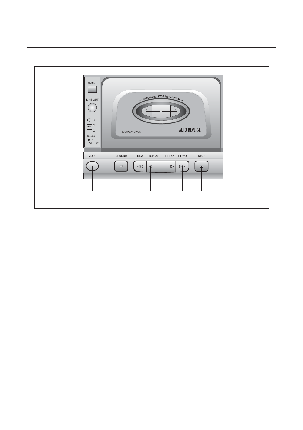
1. Cassette Deck Section
5
1. EJECT BUTTON
Door to open for remving and inserting the MAGNECTIC TAPE
2. LINE OUT VOLUMNE
This control is used for adjusting the volume of CASSETTE DECK
3. MODE BUTTON
This button is used for selecting the PLAYBACK mode.
4. RECORD BUTTON
This button is used for recording
5. REW BUTTON
This button is used for rewinding
6. R-PLAY BUTTON
This button is used for reverse play back.
7. F-PLAY BUTTON
This button is used for forward play back
8. FFWD
9. STOP BUTTON
1
23 4
5678 9
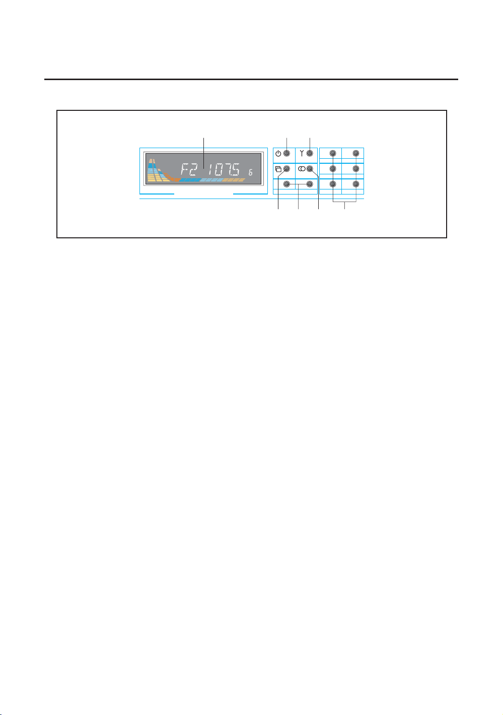
2. Tuner Section
6
1. TUNING FREQUENCY DISPLAY
You can confirm the frequency of tuner through this display.
2. POWER ON/OFF
This button is used for tuner power On/Off.
3. MODE BUTTON
This button is used for selecting the Tuner mode.
4. BAND SELECT BUTTON
This button is used for selection MW(=AM) or FM 1,2, or 3,
when using the tuner. (4 band 24 memory)
5. TUNE SCAN BUTTON
When this button pressing, the radio searches for each preset stations.
When the field strengh level is more than the threshold level of stop level,
the radio is holding at that preset number for 5 sec with releasing mute,
and than searches again.
When shorting pressing, the radio select a preset station directly.
6. UP/DOWN BUTTON
When the button is momentarily pressed once, the MW(=AM)/FM frequency will
adjust with a single UP/DOWN count.
When the button is pressed continuously, the frequency is continuously
fast UP/DOWN counted.
7. MEMORY BUTTON
This is for memorizing the broadcasting frequency.
1. Select the memory area MW(=AM) or FM with the BAND switch (4).
2. Select the frequency that you want to memorize with the UP/DOWN switch (6).
3. Select the desired address with ADDRESS switch (7), then press more than 1 sec.
4. The present status of the tuner will be memorized in the selected address.
TUNE / TRACK
FM / AM DIGITAL TUNER
M2
M4
M6M5
M3
M1
MODE BAND
POWER SCAN SCAN
SHUF
DISC UP
PAUS E
REPEAT
DISC DN
UP
DN
12
3 4
5
67
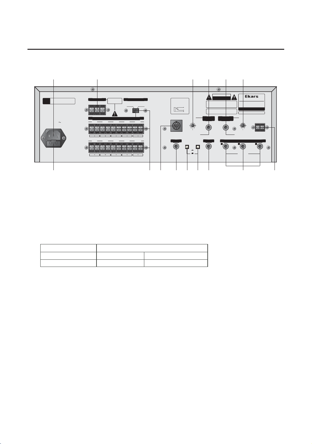
Rear Panel Controls
7
1. FUSE HOLDER
This fuse holder contains the AC fuse. If blown, replace it with same
type fuse as specified below. If the fuse continuously blows, refer
servicing to qualified personnel.
MODEL ETR-2112
VOLTAGE AC 115V AC 220V ~ 240V
FUSE RATING T3A / 250V T 2A / 250V
2. AC INLET
This is the AC INPUT for the AC INPUT CORD.
3. ANTENNA TERMINAL
This terminals for connecting the antenna terminal, when you can use
the tuner.
4.5. TELEPHONE IN CONNECTOR WITH INPUT LEVEL
These terminals are to be connected to telephone exchange system
for paging.
NOTE: When there are paging signal through this terminal, all other
input signals except AMP IN are muted. Also, you can adjust
to input level controls by the volume of internal unit.
And MIC1 signal is similar priority function with telephon audio
signal. However, MIC1 and telephone audio signal priority function
can be defeated by the priority switch.
COM
SP-1 SP-2 SP-3 SP-4 SP-5
COM HOT COM HOT COM HOT COM HOT COM HOT
COM HOTCOM HOT
COM HOTCOM HOTCOM HOT
SP-6 SP-7 SP-8 SP-9 SP-10
6CDC LINK ANTENNA
GND
AM/FM
TUNER
BACKUP
TUNER
BACKUP
INPUT
LEVEL
INPUT
LEVEL
LOW IM PE DA NCE
OPTION
<ECC-2612>
OPTION
<ECC-2612>
32 1
PRE OUT MIC INPUT
AUX INPUT
TELEPHONE
IN
TELEPHONE
IN
OUTPUT
LEVEL
OUTPUT
LEVEL
MUSIC ON HOLD
TUNER/CD
MUSIC ON HOLD
TUNER/CD
BALANCED
: -54dB(2mV)
BALANCED
: -54dB(2mV)
BALANCED
: -10dB(300mV)
BALANCED
: -10dB(300mV)
BALANCED
: +2dB( 1. 25V )
BALANCED
: +2dB( 1. 25V )
75Ω
75Ω
4Ω
4Ω
8Ω
8Ω
INPUT
TELEPHONE PAGING
-20dB(100mV) BAL
INPUT
TELEPHONE PAGING
-20dB(100mV) BAL
OUTPUT
MUSIC ON HOLD
0dB(1000mV) UNBAL
OUTPUT
MUSIC ON HOLD
0dB(1000mV) UNBAL
IMPEDANCE SELECTOR
70.7V
(40.8Ω)
70.7V
(40.8Ω)
100V
(83.3 )Ω
100V
(83.3 )Ω
S
T
R
-TIP(+) : HOT
T
R - RIN G(- ) : COL D
S - SLEEVE(G) : GND
SPEAKER SELECTOR OUTPUT
OFF
ON
PLEASE
DO NOT USE
SIMULTANEOUSLY
PLEASE
DO NOT USE
SIMULTANEOUSLY
MIC1, TEL
INPUT
PRIORITY
MIC1, TEL
INPUT
PRIORITY
SN
MaxMin MaxMin
50/60Hz. 230W
AC INPUT
220V 240V
-
AC FUSE
T2AL 250V
AC FUSE
T2AL 250V
TO REDUCE THE RISK OF FIRE
OR ELECTRIC SHOCK DON'T EXPOSE THIS
EQUIPMENT TO RAIN OR MOISTURE.
WARN ING
:
TO REDUCE THE RISK OF FIRE
TO REDUCE THE RISK OF FIRE
REPLACE ONLY WITH SAME TYPE FUSE.
CAUTION
:
CAUTION
CAUTION
RISK OF ELECTRIC SHOCK
DO NOT OPEN
RISK OF ELECTRIC SHOCK
DO NOT OPEN
MADE IN KOREA
MADE IN KOREA
www.ekars.co.kr
CASSETTE DECK AND
CASSETTE DECK AND
DIGITAL TUNER AMPLIFIER
DIGITAL TUNER AMPLIFIER
OUTPUT POWER 120W RMS
OUTPUT POWER 120W RMS
MODEL NO : ETR-2112
MODEL NO : ETR-2112
1
2
3
4
567
89 12
12
10
10
11
11
13
13
15
15
14
14

Rear Panel Controls
8
6.7. MUSIC-ON HOLD (CD AND TUNER ONLY WITH OUTPUT LEVEL)
These terminals are for connecting to the telephone system.
NOTE: When the tuner or CD is turned on, its output signal is always
supplied to these terminals and is not concerned with master
volume. Also, you can adjust to output
level by the volume of internal unit.
8. AUX INPUT CONNECTOR
The sound source (from CD palyer etc.)is connected to this input.
9. PRE OUTPUT CONNECTOR
The pre out signal of this unit can be used for connecting to another
amplifier, e.g. Recorder or signal processor etc.
10. CH1~CH3 MIC INPUT XLR JACK
These are MIC input connectors which are designed electrical
balanced circuitry.
11. TUNER BACKUP SWITCH
Be sure to press this switch before installation.
This is for memory backup of the broadcasting frequency.
12. MIC1, TEL INPUT PRIORITY SWITCH
MIC1 signal is similar priority function with telephone audio signal.
13. 6CDC LINK CONNECTOR
This connector for connecting the optionable external 6CD changer
(ECC-2612) when you purchase seperately.
14. LOW INPEDANCE
These terminals are for connection to low impedance (4Ω, 8 Ω) speakers.
15. HIGH INPEDANCE (SPEAKER SELECTOR OUTPUT TERMINALS)
These terminals are for connection of speaker lines to deliver power
output to speaker. Impedance (voltages) of 70V and 100V are
provided for convenience. In any case, use the speakers whose
combined is equal to or higher than the rated output impedance
of amplifier.
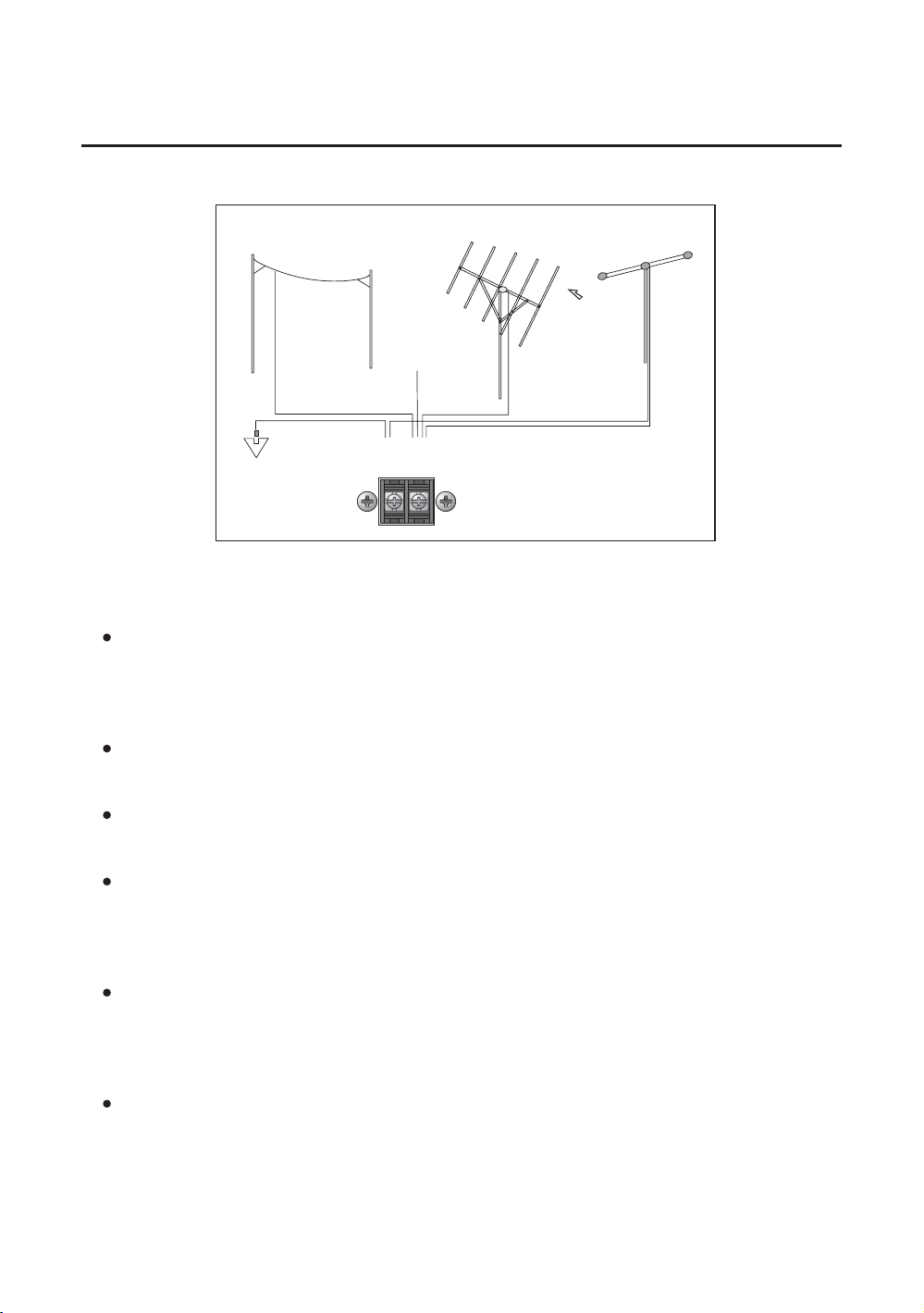
Application Of The Antenna
9
SINGLE CONDUCTOR LEAD WIRE ANTENNA
Connecting the single conductor lead wire antenna of the terminal
of 75 ohms(Picture).
Listening to the broadcasting, fix it after desiding the location and
the direction so that the receipt condition may be optimum.
FM RECEIVING ANTENNA
The electric wave of FM broadcasting is weakening in hills and valleys,
around buildings and in iron-reinforced buildings.
INSTALLATION OF ANTENNA EXCLUSIVELY FOR FM
Listening to the broadcasting, fix the antenna after deciding the location
and the direction so that the reception may be optimized.
INSTALLATION OF ANTENNA USING THE COAXIAL CABLE
Noisy reception may occur in built-up areas and factory sites as around
power cables. This may be the case even when an antenna is used
exclusively for FM. In these regions, install the antenna using 75 ohm
coaxial cable.
INDOOR ANTENNA
In the regions where FM broadcasting is heard comparatively well due
to the near distance to the station or wooden structure, you can receive
broadcasting of good quality by using T-type antenna. (Using matching
trans:300/75 ohms)
AM OUTDOOR ANTENNA
Install the vinyl-coated cable to an outdoor place if the AM reception is
not good enough.
ANTENNA
GND
AM/FM
75Ω
75Ω
FM DIPOLE ANTENNA
SINGLE CONDUCTOR
LEAD WIRE
DIRECTION OF
BROADCASTING
STATION
OUTDOOR FM ANTENNAAM OUTDOOR ANTENNA

Installation of The Speaker
10
Before you connect the speaker, remove the power cord from the power
outlet and switch the ETR-2112 power switch off. When connecting the
speaker wires to the SPEAKER OUTPUT terminals, use the output
terminals that are suitable for the speaker (see above figure 1-4).
Extreme care must be exercised when connecting to these terminals as
potentially hazardous voltages may be present.
NOTE : Do not exceed the power rating of the amplifier by connecting
more speakers than the unit is rated for. If you are in doubt,
please consult a professional installer.
(Figure 1)
FOR 4 LINEΩ
COM
SP-1 SP-2 SP-3 SP-4 SP-5
COM HOT COM HOT COM HOT COM HOT COM HOT
COM HOTCOM HOT
COM HOTCOM HOTCOM HOT
SP-6 SP-7 SP-8 SP-9 SP-10
LOW IMPEDANCE
4Ω
4Ω
8Ω
8Ω
IMPEDANCE SELECTOR
70.7V
(40.8Ω)
70.7V
(40.8Ω)
100V
(83.3 )Ω
100V
(83.3 )Ω
SPEAKER SELECTOR OUTPUT
PLEASE
DO NOT USE
SIMULTANEOUSLY
PLEASE
DO NOT USE
SIMULTANEOUSLY
SPEAKER
OUTPUT
4Ω8Ω8Ω
OR
(Figure 2)
FOR 8 LINEΩ
COM
SP-1 SP-2 SP-3 SP-4 SP-5
COM HOT COM HOT COM HOT COM HOT COM HOT
COM HOTCOM HOT
COM HOTCOM HOTCOM HOT
SP-6 SP-7 SP-8 SP-9 SP-10
LOW IMPEDANCE
4Ω
4Ω
8Ω
8Ω
IMPEDANCE SELECTOR
70.7V
(40.8Ω)
70.7V
(40.8Ω)
100V
(83.3 )Ω
100V
(83.3 )Ω
SPEAKER SELECTOR OUTPUT
PLEASE
DO NOT USE
SIMULTANEOUSLY
PLEASE
DO NOT USE
SIMULTANEOUSLY
4Ω
4Ω
OR
16Ω16Ω8Ω
SPEAKER
OUTPUT OR
COM
SP-1 SP-2 SP-3 SP-4 SP-5
COM HOT COM HOT COM HOT COM HOT COM HOT
COM HOTCOM HOT
COM HOTCOM HOTCOM HOT
SP-6 SP-7 SP-8 SP-9 SP-10
LOW IMPEDANCE
4Ω
4Ω
8Ω
8Ω
IMPEDANCE SELECTOR
70.7V
(40.8Ω)
70.7V
(40.8Ω)
100V
(83.3 )Ω
100V
(83.3 )Ω
SPEAKER SELECTOR OUTPUT
PLEASE
DO NOT USE
SIMULTANEOUSLY
PLEASE
DO NOT USE
SIMULTANEOUSLY
SP-1 SP-10
With
Matching
Trans
SPEAKER
OUTPUT
(Figure 3)
FOR 70V LINE
70V
COM
SP-1 SP-2 SP-3 SP-4 SP-5
COM HOT COM HOT COM HOT COM HOT COM HOT
COM HOTCOM HOT
COM HOTCOM HOTCOM HOT
SP-6 SP-7 SP-8 SP-9 SP-10
LOW IMPEDANCE
4Ω
4Ω
8Ω
8Ω
IMPEDANCE SELECTOR
70.7V
(40.8Ω)
70.7V
(40.8Ω)
100V
(83.3 )Ω
100V
(83.3 )Ω
SPEAKER SELECTOR OUTPUT
PLEASE
DO NOT USE
SIMULTANEOUSLY
PLEASE
DO NOT USE
SIMULTANEOUSLY
SP-1 SP-10
With
Matching
Trans
SPEAKER
OUTPUT
(Figure 4)
FOR 100V LINE
100V

Specifications
11
AMPLIFIER SECTION
Rated Output -------------------------------------------------- 120Watts(RMS)
Frequency Response ----------------------------- 60Hz ~ 18KHz (+/-3dB)
S/N Ratio
Mic 1-3 ------------------------------------------------------- more than 60dB
Aux ----------------------------------------------------------- more than 65dB
THD ---------------------------------------------------- less than 1%(@ 1KHz)
Tone Controls
Master volume ------------------------------------ Bass +/-12dB at 100Hz
Treble +/-12dB at 10KHz
Input Sensitivity/Impedance
Mic 1-3 ----------------------------------------- 2mV/600 ohms (Balanced)
Line Input 1-5 ----------------------------- 250mV/10K ohms (Balanced)
Aux ---------------------------------------------------------- 250mV/10Kohms
Telephone ------------------------------------------------- 100mV/600 ohms
REC/Line output --------------------------------------- 1000mV/10K ohms
Speaker Output/Impedance -------------------- 22V/4ohms, 31V/8ohms
70V/41ohms, 100V/83ohms
DECK SECTION
TYPE ------------------------------------ 2 Track Mono PlayBack Recoding
Wow Flutter ---------------------------------------------------- Less then 0.3%
Tape Speed -------------------------------------------------------- 4.76Cm/Sec
CD SECTION
Type ------------------------------------------- 6CD changer Magazine Type
T.H.D ---------------------------------------------- Less than 0.3%( @ 1KHz)
Frequency Response ----------------------------- 30Hz ~ 20KHz (+/-3dB)
SPEAKER SELECTOR SECTION
Speaker selector ------------------------------------------ 10 Channels, ALL
General
Power Requirements --------------------------- AC 220V~240V, 50/60Hz
Power Consumption ------------------------------------------------------ 230W
Net Weight(kg/Ib)-------------------------------------------------------- 12.5/ 28
Dimensions ---------------------------------- 430(W) x 132(H) x 310(D)mm
16.9(W) x 5.19(H) x 12.2(D)inch
Specifications and design are subjected to change without notice
for improvements.

Memo
12

Memo
13

Memo
14

3rd floor, 271-183, Kochk-2Dong,
Guro-Gu, Seoul, Korea (152-082)
Tel : 82)2+2612+4422
Fax : 82)2+2612+7676
Seoul office.
936-4, Kumuncheoun-Ri, Hyangnam-Myun,
Hwaseong-City, Kyunggi-Do, Korea (445-922)
Tel : 82)31+432+5112 / 82)31+432+4422
Fax : 82)31+352+7637 / 82)31+352+7649
Home Page : http://www.ekars.co.kr / http://www.samhyoung.co.kr
Headquarter & Overseas Dep.
MEMO
PUBLIC ADDRESS TOTAL SOLUTION
Table of contents
Other Ekars Cassette Player manuals


