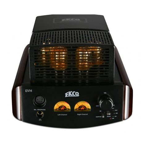
ekco Eva User manual

EVA
INTEGRATED AMPLIFIER
EVA

Read these instructions.
Keep these instructions.
Heed all warnings.
Follow all instructions.
Do not use this apparatus near water.
Clean only as recommended in these instructions.
Do not block any ventilation openings.
Install in accordance with the manufacturer's instructions.
Do not install near any heat sources such as radiators, heat
registers, stoves, or other apparatus(including ampliers) that
produce heat.
Do not defeat the safety purpose of the polarized or grounding
type plug. A polarized plug has two blades with one wider
than the other. Agrounding type plug has two blades and a
provided for your safety. If the provided plug does not fit into your
outlet, consult an electrician for replacementof the obsolete outlet.
Protect the power cord from being walked on or pinched,
particularly at plugs, convenience receptacles, and the point
where they exit from the apparatus.
Use only attachments/accessories specied by the
manufacturer.
Use only with a cart, stand, tripod, bracket, or table
specied by the manufacturer, or sold with the
apparatus. When a cart is used, use caution when moving the
cart/apparatus combination to avoid injury from tip-over.
Unplug this apparatus during lightning storms or when unused
for long periods of time.
Refer all servicing to qualied service personnel. Servicing is
required when the apparatus has been damaged in any way,
such as power-supply cord or plug is damaged, liquid has been
exposed to rain or moisture, dose not operate normally, or has
been dropped.
Warning:To reduce the risk of re or electrical shock, do not
be exposed to dripping and splashing and no object filled with
liquids such as a vase of flowers should be placed on the product.
No naked flame sources such as candles should be placed on the
product.
Warning:e Mains plug is used as disconnect shall remain
readily operable.
Caution: Changes or modifications not expressly approved by the
manufacturer could void the user's authority to operate this device.
is equipment has been tested and found to comply with
the limits for a Class B digitial device, pursuant to part 15 of
protection against harmful interference in a residential
frequency energy and, if not installed and used in accordance
with the instructions, may cause harmful interference to radio
or television reception, which can be determined by tuning the
equipment o and on, the user is encouraged to try to correct
the interference by one or more of the following measures:
Re-orientate or re-locate the receiving antenna. Increase the
separation between the equipment and the receiver. Connect
the equipment into an outlet on a circuit dierent from that
to which the receiver is connected. Consult the dealer or an
experienced radio/TV technician for help.
Mains Supply:
panel. If this voltage does not match the mains voltage in your
area, consult your dealer about converting the unit.
IEC mains plug has been removed. In the rare event that it has
broken, check for any obvious cause before replacing the fuse
220-230V (UK,Korea,etc.) T1.6AL 250V Slow Blow
100-120V (USA,Japan,etc.) T3.15AL 250V Slow Blow
IMPORTANT NOTICE TO UK USERS
e appliance cord is terminated with a UK approved mains
plug fitted with a 5A fuse. If the fuse needs to be replaced, an
ASTA or BSI approved BS1362 fuse rated at 5A must be used. If
you need to change the mains plug, remove the fuse and dispose
of this plug safely immediately after cutting it from the cord.
Connecting a Mains Plug
e wires in the mains lead are
coloured in accordance with
th e code: Blue: NEUTRAL
Brown: LIVE: Green and Yellow:
Earth. As these colours may
not correspond to the coloured
markings identifying the terminals
in your pulg, proceed as follows:
e BLUE wire must be connected to the terminal marked
wire must be connected to the terminal marked with letter L or
coloured BROWN or RED.
e GREEN & YELLOW wire must be connected to the
terminal marked with the letter E or coloured GREEN or
GREEN & YELLOW or marked with the Earth Symbol .
Protective earthing terminal. e apparatus should be
connected to a mains socket outlet with a protective earthing
connection.
voltages. DO NOT remove covers or dismantle.
BATTERY WARNING:e handset uses two AAA batteries.
ere is a risk of re and burns if the batteries are handled
improperly. Do not disassemble, crush, puncture, short external
contacts, or dispose of in fire or water. Do not attempt to open
batteries.
When the handset operation becomes erratic: replace the
batteries with a pair of new batteries of the same type and
construction.
Discard used batteries in accordance with recycling regulations in
force in your area.
Warning:
not be exposed to excessive heat such as sunshine, fire or the like.
and maintenance instructions in the literature
accompanying this unit.
is symbol indicates that dangerous voltage
constituting a risk of electric shock is present
within this unit.
IMPORTANT SAFETY INFORMATION

EKCO
EVA
CONTENTS
INTRODUCTION …………………………………………………………………………………………………… 4
PRELIMINARIES …………………………………………………………………………………………….………… 4
MAINS SUPPLY ………………………………………………………………………………………….……………. 4
INSTALLATION ……………………………………………………………………………………………...........… 5
OPERATION …………..............………………………………………………………………………………....…… 6
CONNECTIONS ………...........................……………………………………………………….………..…….……
FURTHER INFORMATION ………...........................…………………………………………………………….... 7
USING THE USB SOURCE ……………………………………………………………………............……….……7
SPECIFICATIONS …………………………………………………………………………………….………….......... 8
6

4
INTRODUCTION
PRELIMINARIES
·One EKCO EVA
·One IEC mains lead tted with an appropriate mains connector
·220-240V T1.6A 20MM
·100-120V T3.15A 20MM
Instruction Manual and Warranty Registration form
·
One set of packing materials
·
Consult the dealer from whom you purchased the equipment if any items are missing.
Please retain the packing material for future transportation of the product.
Please read this manual in full before installing your new amplifier and retain the manual and your purchase
receipt for future reference.
EVA INTEGRATED AMPLIFIER
MAINS SUPPLY
e EKCO EVA is designed for the music lover. We make no exaggerated performance claims and are
content to let the results speak for themselves. ank you for purchasing this EKCO equipment. We hope
that it will bring you many years of listening pleasure, and that, like its illustrious predecessor, it will be
a treasured possession for you and for future generations of music lovers .
e mains operating voltage of the unit is indicated on the rating plate attached to the unit. If this voltage
does not match the mains voltage in your area, consult your EKCO dealer about converting the unit. e
fuse rating should be:
e EKCO EVA carton contains:
EVA

5
INSTALLATION
Place the unit on a stable rigid surface with at least 1m (3ft) of free space above it. If you are using a
turntable, ensure that the tonearm / preamplifier combination is least 400mm away from the amplifier
to minimize any hum conduction and ideally on a separate shelf. If you have to use the turntable and the
amplifier on the same surface, place the turntable to the right of the amplifier to maximize the distance
between the tonearm and the amplifier.
Do not use this amplifier in a confined space or an enclosed cabinet!
Avoid placing the amplifier in front of loudspeakers to avoid vibrations from the speaker drive units causing
microphonics in the amplifier and degrading the sound.
If this is your first valve amplifier: please familiarise yourself with some important issues surrounding
the safe use of your amplifier.
Valve power amplifiers generate a lot of heat even with no input so it is vital to ensure adequate ventilation
for your amplifier.
Although the protective cages over the valves get hot they are very unlikely to cause a burn. For absolute
safety the units should be placed out of the reach of children and pets and away from heat-sensitive objects.
Valves require a high voltage to function. Do not open the case. Also ensure that nothing is poked, dropped
or poured into the amplifier’s case.
e environment should be dry and free from litter. Do not place magnetically or thermally sensitive
objects (i.e. credit cards or optical disc) close to the unit.
Because valves are constructed from fine wires and tiny metal parts they can pick up external vibrations. If
you place the power amplifier too close to speakers, direct sound at high volumes may vibrate the valves. 1
meter (3ft) to the side of each speaker should be considered a sensible minimum.
e signal inputs to the amplier are via RCA phono connectors. As valve equipment works at high
impedances, the phono interconnects from source unit should be well screened and of low-noise, low-
capacitance construction. To minimize capacitance and other eects, signal interconnectors should be kept
as short as possible.
Choose good quality loudspeaker cable designed for the purpose rather than general purpose ‘zip’ or ‘bell’
inductance or capacitance cables as these can degrade the sound when using a valve output stages.
is amplier requires connection to an earthed (grounded) mains supply. In your sound system, the
amplifier should be the only device connected to mains ground to negate hum induced by ground loops.
For this reason we suggest that you avoid using interconnectors with separate ground wires. If any of your
other equipment is grounded a 'hum loop' may arise. If this happens please consult your dealer for
advice.
Valves Get Hot
Valve Amplifiers Work at High Voltages
Valves are Microphonic
Interconnects and Cables
Mains Earthing (Grounding)

Rotate the input selector left or right to select the Input. e input indicator shows the selected input.
Remember to turn the main system volume control to minimum when changing inputs or when changing
discs, and especially when cleaning your stylus.
6
OPERATION
Switching On
Front Panel
CONNECTIONS
Rear Panel
Select the Negative Feedback level .
Turn the volume control fully anticlockwise to its minimum setting (0).
Switch the ON/OFF switch to‘1’to switch the amplier ON.
Selecting an Input
EVA
Left Wattmeter
Display
Right Wattmeter
Display
Volume Control
NF
Select
Headphone
Output
Input Select
AUX Input Digital Input L/R Speaker Terminal
BT Antenna
Mains Input
Mains
Fuse Holder
Mains Switch

7
FURTHER INFORMATION
With the increased popularity of computers as source, this EVA USB D/A converter allows consumers to
enjoy listening to digital music sources from a computer (Windows or Mac) via USB connection. is
product is USB 1.1 and 2.0 compliant.is device supports sampling frequencies ranging from 35kHz to
384kHz(supports DSD64, DSD128, DSD256)and incorporates a high quality digital-to-analogue
converter (DAC). e factory default is 48kHz input sampling frequency. With the computer in operation
the EVA USB DAC will detect input data.
Note: Windows does not support 192kHz sampling frequency. Owners of computers (Windows) are
required to install corresponding software provided in the accompanying CD-ROM. Simply follow the
software installation instructions contained.
USING THE USB SOURCE
Burn in is very important. Valve components work at high voltage and temperature and when new they
should spend an extended period at those temperatures to bed in. We recommend you burn in the amplier
for at least four or preferably twelve hours before you rst use it for serious listening. If you run in your
equipment for this extended period, make doubly sure that all the safety conditions covered in this manual
are fully met. Supervise the equipment for the rst hour or so and if you have to leave the unit unattended
thereafter, look in occasionally to make sure all is well.
Burn In New Equipment
Allow at least fteen minutes for the amplier to 'warm up' before use. If you play loud music while the
system is cold, the output valves will not be fully operational and the amplier will be starved of voltage and
current. e resulting distortion is unpleasant and can result in potential damage to the amplier's valves and
your loudspeakers. Intensive use of the equipment before it has warmed up will shorten a valve's life.
Warming Up Before Use
Valves contain a heating element. is heats up the valve's cathode, which is coated to give o a steady
stream of electrons. After a few years this coating will begin to wear out and performance will gradually
deteriorate. e EL84 output valves are likely to deteriorate rst but the driver valves will also eventually
wear out.
As the valves start to wear out the sound will become less well dened and a lack of dynamics and power will
become evident. Replacing the valves with a new set will fully restore the audio performance of the amplier.
When replacing valves it is essential to use the highest quality available. Poor quality valves will adversely
aect the sound quality and may in extreme cases damage the amplier. When replacing the output valves,
use matched sets for best results.
Do not leave the amplier permanently switched on or you will seriously shorten the lifespan of your valves!
Valve Lifetimes
After installing or changing the wiring to your speakers, keep the volume control at zero, let the amplier
warm up and turn up the main volume gradually. If you don't hear sound, switch o immediately and
investigate.
e output transformer is designed to match the high voltage, low current conditions in which the output
valves operate to the low voltage, high current requirements of a loudspeaker. Although robust, an output
transformer can be damaged and, in extreme cases, wrecked by careless use. If you play a valve amplier into
a short circuit, the output transformer will soak up a lot of energy before failing, but if the short persists the
transformer could be damaged. Operating a valve amplier at high output level without a loudspeaker
connected can also damage an output transformer.
is amplier must be used with a load connected load conditions, otherwise it may cause damage to the
output transformer.
Output Transformer

8
SPECIFICATIONS
IAG House, 13/14 Glebe Road, Huntingdon, Cambridgeshire, PE29 7DL, UK.
International Service Centre
throughout the EU. To prevent possible harm to the environment or human health from uncontrolled waste disposal, recyle
it responsibly to promote the sustainable reuse of a material resources. To return your used device, please use the return and
recycling.
*IAG reserves the right to adjust the specifications and performance without notice.
Model :
Output Power :
Frequency Response :
Input Sensitivity :
S/N Ratio :
Input Impedance :
Channel Seperation :
THD :
Vacuum Tubes :
Inputs :
Digital Input Sampling Frequencies :
Dimension (H x W x D) :
Net Weight :
EVA
2 x 15W RMS(6Ω)
2 x 12W RMS(8Ω)
20Hz~20KHz +/-1dB
150mV RMS for full output
>90dB(ref. rated output)
100K Ohms
65dB (1kHz)
<0.5% (1KHz at rated output)
V1..................1×ECC83
V2 - V3..........2×ECC82
V4 - V7............ 4×EL84
1 x RCA input 1 x Coaxial input 1 x Optical input
1 x USB input 1xBluetooth(aptX®) input
44.1kHz 48kHz 88.2kHz
96kHz 176.4kHz 192kHz
USB(DSD256 PCM384kHz)
180 X 220 X 300 (mm)
7.2kg


IAG House, 13/14 Glebe Road, Huntingdon, Cambridgeshire, PE29 7DL, UK
Tel: + 44 (0) 1480 452561 Fax: + 44 (0) 1480 413403
IAG reserves the right to alter the design and specifications without notice. All rights reserved © IAG Group Ltd.
Ekco is a member of the International Audio Group. CODE: EH14-MNL001a
Table of contents
Other ekco Amplifier manuals
Popular Amplifier manuals by other brands

Schwaiger
Schwaiger GHSA0100 USER GUIDE AND SAFETY INSTRUCTIONS

Dynavector
Dynavector P-75 Instructions and specifications
Adcom
Adcom GFP-555II owner's manual
ALLNIC AUDIO
ALLNIC AUDIO HPA-5000 XL owner's manual

Sony
Sony XM-754SX Primary Service manual

Technics
Technics SU-7300 - service operating instructions


