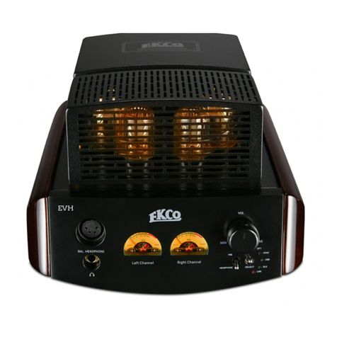
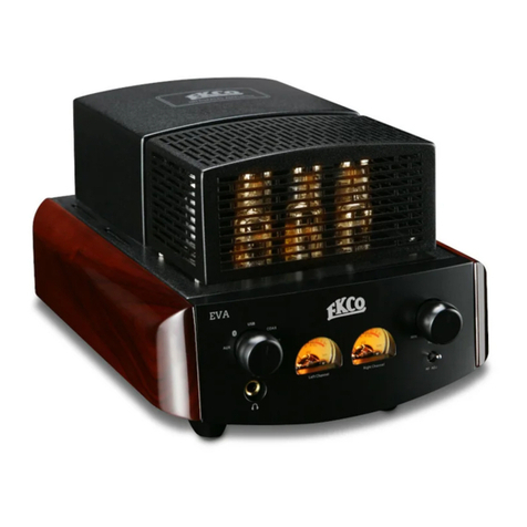
ekco EV55SE User manual

C
M
Y
CM
MY
CY
CMY
K
EKCO Manual-1.pdf 2009-11-25 9:58:33

IMPORTANT SAFETY INFORMATION Caution: Changes or modifications not expressly approved by the
manufacturer could void the user's authority to operate this device.
This equipment has been tested and found to comply with the limits
for a Class B digitial device, pursuant to part 15 of the FCC rules. These
limits are designed to provide reasonable protection against harmful
interference in a residential installation. This equipment generates,
uses and can radiate radio frequency energy and, if not installed and
used in accordance with the instructions, may cause harmful
interference to radio or television reception, which can be
determined by tuning the equipment off and on, the user is
encouraged to try to correct the interference by one or more of the
following measures:
Re-orientate or re-locate the receiving antenna. Increase the
separation between the equipment and the receiver. Connect the
equipment into an outlet on a circuit different from that to which the
receiver is connected. Consult the dealer or an experienced radio/TV
technician for help.
Mains Supply: The mains operating voltage is shown on the rear
panel. If this voltage does not match the mains voltage in your area,
consult your dealer about converting the unit.
The mains supply fuse on the rear panel is accessible when the IEC
Read these instructions. mains plug has been removed. In the rare event that it has broken,
check for any obvious cause before replacing the fuse with one of the
Keep these instructions.
correct rating and type. The fuse values are:
Heed all warnings.
220 - 240V (UK, Korea, etc.) T4.0AL 20mm Slow Blow
Follow all instructions.
100 - 120V (USA, Japan, etc) T 10.0AL 20mm Slow Blow
Do not use this apparatus near water.
IMPORTANT NOTICE TO UK USERS
Clean only as recommended in these instructions.
The appliance cord is terminated with a UK approved mains plug
Do not block any ventilation openings.
fitted with a 5A fuse. If
Install in accordance with the manufacturer's instructions.
Do not install near any heat sources such as radiators, heat registers,
stoves, or other apparatus (including amplifiers) that produce heat.
Do not defeat the safety purpose of the polarized or grounding type
plug. A polarized plug has two blades with one wider than the other.
A grounding type plug has two blades and a third grounding prong.
The wider blade or the third prong are provided for your safety. If the
provided plug does not fit into your outlet, consult an electrician for
replacement of the obsolete outlet.
Protect the power cord from being walked on or pinched,
particularly at plugs, convenience receptacles, and the point where
they exit from the apparatus.
Use only attachments/accessories specified by the
manufacturer.
Use only with a cart, stand, tripod, bracket, or table
specified by the manufacturer, or sold with the
apparatus. When a cart is used, use caution when moving the
cart/apparatus combination to avoid injury from tip-over.
Unplug this apparatus during lightning storms or when unused for
long periods of time. CAUTION: This appliance operates on very high
Refer all servicing to qualified service personnel. Servicing is required voltages. DO NOT remove covers or dismantle. This
when the apparatus has been damaged in any way, such as power- is very dangerous and could cause severe shock.
supply cord or plug is damaged, liquid has been spilled or objects BATTERY WARNING: The handset uses two AAA batteries. There is a
have fallen into the apparatus, the apparatus has been exposed to risk of fire and burns if the batteries are handled improperly. Do not
rain or moisture, does not operate normally, or has been dropped. disassemble, crush, puncture, short external contacts, or dispose of
Warning: To reduce the risk of fire or electrical shock, do not expose in fire or water. Do not attempt to open batteries.
this product to rain or moisture. The product must not be exposed to When the handset operation becomes erratic: replace the
dripping and splashing and no object filled with liquids such as a batteries with a pair of new batteries of the same type and
vase of flowers should be placed on the product. construction.
No naked flame sources such as candles should be placed on the Discard used batteries in accordance with recycling regulations in
product. force in your area.
the fuse needs to be replaced, an ASTA or BSI
approved BS1362 fuse rated at 5A must be used. If you need to
change the mains plug, remove the fuse and dispose of this plug
safely immediately after cutting it from the cord.
Connecting a Mains Plug
The wires in the mains lead are
coloured in accordance with the
code: Blue: NEUTRAL Brown: LIVE:
Green and Yellow: Earth. As these
colours may not correspond to the
coloured markings identifying the
terminals in your plug, proceed as
follows:
The BLUE wire must be connected to the terminal marked with the
letter N or coloured BLUE or BLACK. The BROWN wire must be
connected to the terminal marked with the letter L or coloured
BROWN or RED.
The GREEN & YELLOW wire must be connected to the terminal
marked with the letter E or coloured GREEN or GREEN & YELLOW or
marked with the Earth Symbol .
CAUTION!
RISK OF ELECTRIC SHOCK
DO NOT OPEN
AVERTISSEMENT: RISQUE DE CHOC ELECTRIQUE-
NE PAS OUVRIR
TO REDUCE THE RISK OF ELECTRIC SHOCK DO NOT REMOVE COVER (OR BACK)
NO USER-REMOVEABLE PARTS INSIDE
REFER SERVICING TO QUALIFIED PERSONNEL
This symbol indicates that there are important operating
and maintenance instructions in the literature
accompanying this unit.
This symbol indicates that dangerous voltage constituting
a risk of electric shock is present within this unit.
GREEN
&
YELLOW
(EARTH)
BLUE
(NEUTRAL) (LIVE)
BROWN
FUSE


INSTALLATION
Place the unit on a stable rigid surface with at least 1m (3ft.) of free space above it. If you are
using a turntable, ensure that the tonearm/preamplifier combination is least 400 mm away
from the amplifier to minimise any hum conduction and ideally on a separate shelf. If you
have to use the turntable and the amplifier on the same surface, place the turntable to the
right of the amplifier to maximise the distance between the tonearm and the amplifier.
Do not use this amplifier in a confined space or an enclosed cabinet!
Avoid placing the amplifier in front of the loudspeakers to avoid vibrations from the speaker
drive units causing microphonics in the amplifier and degrading the sound.
If this is your first valve amplifier: please familiarise yourself with some important issues
surrounding the safe use of your amplifier.
Valves Get Hot
Valve power amplifiers generate a lot of heat even with no input so it is vital to ensure
adequate ventilation for your amplifier.
Although the protective cages over the valves get hot they are very unlikely to cause a burn.
For absolute safety the unit should be placed out of the reach of children and pets and away
from heat-sensitive objects.
Valve Amplifiers Work at High Voltages
Valves require a high voltage to function. Do not open the case. Also ensure that nothing is
poked, dropped or poured into the amplifier's case.
The environment should be dry and free from litter. Do not place magnetically or thermally
sensitive objects (i.e. credit cards or optical discs) close to the unit.
Valves are Microphonic
Because valves are constructed from fine wires and tiny metal parts they can pick up
external vibrations. If you place the power amplifier too close to the speakers, direct
sound at high volumes may vibrate the valves. 1 metre (3ft) to the side of each speaker
should be considered a sensible minimum.
Interconnects and Cables
The signal inputs to the amplifier are via RCA phono connectors. As valve equipment works
at high impedances, the phono interconnects from source unit should be well screened
and of a low-noise, low-capacitance construction. To minimise capacitance and other
effects, signal interconnects should be kept as short as possible.
Choose good quality loudspeaker cable designed for the purpose rather than general
purpose ‘zip’ or ‘bell’ wire. The cable should be of adequate gauge to maximise bass
performance. We do not recommend high inductance or capacitance cables as these can
degrade the sound when using a valve amplifier output stages.
Mains Earthing (Grounding)
This amplifier requires connection to an earthed (grounded) mains supply. In your sound
system, the amplifier should be the only device connected to mains ground to negate hum
induced by ground loops. For this reason we suggest that you avoid using interconnects
with separate ground wires. If any of your other equipment is grounded a “hum loop” may
arise. If this happens please consult your dealer for advice.
4

Before connecting your amplifier all components in the system must be unplugged
at the mains and the volume control of the amplifier set at zero.
Connecting Signal Inputs
Virtually any line level audio source component may be connected to the signal inputs.
These include tuners, CD players etc. The inputs are all electrically identical and are named
purely for ease of recognition.
Connect a pair of high quality screened cables terminated in RCA phono plugs from the
LINE OUTPUT of the source component to the chosen input of the amplifier.
When making stereo connections, RCA plugs and sockets coded white or black usually
indicate the LEFT channel and those coded red the RIGHT channel. In a stereo pair of
sockets the upper socket is usually the Left Channel and the lower socket the Right. If you
are in any doubt, consult a qualified dealer.
How to Connect a Loudspeaker Terminal
Strip any outer sleeve from the loudspeaker cable
to a depth of around 40 mm (1.5”).Strip the top
7mm of sleeving to expose the bare wire. If you are
using stranded cable, lightly twist the strands to
gather any loose ends.
Partially unscrew the terminal to expose the cross
hole at the terminal base. Push the bare end of the
cable into the hole. Ensure that the polarity is
correct and there are no loose strands which
could touch adjacent terminals. Tighten securely.
Fused IEC
Mains Input
Ground
Loudspeaker Connections
Right Speaker Left Speaker
CONNECTIONS
5
Signal Inputs
Aux Tape Tuner
Disc2Disc1
Ch. A Ch. B Ch. B Ch. A ON/OFF
Switch

Standard Wiring
The main loudspeakers should be connected to the “A” terminals. Connect the Left
Loudspeaker to the Left channel of the amplifier. Connect the Red (Positive) terminal of
the loudspeaker to the +VE terminal of the amplifier. Connect the Black (Negative)
terminal of the loudspeaker to the –VE terminal of the QUAD II Classic Integrated
amplifier. Now connect the Right Loudspeaker to the Right channel of the amplifier.
Ensure that the Left and Right loudspeakers are connected to the Left and Right
channels respectively.
If you have another pair of loudspeakers in a different location you can connect them to
the “B” terminals.
Bi-Wiring
Connecting the Mains
Set the ON/OFF switch on the rear panel to the “0" OFF position.
Ensure that the volume control on the front panel is at the minimum (fully anticlockwise)
position.
Plug the supplied IEC lead into the mains input socket.
Now plug the IEC lead into the wall socket and switch on at the mains point.
Plug in the mains leads and switch on the power to your source units. The system is now
fully connected and ready for operation.
Bi-wiring is a technique whereby the treble and bass sections of a loudspeaker are
independently connected to the relevant channel of the amplifier. If your loudspeakers can
be bi-wired, you may certainly bi-wire the amplifier to the loudspeakers if you wish. Follow
the recommendations in your loudspeaker user handbook.
6
RIGHT
SPEAKER
LEFT
SPEAKER
To “Speakers B”
RIGHT
SPEAKER
LEFT
SPEAKER
To “Speakers B”

Switching On
Select an operating mode (Triode or Ultra Linear)
Select the Negative Feedback level (Min or Max)
Select a pair of loudspeakers (A or B)
Turn the volume control fully anticlockwise to its minimum setting (0).
Switch the ON/OFF switch to“I”to switch the amplier ON.
The power Indicator will light up.
Warming Up
Allow at least fteen minutes for the amplier to 'warm up' before use.Warming up should
always be done with the amplier volume control at zero. After the amplier has warmed
up fully, the system is ready for use.
Selecting an input
Move the Input selector to the left or the right to select the phono or a regular line input.
The input indicator indicates the selected input.
Remember to turn the main system volume control to minimum when changing inputs or
when changing discs, and especially when cleaning your stylus.
Changing Loudspeakers
Turn the volume control to minimum and then switch the Speaker Selector from A to B or
vice versa to change loudspeakers. Turning the volume down is very important if you are
changing the output from a low sensitivity loudspeaker to one of high sensitivity.
Changing the Mode and Negative Feedback (NFB) Settings
Turn the Volume control to minimum, switch the amplier o and wait a few seconds. Now
you may change either or both settings and switch power on again.
Fora full technicalexplanation of these settingsplease refer to Page 10
Altering the volume
Turn the volume control up to a moderate level. Remember the position of the volume
control is NOT an indication of“how loud”your system will play.
DO NOT switch the operating mode or alter the NFB settings when the amplier is
switched on.
OPERATION
7
Volume
Control
Input
Selector
Speaker
Selector Mode
Select NF
Select
IR
Receiver

THE REMOTE HANDSET
Installing Handset Batteries
Remove the bottom cover of the handset. The batteries sit in a
cradle in the handset. Carefully lift up the cradle making sure not to
damage the connecting wires. Place two AAA batteries in the
cradle and then return the cradle to the handset. The batteries
should be inserted with the polarities as shown in the drawing and
the cradle should be inverted (ie with the batteries facing down)
Now replace the cover
Point the handset away from the amplifier and press a button. the
indicator on the handset will flash if the batteries are correctly
connected.
Adjusting the Volume with The Handset
Point the handset directly at the amplier front panel. Press the Volume +/– buttons to
increase or decrease the volume.
Muting the Volume
Point the handset directly at the amplier front panel. Press the Mute button. The amplier
volume will be muted. Press the mute button again to restore the volume.
After Use
Turn the Volume control down and then switch the amplier o.
Mute Button
Volume UP Button
Volume Down Button
Indicator Light
8

FURTHER INFORMATION
Running In New Equipment
Running in is very important. Valve components work at high voltages and temperatures
and when new they should spend an extended period at those temperatures to bed in.
We recommend you run the amplifier in for at least four and preferably twelve hours
before you first use it. If you run in your equipment for this extended period, make doubly
sure that all the safety conditions covered in this manual are fully met. Supervise the
equipment for the first hour or so and if you have to leave the unit unattended thereafter,
look in occasionally to make sure all is well.
Warming Up Before Use
Allow at least fifteen minutes for the amplifiers to 'warm up' before use. If you play loud
music while the system is cold the output valves will not be fully operational and the
amplifier will be starved of voltage and current. The resulting distortion is unpleasant
and potentially damaging to the amplifiers' valves and your loudspeakers. Intensive use
of the equipment before it has warmed up will shorten valve life.
Valve Lifetimes
Valves contain a heating element. This heats up the valve's cathode, which is coated to
give off a steady stream of electrons. After a few years this coating will begin to wear out
and performance will gradually deteriorate. the KT66 output valves are likely to
deteriorate first but the driver valves will also eventually wear out.
As the valves start to wear out the sound will become less well defined and a lack of
dynamics and power will become evident. Replacing the valves with a new set will fully
restore the audio performance of the amplifier. When replacing valves it is essential to
use the highest quality available. Poor quality valves will adversely affect the sound
quality and may in extreme cases damage the amplifier. When replacing the output
valves, use matched sets for best results.
Do not leave the amplifiers permanently switched on or you will seriously shorten the
lifespan of your valves!
Output Transformer
After installing or changing the wiring to your speakers, keep the volume control at zero,
let the amplifier warm up and turn up the main volume gradually. If you don't hear
sound, switch off immediately and investigate.
The output transformer is designed to match the high voltage, low current conditions in
which the output valves operate to the low voltage high current requirements of a
loudspeaker. Although robust, an output transformer can be damaged and, in extreme
cases wrecked, by careless use. If you play a valve amplifier into a short circuit, the
output transformer will soak up a lot of energy before failing, but if the short persists the
transformer could be damaged.
Operating a valve amplifier at high output levels with no loudspeaker connected can
also damage an output transformer.
Never operate the amplifier with the Speaker A/B switch set to a position where
no speakers are connected.
Overall Volume Levels
Output levels from different source components in a high fidelity system can vary
widely. A CD player can produce levels significantly higher (>18 dB ) than an FM tuner. It
follows that the position of the volume control is not a guide as to 'how loud' the
equipment will go. Though the overload characteristics of the amplifier are such that
you can play your music at surprisingly high levels, if the sound is distorted, you are
overloading your equipment whatever the position of the volume control.
9

Valve Types
A triode valve has three elements The Anode and Cathode are
connected between the Power supply and Ground. When an input
is applied to the Control Grid, the amplified output appears at the
anode.
Triodes are linear and robust but their amplification factor is low
which makes them inefficient and limits their output power.
To overcome this drawback an extra grid is added. This greatly
increases the amplification factor and so the efficiency of the valve
and makes large outputs a reality. The drawback is that
these valves are inherently non-linear and their distortion is high.
Triode and Beam Tetrode Output Stages
High power valve output stages are push pull. In this design the input signal is split into
two halves via a phase splitter. Each half of the signal goes to one output valve and the
signal is combined in the output transformer which is then coupled to the loudspeaker.
The triode push-pull output stage is the choice of
many audio purists. The drawback is that because
triodes are inefficient the output is limited and
insufficient to drive many modern low sensitivity
loudspeakers to high volumes.
A basic diagram of our triode output stage is given
here. By connecting the screen grid to the anode a
beam tetrode valve effectively becomes a triode with
all its benefits and drawbacks.
For many years the beam tetrode output stage was
relegated to public address amplifiers because of its
inherent non linearity and high distortion. Many
attempts were made to improve tetrode operation
(notably by Quad with their cathode-coupled design)
but their output transformers are complicated and
very expensive to manufacture.
Enter the Ultra Linear output stage. By connecting
the screen grid to a special tapping on the output
transformer a local feedback loop is incorporated
around the output valves, lowering their output
impedance, linearising the output and massively
reducing distortion. The result is an amplifier with
most of the advantages of the triode combined with
the efficiency and power of a multi-grid valve.
Negative Feedback (NFB)
Overall Negative Feedback (NFB) is a process where a percentage of the output of an
amplifier is fed back in reverse (negative) phase. This lowers the output
impedance, reduces distortion and improves frequency response. The amplifier has better
control over the loudspeaker and a flatter frequency response and lower distortion bring
obvious benefits. However valve amplifiers have output transformers and valves are high
impedance devices High levels of NFB may at high frequencies in extreme cases (especially
with awkward loudspeakers) cause instability. Long before instability arises however the
listener can experience discomfort - a phenomenon known as listener fatigue.
In our amplifier you may select low or high NF . Our amplifier is inherently stable so if you
have, for example, horn loudspeakers you may find that triode operation with low NFB is
the way to go. With conventional loudspeakers (especially low sensitivity designs) you may
find that Ultra linear operation with high NFB offers the best operating mode.
We feel it is preferable to have a relaxed generous sound stage which you can enjoy over
long periods than a ruler-flat response which may become tiring to listen to over time.
Experiment with different sources at different volume levels. Allow a generous time period
to elapse before changing modes and then use the one which offers you the best result.
power
to the input
ANODE
CATHODE
CONTROL GRID
ANODE
CATHODE
CONTROL GRID
SCREEN GRID
10
+DC
NFB
INPUT
KT88/6550
KT88/6550
+DC
NFB
INPUT
KT88/6550
KT88/6550
TRIODE
AMP
U/L
AMP

Care And Cleaning
The surface of the equipment may be cleaned with a damp cloth provided that the power
has been removed Solvent based cleaning materials should never be used as they may
damage the paint If dust accumulates in the slots in the covers, brush them out with a
soft brush before cleaning the unit.
Product Warranty
Your Ekco equipment is guaranteed against any defect in material and workmanship for a
period of one year from the date of purchase with the exception of the valves, which are
warranted for three months. Within the warranty period we will undertake replacement of
defective parts free of charge provided that the failure was not caused by misuse, accident
or negligence. Your statutory rights within the territory in which you purchased the
equipment are not ected by this warranty.
If your equipment requires servicing (including valve replacement) you should return it to
the dealer from whom the equipment was purchased.
If you are abroad and there is no suitable dealer in your area, please contact the distributor
for the country in which it was purchased.
It is user's responsibility to ensure that all equipment for service is returned carriage paid
and in the original packaging. Enclose a brief note with your name and address and the
reason for returning the equipment.
International Service Centres
UK: International Audio Group Service Centre, Unit 4, St Margaret’s Way, Stukeley Meadows
Industrial Estate Huntingdon, Cambs, PE29 6EB
Tel:+44 (0)1480 447700 Fax: +44 (0)1480 431767
Asia: IAG Sales and Service Centre, Jiuwei Village, XixiangTown, Shenzhen, China 518102.
Tel: +86-755-27484491 Fax:+86-755-29651484
Specifications
Valves: 4 x KT88: 1 x 12AX7: 4 x 12AU7
Output Power:
THD :
Hum and Noise:
Dimensions: (D) 410mm x (W ) 350mm x (H) 190mm
GrossWeight: 28kg
IAG reserves the right to adjust the and performance from time to time.
Service Information
Ultralinear Mode: 55w/8Ω
Triode Mode: 28w/8Ω
Input
Frequency response: 20Hz to 30KHz±1dB
Sensitivity: Ultralinear Mode: 300mV RMS for 55w/8Ω (Max FB)
Triode Mode: 300mV RMS for 28w/8Ω (Max FB)
<1% at 1kHz (Ultralinear Mode / Triode Mode )
Ultralinear Mode: >90dB 55w/8Ω (Max FB)
Triode Mode: >90dB 28w/8Ω (Max FB)
11

Other manuals for EV55SE
1
Table of contents
Other ekco Amplifier manuals
Popular Amplifier manuals by other brands
Schiit
Schiit Freya owner's manual
KV2 Audio
KV2 Audio VHD3200 Operator's manual

AUSTRALIAN MONITOR
AUSTRALIAN MONITOR ISP Series Installation and operation manual

Rotel
Rotel 2-Channel Power Amplifier RB-1510 owner's manual
Hama
Hama PA-005 operating instructions
Acoustic Image
Acoustic Image Clarus 2R owner's manual

