EKF Electronik CV1-AMBIENT Manual

Technical Information
CV1-AMBIENT • Dual-Screen CPCI Graphics Adapter
Document No. 2513 • Edition 1
2001-11

Technical Information CV1-AMBIENT • CPCI Graphics Adapter
- 2 -
EKF Elektronik GmbH * Philipp-Reis-Str. 4 * D-59065 HAMM (Germany)
Tel. +49 (0)2381/6890-0 * Fax. +49 (0)2381/6890-90 * E-Mail [email protected] * Internet http://www.ekf.de
Contents
AboutthisManual....................................................... 3
EditionHistory..................................................... 3
Nomenclature ..................................................... 3
TradeMarks ...................................................... 3
Legal Exclaimer - Liability Exclusion ..................................... 3
CV1-AMBIENTFeatures ................................................... 4
ShortDescription................................................... 4
FeatureSummary .................................................. 6
BlockDiagram..................................................... 7
ComponentAssembly ............................................... 8
InstallingandReplacingComponents......................................... 9
BeforeYouBegin................................................... 9
Warnings ................................................... 9
Caution .................................................... 9
InstallingtheBoard................................................ 10
RemovingtheBoard ............................................... 11
EMCRecommendations............................................. 12
Technical Reference - Jumper Fields and Connectors ............................. 13
Caution......................................................... 13
JumperFields .................................................... 13
JumperFieldsDispConfAandDispConfB........................... 13
DispConfA ................................................. 13
DispConfB ................................................. 14
Jumper EnaI2C .............................................. 15
JumperSelectLower.......................................... 15
PrimaryDisplayPort-DVI-IReceptacle.................................. 16
Secondary Display Port - D-SUB 15-Pos. Connector ........................ 17
VideoOutputs.................................................... 18
S-VideoOutput ............................................. 18
CompositeVideoOutput ...................................... 18
ZoomVideoPort.................................................. 19
BIOSSocket...................................................... 20
CompactPCI Connector J1 ........................................... 21
BoardIdentification ..................................................... 22

Technical Information CV1-AMBIENT • CPCI Graphics Adapter
- 3 -
EKF Elektronik GmbH * Philipp-Reis-Str. 4 * D-59065 HAMM (Germany)
Tel. +49 (0)2381/6890-0 * Fax. +49 (0)2381/6890-90 * E-Mail [email protected] * Internet http://www.ekf.de
About this Manual
This manual is a short form description of the technical aspects of the CV1-AMBIENT, required
for installation and system integration. It is intended for the very advanced user only.
Edition History
EKF
Document Ed. Contents/Changes Author Date
Text # 2513
cv1tie.wpd 1 1. Edition Technical Information CV1-
AMBIENT, English, preliminary edition, to
be completed later on, valid for board
revision 1
jj 9 November
2001
Nomenclature
Signal names used herein with an attached '#' designate active low lines.
Trade Marks
Some terms used herein are property of their respective owners, e.g.
Pentium, Celeron, Socket 370: ® Intel
CompactPCI
: ® PICMG
Windows 98, Windows NT, Windows 2000: ® Microsoft
EKF does not claim this list to be complete.
Legal Exclaimer - Liability Exclusion
This manual has been edited as carefully as possible. We apologize for any potential mistake.
Information provided herein is designated exclusively to the proficient user (system integrator,
engineer). EKF can accept no responsibility for any damage caused by the use of this manual.

Technical Information CV1-AMBIENT • CPCI Graphics Adapter
- 4 -
EKF Elektronik GmbH * Philipp-Reis-Str. 4 * D-59065 HAMM (Germany)
Tel. +49 (0)2381/6890-0 * Fax. +49 (0)2381/6890-90 * E-Mail [email protected] * Internet http://www.ekf.de
CV1-AMBIENT
CV1-AMBIENT Features
Short Description
The CV1-AMBIENT is a universal, dual-screen
3D graphics adapter for use within
CompactPCI
®
systems. Housed on a 3U
Eurocard, the CV1-AMBIENT is equipped
with both, DVI and D-SUB connectors for
simultaneous attachment of digital display
units and analog monitors. The board is built
upon a 128-bit drawing engine, resulting in
superior performance (e.g. playing of DVD
movies with full frame rate). Analog
monitors with a resolution up to 1600x1200
and TFT flat-panel displays up to 1280x1024
pixels are supported by the hardware.
When operated under Windows™, the CV1-
AMBIENT allows for simultaneous use of two
screens. Multi-Display means applications
available at the same time across multiple
display devices, and Dual View is a synonym
for displaying any rectangular portion of the
primary display zoomed up on the secondary
screen.
Drivers are provided for all Windows™
operating systems and Linux. The CV1-
AMBIENT is available with 4..16MB video
memory.

Technical Information CV1-AMBIENT • CPCI Graphics Adapter
- 5 -
EKF Elektronik GmbH * Philipp-Reis-Str. 4 * D-59065 HAMM (Germany)
Tel. +49 (0)2381/6890-0 * Fax. +49 (0)2381/6890-90 * E-Mail [email protected] * Internet http://www.ekf.de
CR9-ADAPT
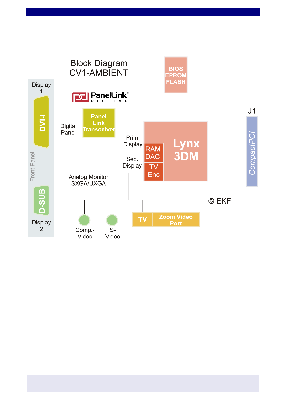
The CV1-AMBIENT is based on the Lynx3DM
(Silicon Motion), a low power high
performance graphics controller chip. The
video memory is integrated into the chip
package (available as 4/8/16MB) and delivers
up to 1.6GB/s bandwidth, resulting in fast
3D rendering, and real-time full frame video
playbackofMPEG2/DVDcontentwithoutthe
need for additional hardware.
The CV1-AMBIENT is suitable for attachment
to all popular video monitors. Displays
provided with a Digital Visual Interface
(typically flat panel TFT style screens) can be
connected to the DVI receptacle (Primary
Display). For all legacy monitors with analog
inputs,the CV1-AMBIENTisprovidedwithan
additional D-SUB connector (Secondary
Display). Both graphics outputs of the CV1-
AMBIENT are independent from each other
and can deliver different content, e.g.
motion video, simultaneously to their
respective screens.
The boards video capture feature processes
incoming video data from the Zoom Video
Port and sends the data to the local frame
buffer. By using a flat ribbon cable, this
interface can be directly connected to the
CP2-HIPHOP (PC Card adapter) or CF4-HIHAT
(IEEE 1394 FireWire host adapter).
Complete OS software support is available
for Linux, Windows™ 98, ME, NT, 2000,
and XP.
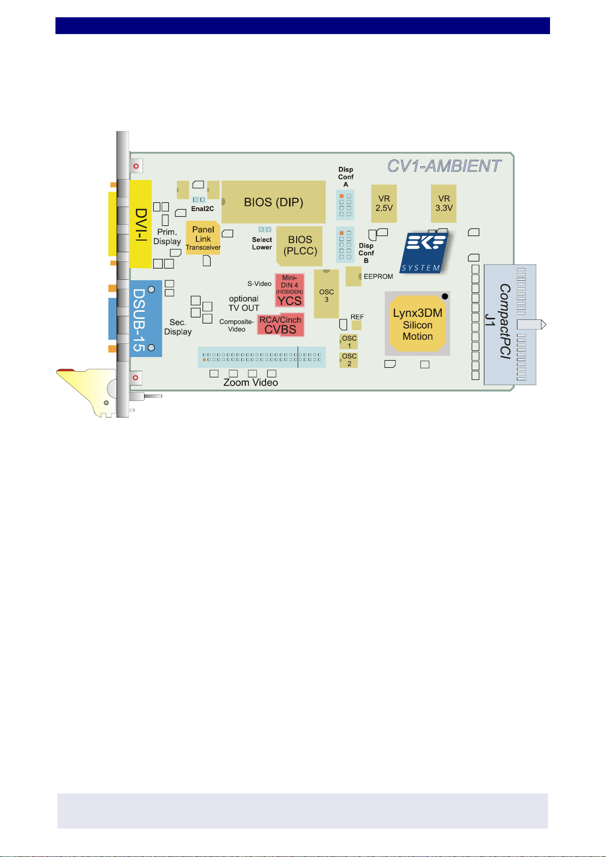
The CV1-AMBIENT is a 3U Eurocard. For use
within 6U CPCI card cages, EKF offers the
CR9-ADAPT, a mechanical kit for the front
panel extension.

Technical Information CV1-AMBIENT • CPCI Graphics Adapter
- 6 -
EKF Elektronik GmbH * Philipp-Reis-Str. 4 * D-59065 HAMM (Germany)
Tel. +49 (0)2381/6890-0 * Fax. +49 (0)2381/6890-90 * E-Mail [email protected] * Internet http://www.ekf.de
Feature Summary
Technical Specifications
Printed
Circuit Board Dimensions 3U Eurocard (100x160mm2), front panel 4HP (20.2mm) EMV
shielded, ejection lever
Graphics Primary Display
Port
Digital Display
Connector
DVI
Supports digital monitors, e.g. TFT flat panel displays, DVI-I 1
receptacle mounted into the boards front panel, up to
1280x1024 pixel, 16M colors, 85Hz refresh rate, interface
electronics based on PanelLink Digital Technology (Silicon
Image), Hot Plug Detection, immunity against noise by
differential signaling according to TMDS (Transition Minimized
Differential Signaling), Single Link.
1Though DVI-I preserves some pins for analog signals, these
pins are NC on the CV1-AMBIENT, resulting in a functionality
identical to DVI-D (D = digital). The DVI-I (I = integrated analog
and digital) receptacle however allows use of both, DVI-I and
DVI-D cables and accessories at your convenience.
Secondary
Display Port
Analog Monitor
Connector D-
SUB15
Supports analog monitors, e.g. multi-sync displays,
SXGA/UXGA compatible, Mini D-SUB 15-pos. socket mounted
into the boards front panel, up to 1600x1200 pixel 2, 16M colors,
85Hz refresh rate, RAMDAC 200MHz
2Currently available Windows™ drivers unfortunately do not
support the maximum resolution
Video Outputs S-Video socket Mini-DIN/Hosiden 4-pos. (S-VHS, Hi-8)3
Composite Video jack Cinch/RCA (CVBS, FBAS)3
3Due to lack of free space in the cards front panel, the video
connectors are mounted in the middle of the board, thus
suitable for internal wiring or open experimental card frames.
Functionally, these outputs are dedicated to the Secondary
Display Port.
Zoom Video
Port 40/50-pos. pin header, metric 2mm, compatible to EKF boards
providing Zoom Video Port e.g. CP2-HIPHOP (PC Card
adapter) and CF4-HIHAT (IEEE 1394 controller)
Graphics
Controller Chip Low power high performance controller Lynx3DM, 2D, 3D and
DVD motion display, 128-bit drawing engine, integrated video
memory 4/8/16MB, Dual-View and Multi-Display support under
Microsoft Windows™, Zoom Video Port
CompactPCI®
Bus Connector J1 32-Bit, 33MHz (133MB/s)
32-Bit DMA bus master (133MB/s)
3.3V or 5V interface
Power
Consumption Connector J1 +5V ±5% 0.1A max.
+3.3V ±0.3V 0.3A max.
Temperature
Humidity Commercial
Grade Version Operation temperature 0-70°C (industrial grade temperature
range available on special request)
Relative humidity 5-90% non condensing
Software Drivers, API,
Tools Linux (Xfree86), Microsoft Windows™ 98, ME, NT 4.0, 2000,
XP, VxWorks (planned 1.Q. 2002), BIOS, Windows™ Control
Panel, Windows™ API
subject to change without further notice
Technical Information CV1-AMBIENT • CPCI Graphics Adapter
- 7 -
EKF Elektronik GmbH * Philipp-Reis-Str. 4 * D-59065 HAMM (Germany)
Tel. +49 (0)2381/6890-0 * Fax. +49 (0)2381/6890-90 * E-Mail [email protected] * Internet http://www.ekf.de
Block Diagram
Technical Information CV1-AMBIENT • CPCI Graphics Adapter
- 8 -
EKF Elektronik GmbH * Philipp-Reis-Str. 4 * D-59065 HAMM (Germany)
Tel. +49 (0)2381/6890-0 * Fax. +49 (0)2381/6890-90 * E-Mail [email protected] * Internet http://www.ekf.de
Component Assembly
Technical Information CV1-AMBIENT • CPCI Graphics Adapter
- 9 -
EKF Elektronik GmbH * Philipp-Reis-Str. 4 * D-59065 HAMM (Germany)
Tel. +49 (0)2381/6890-0 * Fax. +49 (0)2381/6890-90 * E-Mail [email protected] * Internet http://www.ekf.de
Installing and Replacing Components
Before You Begin
Warnings
The procedures in this chapter assume familiarity with the general terminology associated with
industrial electronics and with safetypractices andregulatory compliance required for using and
modifying electronic equipment. Disconnect the system from its power
source and from any telecommunication links, networks or modems before
performing any of the procedures described in this chapter. Failure to
disconnect power, or telecommunication links before you open the system or
perform any procedures can result in personal injury or equipment damage.
Some parts of the system can continue to operate even though the power switch is in its off
state.
Caution
Electrostaticdischarge (ESD) can damage components. Perform the procedures described in this
chapter only at an ESD workstation. If such a station is not available, you can
provide some ESD protection by wearing an antistatic wrist strap and attaching it
to a metal part of the system chassis or board front panel. Store the board only
in its original ESD protected packaging. Retain the original packaging (antistatic
bag and antistatic box) in case of returning the board to EKF for rapair.

Technical Information CV1-AMBIENT • CPCI Graphics Adapter
- 10 -
EKF Elektronik GmbH * Philipp-Reis-Str. 4 * D-59065 HAMM (Germany)
Tel. +49 (0)2381/6890-0 * Fax. +49 (0)2381/6890-90 * E-Mail [email protected] * Internet http://www.ekf.de
Installing the Board
Warning
This procedure should be done only by qualified technical personnel. Disconnect the system
from its power source before doing the procedures described here. Failure to disconnect power,
or telecommunication links before you open the system or perform any procedures can result in
personal injury or equipment damage.
Typically you will perform the following steps:
CSwitch off the system, remove the AC power cord
CAttach your antistatic wrist strap to a metallic part of the system
CRemove the board packaging, be sure to touch the board only at the front panel
CIdentify the related CompactPCI slot (peripheral slot for I/O boards, system slot for CPU
boards, with the system slot typically most right or most left to the backplane)
CInsert card carefully (be sure not to damage components mounted on the bottom side of
the board by scratching neighboured front panels)
CA card with onboard connectors requires attachment of associated cabling now
CLock the ejector lever, fix screws at the front panel (top/bottom)
CRetain original packaging in case of return
Technical Information CV1-AMBIENT • CPCI Graphics Adapter
- 11 -
EKF Elektronik GmbH * Philipp-Reis-Str. 4 * D-59065 HAMM (Germany)
Tel. +49 (0)2381/6890-0 * Fax. +49 (0)2381/6890-90 * E-Mail [email protected] * Internet http://www.ekf.de
Removing the Board
Warning
This procedure should be done only by qualified technical personnel. Disconnect the system
from its power source before doing the procedures described here. Failure to disconnect power,
or telecommunication links before you open the system or perform any procedures can result in
personal injury or equipment damage.
Typically you will perform the following steps:
CSwitch off the system, remove the AC power cord
CAttach your antistatic wrist strap to a metallic part of the system
CIdentify the board, be sure to touch the board only at the front panel
Cunfasten both front panel screws (top/bottom), unlock the ejector lever
CRemove any onboard cabling assembly
CActivate the ejector lever
CRemove the card carefully (be sure not to damage components mounted on the bottom
side of the board by scratching neighboured front panels)
CStore board in the original packaging, do not touch any components, hold the board at
the front panel only
Warning
Do not expose the card to fire. Battery cells and other components could
explode and cause personal injury.

Technical Information CV1-AMBIENT • CPCI Graphics Adapter
- 12 -
EKF Elektronik GmbH * Philipp-Reis-Str. 4 * D-59065 HAMM (Germany)
Tel. +49 (0)2381/6890-0 * Fax. +49 (0)2381/6890-90 * E-Mail [email protected] * Internet http://www.ekf.de
EMC Recommendations
In order to comply with the CE regulations for EMC, it is mandatory to observe the following
rules:
CThe chassis or rack including other boards in use must comply entirely with CE
CClose all board slots not in use with a blind front panel
CFront panels must be fastened by built-in screws
CCover any unused front panel mounted connector with a shielding cap
CExternal communications cable assemblies must be shielded (shield connected only at
one end of the cable)
CUse ferrite beads for cabling wherever appropriate
CSome connectors may require additional isolating parts (e.g. 10Base-2 BNC T-connector)
Recommended Accessories
Blind CPCI Front
Panels EKF Elektronik Widths currently available
(1HP=5.08mm):
with handle 4HP/8HP
without handle
2HP/4HP/8HP/10HP/12HP
Ferrit Bead Filters ARP Datacom,
63115 Dietzenbach Ordering No.
102 820 (cable diameter 6.5mm)
102 821 (cable diameter 10.0mm)
102 822 (cable diameter 13.0mm)
Isolating Elements ARP Datacom,
63115 Dietzenbach Ordering No. 182 068
(Cheapernet T-connector)
Metal Shielding
Caps Conec-Polytronic,
59557 Lippstadt Ordering No.
CDFA 09 165 X 13129 X (DB9)
CDSFA 15 165 X 12979 X (DB15)
CDSFA 25 165 X 12989 X (DB25)
Technical Information CV1-AMBIENT • CPCI Graphics Adapter
- 13 -
EKF Elektronik GmbH * Philipp-Reis-Str. 4 * D-59065 HAMM (Germany)
Tel. +49 (0)2381/6890-0 * Fax. +49 (0)2381/6890-90 * E-Mail [email protected] * Internet http://www.ekf.de
Technical Reference - Jumper Fields and Connectors
Caution
Some of the connectors provide operating voltage (e.g. 5V and 12V) to devices inside the
system chassis, such as fans and internal peripherals. Not all of these connectors are overcurrent
protected. Do not use these connectors for powering devices external to the computer chassis.
A fault in the load presented by the external devices can cause damage to the board, the
interconnecting cable and the external devices themselves.
Jumper Fields
Jumper Fields DispConfA and DispConfB
The jumper fields DispConfA and DispConfB can be used to pass over configuration settings of
the primary display port to the BIOS firmware. With future releases of the BIOS, settings
described here could change.
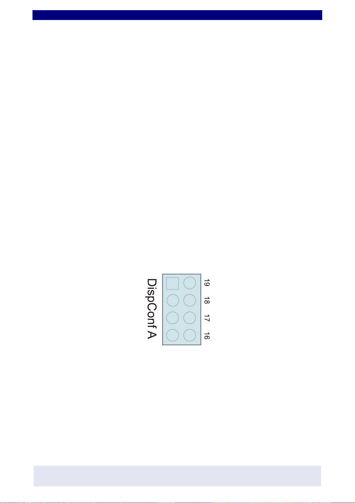
DispConfA
DispConfA is intended to allow configuring of the resolution of the graphics controller to match
an attached TFT-display. Currently it is not in use. Therefore factory default is all jumpers
removed - do not change this setting unless a newer BIOS explicitly allows differing
configuration.
All jumpers removed from DispConfA enables DispConfB (see next page)
Technical Information CV1-AMBIENT • CPCI Graphics Adapter
- 14 -
EKF Elektronik GmbH * Philipp-Reis-Str. 4 * D-59065 HAMM (Germany)
Tel. +49 (0)2381/6890-0 * Fax. +49 (0)2381/6890-90 * E-Mail [email protected] * Internet http://www.ekf.de
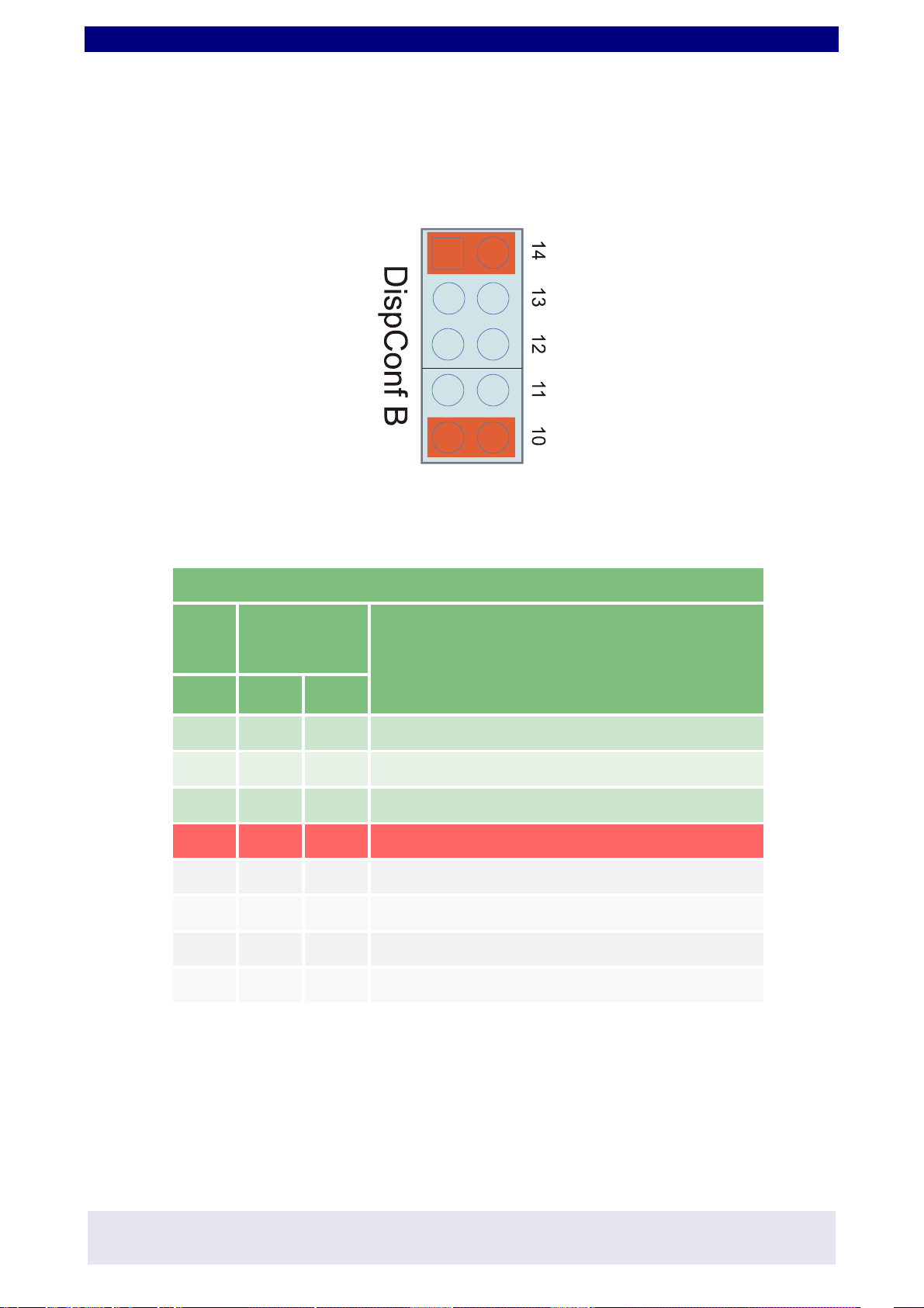
DispConfB
The jumper field DispConfB is provided to match closely the properties of an attached TFT-
display. Please note: DispConfB settings are entirely ignored if any jumper is set to DispConfA.
The factory default setting is described below (positions marked red = jumper set, all others
removed).
DispConfB factory default (requires all jumpers removed from DispConfA)
DispConfB 14:12 O= Jumper Set G=Jumper Removed
Enable
DVI
DVI
Brightness TFT Properties
14 13 12
OOO 9-bit, 3-bit per R, G, B
OOG 12-bit, 4-bit per R, G, B
OGO 18-bit, 6-bit per R, G, B
OGG 24-bit, 8-bit per R, G, B
GOO 24-bit, 12+12-bit, 2 pixels/clock
GOG Analog TFT with analog R, G, B I/F
GGO 36-bit, 18+18-bit, 2 pixels/clock
GGG unused, reserved
DispConfB 14:12 factory default (highlighted red). Use of the DVI interface requires Jumper 14
to be set. Jumpers 12, 13 control the brightness of the DVI port. Jumper 14:12 settings can be
entirely ignored if only the secondary display port (VGA HD-DSUB15 outlet) is in use.

Technical Information CV1-AMBIENT • CPCI Graphics Adapter
- 15 -
EKF Elektronik GmbH * Philipp-Reis-Str. 4 * D-59065 HAMM (Germany)
Tel. +49 (0)2381/6890-0 * Fax. +49 (0)2381/6890-90 * E-Mail [email protected] * Internet http://www.ekf.de
TheJumpers11:10ofDispConfB define thescreen resolutiondeliveredbytheCV1-AMBIENT. Do
not confuse the settings described in the jumper table below with the screen resolution selected
from your operating system.
DispConfB 11:10 O= Jumper Set G=Jumper Removed
11 10 CV1
Selected
Resolution
OS (Windows) Selected Resolution (—Indicates Match)
640 x 480 800 x 600 1024 x 768 1280 x 1024
OO 640 x 480 —panning panning panning
OG 800 x 600 center —panning panning
GO 1024 x 768 center center —panning
GG1280 x 1024 center center center —
DispConfB 11:10 factory default is highlighted red. As could be seen, a perfect match requires
the settings of the CV1-AMBIENT being identical compared to the operating systems selected
resolution.
Jumper EnaI2C
The jumper ENI2C, when set, enables the programming of the PanelLink transmitter by the
System Management Bus (requires I2C controlling software drivers or firmware). As factory
default, this jumper is removed for hard wired configuring of the transmitter. The PanelLink
transmitter is responsible for the encoding and generating of the differential signals of the DVI
interface (Primary Display Port).
Jumper Select Lower
The jumper Select Lower allows to select one of two BIOS memory blocks (A16 EPROM/Flash
Low/High). This assumes sufficient memory capacity (twice as required for normal operation).
The feature could be interesting for developers, who want to select between two BIOS versions,
or need to restore to an older version. As factory default, this jumper is removed.

Technical Information CV1-AMBIENT • CPCI Graphics Adapter
- 16 -
EKF Elektronik GmbH * Philipp-Reis-Str. 4 * D-59065 HAMM (Germany)
Tel. +49 (0)2381/6890-0 * Fax. +49 (0)2381/6890-90 * E-Mail [email protected] * Internet http://www.ekf.de
Primary Display Port - DVI-I Receptacle
Though DVI-I preserves some pins for analog signals, these pins are NC on the CV1-AMBIENT,
resulting in a functionality identical to DVI-D (D = digital). The DVI-I (I = integrated analog and
digital) receptacle however allows use of both, DVI-I and DVI-D cables and accessories at your
convenience.
DVI
17 tx0- 9 tx1- 1 tx2-
18 tx0+ 10 tx1+ 2 tx2+
19 GND 11 GND 3 GND
20 nc 12 nc 4 nc
21 nc 13 nc 5 nc
22 GND 14 ddc_pow 6 ddc_clk
23 txc+ 15 GND 7 ddc_dat
24 txc- 16 dvi_hp 8 nc
c3 nc c1 nc
c6 GND c5 GND
c4 nc c2 nc
TX0..2 = Blue/Green/Red (Single Link) DDC = Display Data Channel DVI-HP = DVI Hot Plug
Please note: The DVI hot plug capability requires initialization of the PanelLink transmitter
accordingly (by I2C).

Technical Information CV1-AMBIENT • CPCI Graphics Adapter
- 17 -
EKF Elektronik GmbH * Philipp-Reis-Str. 4 * D-59065 HAMM (Germany)
Tel. +49 (0)2381/6890-0 * Fax. +49 (0)2381/6890-90 * E-Mail [email protected] * Internet http://www.ekf.de
Secondary Display Port - D-SUB 15-Pos. Connector
1red
2 green
3blue
4nc
5GND
6GND
7GND
8GND
9 +5V (PolySwitch 1.5A) DDC Power
10 GND
11 nc
12 DDC Data
13 Hsync
14 Vsync
15 DDC Clock
Technical Information CV1-AMBIENT • CPCI Graphics Adapter
- 18 -
EKF Elektronik GmbH * Philipp-Reis-Str. 4 * D-59065 HAMM (Germany)
Tel. +49 (0)2381/6890-0 * Fax. +49 (0)2381/6890-90 * E-Mail [email protected] * Internet http://www.ekf.de
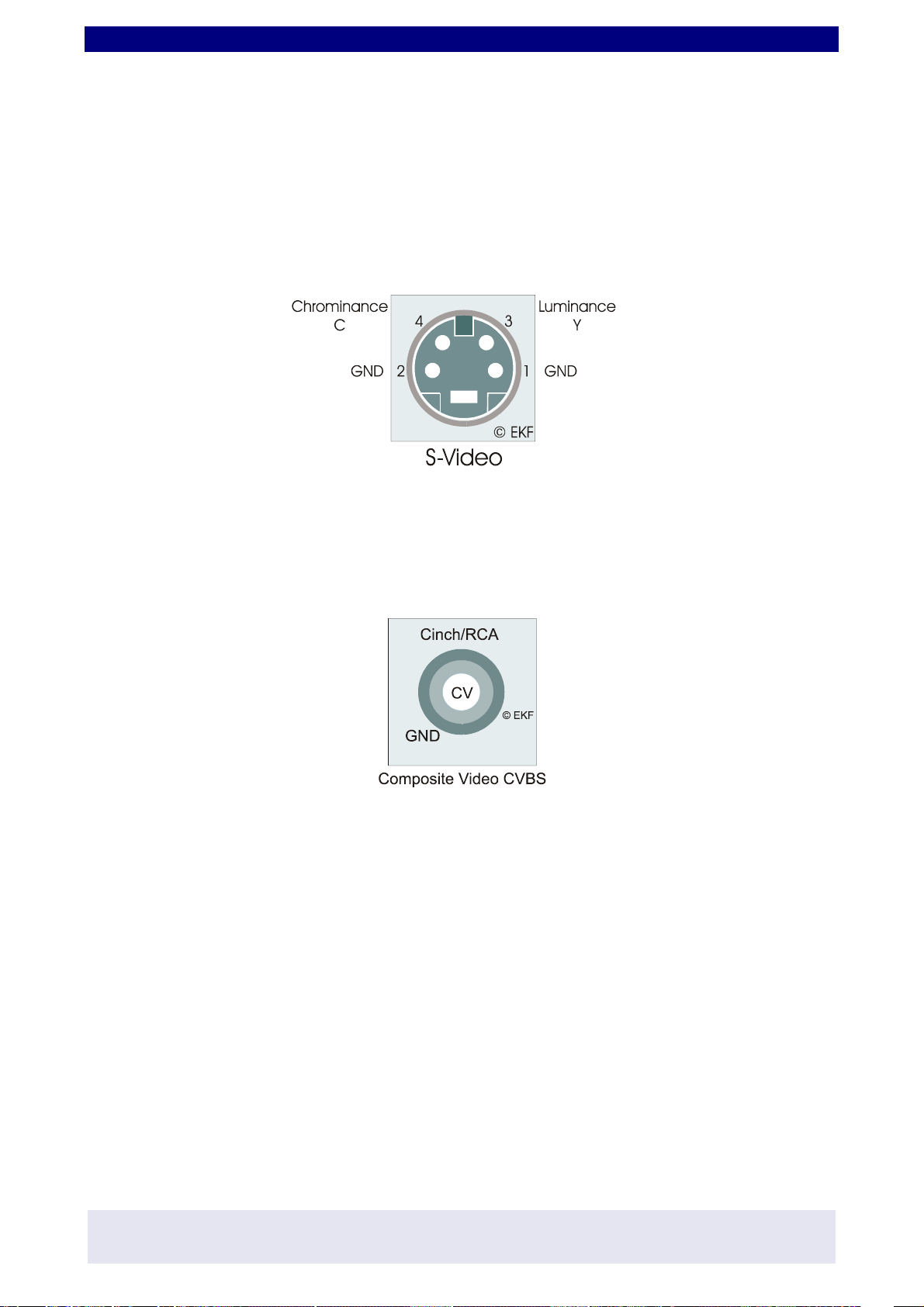
Video Outputs
Due to lack of free space in the cards front panel, the video connectors are mounted in the
middle of the board, thus suitable for internal wiring or open experimental card frames.
Functionally, these outputs are dedicated to the Secondary Display Port.
S-Video Output
Composite Video Output

Technical Information CV1-AMBIENT • CPCI Graphics Adapter
- 19 -
EKF Elektronik GmbH * Philipp-Reis-Str. 4 * D-59065 HAMM (Germany)
Tel. +49 (0)2381/6890-0 * Fax. +49 (0)2381/6890-90 * E-Mail [email protected] * Internet http://www.ekf.de
Zoom Video Port
ZV Y0 1 2 GND
ZV Y1 3 4 GND
ZV Y2 5 6 GND
ZV Y3 7 8 GND
ZV Y4 9 10 GND
ZV Y5 11 12 GND
ZV Y6 13 14 GND
ZV Y7 15 16 GND
ZV UV0 17 18 GND
ZV UV1 19 20 GND
ZV UV2 21 22 GND
ZV UV3 23 24 GND
ZV UV4 25 26 GND
ZV UV5 27 28 GND
ZV UV6 29 30 GND
ZV UV7 31 32 GND
ZV HREF 33 34 GND
ZV VSYNC 35 36 GND
ZV PixCLK 37 38 GND
NC 39 40 NC
I2C Clock 41 42 GND
I2C Data 43 44 GND
Composite Video CVBS 45 46 GND
S-Video Luminance 47 48 GND
S-Video Chrominance 49 50 GND
Y(0..7) Luminance
UV(0..7) Chrominance
HREF Horizontal Sync
VSYNC Vertical Sync
PixCLK Video Clock
Pin Pos. 41...50 are intended for future use together with an add-on module to the CV1-
AMBIENT

Technical Information CV1-AMBIENT • CPCI Graphics Adapter
- 20 -
EKF Elektronik GmbH * Philipp-Reis-Str. 4 * D-59065 HAMM (Germany)
Tel. +49 (0)2381/6890-0 * Fax. +49 (0)2381/6890-90 * E-Mail [email protected] * Internet http://www.ekf.de
BIOS Socket
There are several packaging options for the integrated video BIOS. If contained in a Flash
EEPROM, the BIOS is soldered directly to the board and cannot removed and changed without
appropriate desoldering equipment. Provided as an alternate footprint, a DIP-32 socket allows
for inserting of an EPROM (either 28 or 32-pin Jedec style, e.g. 27C010). When using a 28-pin
EEPROM, the most left positions of the socket must remain free (pin 1 orientation of the socket
and the EPROM is marked by a notch).
This manual does not provide information about the BIOS firmware itself. Latest releases of the
firmware can be downloaded from the EKF website at http://www.ekf.de/c/cgxa/cv1/cv1.html.
You would have to use an ordinary programmer (e.g. Data I/O) in order to program the BIOS
binary image into the EPROM or Flash EEPROM.
Table of contents


