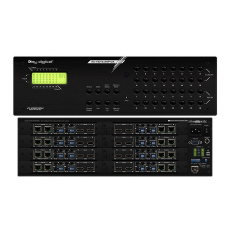
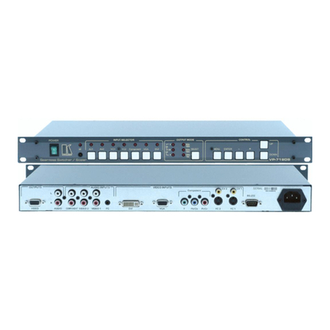
Elabs DVPS44 User manual

DVPS44
Video Wall Processor & Matrix Switch
4x4 HDMI™ Scaler
LAUNAMNOITCURTSNI

THIS PAGE IS LEFT
INTENTIONALLY BLANK

1
SAFETY AND NOTICE
The DVPS44 Video Wall Processor and Matrix Switch 4x4
HDMI™ Scaler has been tested for conformance to safety regula-
tions and requirements, and has been certied for international use.
However, like all electronic equipments, the DVPS44 should be used
with care. Please read and follow the safety instructions to protect
yourself from possible injury and to minimize the risk of damage to
the unit.
• Follow all instructions and warnings marked on this unit.
• Do not attempt to service this unit yourself, except where
explained in this manual.
• Provide proper ventilation and air circulation and do not
use near water.
• Keep objects that might damage the device and assure that the
placement of this unit is on a stable surface.
• Use only the power adapter and power cords and connection
cables designed for this unit.
• Do not use liquid or aerosol cleaners to clean this unit.
• Always unplug the power to the device before cleaning.

2
TABLE OF CONTENTS
INTRODUCTION...................................................................3
FEATURES.............................................................................4
SPECIFICATIONS...................................................................5
PACKAGE CONTENTS...........................................................6
HARDWARE INSTALLATION....................................................7
CONNECTION DIAGRAM.....................................................8
PANEL DESCRIPTIONS..........................................................10
OPERATION BY FRONT PANEL.............................................. 11
OPERATION BY REMOTE CONTROL ......................................... 13
OPERATION BY SOFTWARE CONTROL ......................................... 15
EDID LEARNING..................................………………….. ....... 18
EDID LEARNING FUNCTION......................................................22
WARRANTY..........................................................................23

3
INTRODUCTION
The DVPS44 Video Wall Processor and Matrix Switch 4x4 HDMI Scal-
er provides the most exible and cost eective solution in the market.
The new DVPS44 can be used as a conventional matrix switch, routing
up to four dierent HDMI video sources to any monitor independently
or be used as video wall processor, splitting a chosen image from one
source to four displays.
On top of that, it can work as "combo" gear, showing any individual
input source in full-screen for any selected display while other displays
are working in video wall mode.

4
Features
• HDCP compliant
• Allows any HDMI display to view any HDMI source at any time
• Supports default HDMI EDID and learns the EDID of displays
• Supports HDMI™ DVI input, from 640x480 to 1920x1200@60,
interlaced or progressive
• Four HDMI outputs from 640x480 to 1920x1200
• User-selectable output settings, up to 1920x1200
• Fast response time for channel switch
• Supports 7.1 channel digital audio
• The matrix master can switch every output channels to any HDMI
inputs by push-in button, IR remote control, RS-232 control
• Resize, position, zoom, rotation, fade-in fade-out output video
• CE labs TV Video wall processor calculator for bezel compensation
• Each HDMI output has an independent controllable display area
• Image parameters and layouts are automatically saved in ash
memory of the device and can be recalled for later use
• Several Image parameters and layouts can be saved in software
and can be loaded for later use
• Software control through RS-232
• Firmware upgradable for support of new features and technology
enhancements
• Easy installation with rack-mounting and wall-mounting designs for
master and receiver respectively
• 1U size

5
Technical
Typical usage True 4x4 Matrix, Wall Processor
Video Format Support
Video loop-out
HDCP compliance
Video bandwidth
Video support
Audio support
Input TMDS signal
ESD protection
PCB stack-up
Input
Output
USB connector
Up to 7.1ch Surround Sound of Stereo Digital Audio
HDMI/DVI
Yes
Single-link 225MHz [6.75Gbps]
480i/480p/720p/1080i/1080p60/1920x1200@60Hs 30-bit color
No
1.2 Volts [peak-to-peak]
Human body model — ± 19kV [air-gap discharge]
& ±12kV [contact discharge]
8-layer board [impedance control — dierential 100Ω; single 50Ω]
4x HDMI / 1x RS-232 / 1x Ethernet (for test)/ 1x 2.1mm power jack
4x HDMI/2x USB
Type A
RS-232 connector DE-9 [9-pin D-sub female]
RJ-45 connector WE/SS 8P8C with 2 LED indicators (Not in use)
Mechanical
Enclosure Metal case
Dimensions
[L x W x H]
173/8" x 101/4" x 13/4" [441 x 260 x 44mm]
Fixedness
203/8" x 181/4" x 53/4" [517 x 464 x 146mm]
Power supply
213/4" x 121/2" x 193/4" [570 x 580 x 260mm]
6.4 lbs (102.4 oz) [2.9 Kg]
Model
Package
Carton
9.9 lbs (158.4 oz) [4.5 Kg]
Model
Package
Weight
Operation temperature
Relative humidity
1U rack-mount with ears & wall hanging holes
12V 5A DC 2.1mm, Center pin +
32~104°F [0~40°C]
-4~140°F [-20~60°C]
20~90% RH [no condensation]
Specications
Storage temperature
HDMI connector Type A [19-pin female]
Control Remote Control (IR) / RS-232 / Front Panel Buttons

6
Package Contents
• 1x DVPS44
• 1x Power Adapter DC 12V 5A
• 1x User Manual
• 1x Installation software CD
• 1x IR Remote Control
• 1x Rack-mounting ear set

7
INSTALLATION
1. Connect all HDMI sources to the HDMI Inputs of the DVPS44 Video
Wall Processor and Matrix Switch 4x4 HDMI Scaler
2. Connect all displays (Monitors) to the HDMI Outputs of the DVPS44
3. Connect the RS232 controller cable from the DVPS44 to a PC
4. Connect the +12V 5A DC power supply to the DVPS44
Example Connection Diagram
Used as a Video Wall processor:
You can control the unit by Front panel
or
IR remote control
or
RS232.
Any of the 4 inputs may be selected to create a single image on all 4
monitors.

8
Example Connection Diagram Cont.
Used as Matrix Switch:
You can control the unit by Front panel
or
IR remote control
or
RS232.
Any of the 4 inputs may be routed to any output.
Used as Matrix Switch:
You can control the unit by Front panel
or
IR remote control
or
RS232.
Unit has 4 inputs, displays are showing 2 or 3 of the same input.

9
Example Connection Diagram Cont.
Unit has 4 inputs, all displays are showing same input.

10
PANEL DESCRIPTION
Front Panel
1. Input Status: indicate which Input is connected or activated
2. IR SENSOR: IR receiver commands.
3. Top 7-segment display: show the output display selected to
be setup.
“– Output“ push button: to Select in descending order, the output
Display that will be setup.
“Output +“ push button: to Select in ascending order, the output
Display that will be setup.
4. Bottom 7-segment display: show the input source that will
be displayed.
“– Input“ push button: to Select in descending order the input
source that will be displayed.
“Input +“ push button: to Select in ascending order the input
source that will be displayed.
5. +12V DC: Input power +12V DC 5 Amp. 2.1mm power jack
6. RS-232: RS-232 control port
7. Ethernet: Ethernet control port (Not available for control)
8. INPUT 1–4: HDMI input 1–4 sources
9. USB 5V: Use for power only + 5 Volts output, not control
10. OUTPUT 1–4: HDMI output displays
11. USB 5V: Use for power only + 5 Volts output, not control
Rear Panel
1 2
3
4
8
5 6 7 10
911

11
OPERATION
Front Panel Push-Buttons
1. FRONT PANEL INPUT & OUTPUT SELECTION
1– Use the
“– OUTPUT“
push button: to Select in descending order the
output Display that will be setup. You will be see the selection on
the top 7-segment display.
2– Use the “OUTPUT +“ push button: to Select in ascending order the
output Display that will be setup. You will be see the selection on
the top 7-segment display.
3– Use the “– INPUT“ push button: to Select in descending order the
Input source that will be Displayed. You will be see the selection
on the bottom 7-segment display.
4– Use the “INPUT +“ push button: to Select in ascending order the
Input source that will be Displayed. You will be see the selection
on the bottom 7-segment display.
Once you select the desired Output or Input port, the LED will be
blinking twice and the setting will be eective
2. SAVING YOUR SETUP
1– Push
“OUTPUT+“
(save) button until the output LED shows “d.” to
enter the Save Mode.
2– Use the “INPUT +“ or “– INPUT“ push button to select the mapping
conguration (from 0~7) to which you want to save current input/
output setup mapping.
3– After you select the desired mapping conguration number, the
LED will blink twice and the mapping setting will be saved.
4– If you push the “– OUTPUT“ (preset) button before the mapping
setting is saved, the LED will show “ - ” “ - ” and Mapping will not
be saved.
default
learn
preset
save

12
OPERATION CONT.
3. PRESET MAPPING MODE
1– Push
“– OUTPUT“
(preset) button until the output LED shows “P.” to
enter the Preset Mode.
2– Use the “INPUT+“ or “– INPUT“ push button to select the preview
saved mapping conguration (from 0~7) to which you want to recall.
3– After you select the desired mapping conguration number, the
LED will blink twice and the mapping setting will be in eect.
4– If you push the “OUTPUT+“ (save) button before the mapping
setting is in eect, the LED will show “ - ” “ - ” to quit the Preset
Mapping Mode, the preset setting you select will not be in eect.
4. DEFAULT EDID MODE
1– Keep pushing the
“INPUT +“
(default) button all the process to
select the input channel which you want to learn default EDID.
2– Push the “OUTPUT +“ or “– OUTPUT“ push button, the display will
show “E” “d” one time to enter the Learning Default EDID Mode.
3– Use the “OUTPUT +“ or “– OUTPUT“ push button to select the
default EDID mode (1~8)
4– Release the “INPUT +“ (default) button after selecting the desired
default EDID mode, and then the Display will blink twice and the
setting will be in eect.
5– If you want to quit Learning Default EDID Mode, push the
“– INPUT” (learn) push button before the setting is in eect.
6– The display will show “0” “0” if the setting is success.
The display will show “F” “F” if the setting fails.
5. EDID LEARNING MODE
1– Push
“– INPUT“
(learn) button to select the input channel to which
you want to learn EDID from HDMI output. Then, keep pushing
“– INPUT“
(learn) button when you select your desired input channel.
2– Push the “OUTPUT +“ or “– OUTPUT“ button, and the display will
show "E" "L" one time to enter Learning EDID Mode.
3– Use “– OUTPUT“ push button to select the output port number.
4– Release the “– INPUT“ (learn) button after selecting the desired
output port number, and then the LED will blink twice and the
setting will be in eect.
5– The unit will quit Learning Output EDID Mode, push the “INPUT +”
(default) button before the setting is in eect.
6– The display will show “0” “0” if the setting is success.
The display will show “F” “F” if the setting fails.

13
OPERATION CONT.
IR Remote Control
Input/Output Select
Push the button on the X (input) Y (output)
keyboard to select Input & Output port.
Example:
Select Input 3 to Output 4.
Push the red button as shown
to select Input 3 to Output 4.
Function Key Denition
BUTTONFUNCTION
OFF Standby mode
ON Power on the matrix switcher
MUTE Turn o output’s video and audio
STATUS Preset output status
SAVE Save current mapping mode
PRESET Preset mapping mode
DEFAULT EDID Begin default EDID selection
LEARN EDID Begin EDID learning from one output
CLEAR Clear the previous IR operation procedure
TAKE Trigger the previous setting
F1 All outputs select the same input
F2 Group Setting #1,2,3,4
Examples of Operation
Mute Output:
Ex: Mute Output 2
Mute + A-D (Output 1-4) + Take
1. Press “MUTE” button
2. Press key “B” to select Output 2
3. Press “TAKE” button
PROCEDURE 7-SEGMENT DISPLAY
–
0
2
0
2
0

14
Status + A thru D
(Output 1 thru 4) + Take
1. Press “STATUS” button
2. Press “B” to select Output 2
3. Press “TAKE” button
Save + A thru H
(1 thru 8 storage site) + Take
1. Press “SAVE” button
2. Press “F” to select the storage 6
3. Press “TAKE” button
Preset + A thru H
(1 thru 8 storage site) + Take
1. Press “PRESET” button
2. Press “C” to select the storage 3
3. Press “TAKE” button
Default EDID + A thru H
(1 thru 8 default EDID) + I thru IV
(input 1 thru 4) + Take
1. Press “DEFAULT EDID” button
2. Press “F” to select default EDID 6
3. Press “IV” to select Input 4
4. Press “TAKE” button
Learn + A thru D (Output 1-4) +
I thru IV + Take
1. Press “LEARN” button
2. Press “A” to select Output 1
3. Press “II” to select Input 2
4. Press “TAKE” button
F1 + I thru IV (Input 1-4) + Take
1. Press “F1” button
2. Press “IV” to select Input 4
3. Press “TAKE” button
PROCEDURE 7-SEGMENT DISPLAY
Output Status:
Ex: What Selections
are on Output 2
(If Input 3 is selected)
Save Current Setup
Mapping:
Ex: Save Current
Mapping to 6
Preset Mapping:
Ex: Preset Saved
Mapping from 3
Learned default EDID:
Ex: Default EDID 6
Input 4
Learned Output EDID:
Ex: Learned Output 1
Input 2
F1:
Ex: All Outputs
Select Input 4
–
–
2
–
2
3
d
–
d
6
P
–
P
3
E
d
6
d
6
4
0 (success) F (fail)
0 (success) F (fail)
E
L
1
L
1
2
0 (success) F (fail)
0 (success) F (fail)
A
–
A
4

15
Software Control through RS-232 port
System Requirement
1– OS Information: MS WinXP/7
2– Baud rates: 9600
3– Software size: 3 MB
4– Minimum RAM requirement: 256 MB
Software Bottom Description
1 Display Firmware and software Version 9 EDID Setting
2 Connect/Disconnect RS-232 10 Firmware Update
3 Connect/Disconnect Ethernet 11 Network Setting
4 Select COM Port 12 Mapping Setting
5 Connect/Disconnect Status 13 Default Reset
6 Connect/Disconnect Button 14 In/Out Setting
7 Power On/O Button
8 Advance Setting
Connecting Matrix & Controller (4, 5, 6)
• Use RS-232 cable to connect the RS-232 port on matrix to the PC
– If your PC does not have a RS232 port install the software and hardware for
the USB to RS232 adapter included on the unit.
• Open the CE labs software and Select the correct com port (4)
• Select the connection button (6)
• Verify that the status change from Disconnected to connected status
to to (5)

16
1. Display Firmware and Software Version
• Click Display Firmware and
Software Version button to show
version information
2. Connect/Disconnect RS-232 Button
1– Click Connect/Disconnect RS-232 button to connect to the
RS-232 control port.
2– If RS-232 is connected, the button will show the sign image.
3. Connect/Disconnect Ethernet Button (NOT AVAILABLE)
4. COM Port Selection
• Click button to select COM port
5. Connection Status
• Connected Status:
•Connecting Status:
• Disconnected Status:
6. Connect/Disconnect Button
• Click button to change connection status
7. Power On/Off Button
• Click this button to power ON device
• Click this button to power OFF device (Standby Mode)

17
8. Advanced Setting
• Select the Advanced Setting button
•Select Read Setting From Device then data will show
in left portion of each window output 1-4 (information)
•Go to STEP 1 portion and verify the values. If needed, enter new
values on the Horizontal Start/End and Vertical Start/End then
click Calculate. The calculated result will be displayed in the
INFORMATION portion.
•Go to STEP 2 to split or ne tuning the setup value.
•STEP 3, update the setting to device by selecting Update Setting
to Device
• Output 1 true Output 4: Setting image size for Display output 1 true 4
• Grouping Setting: Setting your TV Wall Display
• TV Wall Calculator: Calculate the display area for each display, you
need to know the Outer and Inner screen size.
• Input Range: Input resolution displaying.
•Selected Area: Setting the output area for the specic output to be
displayed.
•Init X: Start value at X axis for image to be displayed
•Init Y: Start value at Y axis for image to be displayed
•H Start: Adjust the image Higher or lower at Y axis (Horizontal)
from the Start value
•V Start: Adjust the image wide or thin at X axis (Vertical) from
the Start value
•Split: Divide Height value and Vertical value in values of 1 true 10
• Masking: Fine Tune
• Change Output Resolution: Select preset output resolution

18
9. EDID Button
1. Learn EDID from Default
• Select one of the eight preset Default EDID at “From“
• Select the Input (1 thru 4) at “To“
•Select “Learn” button to learn default EDID for that specic input
2. Load EDID File to Input
• Select the Input that you want to load the EDID (1 thru 4) at “To“
• Select “Load” button to load the EDID le to the input
3. Learn EDID from Display
• Select the Output (1 thru 4) at “From“
• Select the Input (1 thru 4) at “To“
• Select “Learn” button to learn the display EDID to the source.
Table of contents
