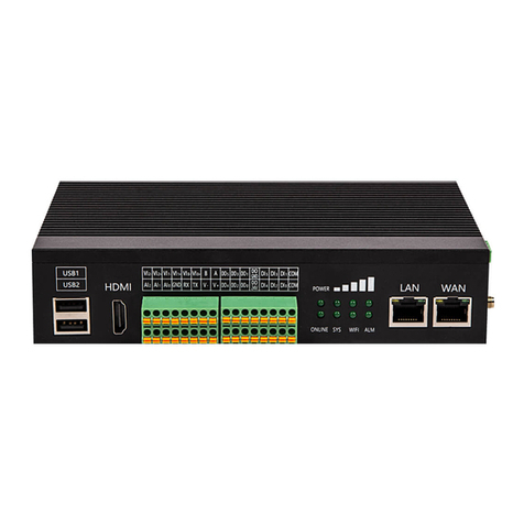
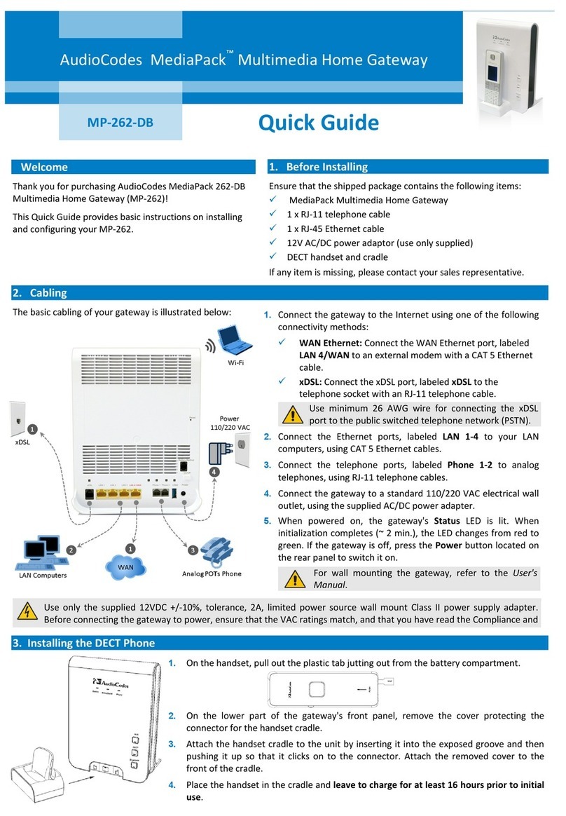
ELASTEL EG500 User manual

Edge Computing Gateway
EG500
User Manual

Industrial Edge Computing Gateway EG500
ELASTEL TECHNOLOGY CO., LTD.
WWW.ELASTEL.COM
Copyright
Copyright © XIAMEN ELASTEL TECHNOLOGIES CO., LTD. All rights reserved.
Trademark
ELASTEL logo is a registered trademark of Xiamen Elastel Technologies Co., Ltd. All other trademarks
belong to their respective vendors or manufactures.
Disclaimer
Product specifications and information in this document are subject to change without any notice,
and ELASTEL reserves the right to improve and change this user guide at any time. Users should take
full responsibility for their application of products, and Xiamen Elastel Technologies Co., Ltd.
disclaims all warranties and liability for the accurateness, completeness of the information
published.
Revision History
Revision
Date
Changes
1.0
2022-03-10
Created
1.1
2022-08-10
Optimized

Industrial Edge Computing Gateway EG500
ELASTEL TECHNOLOGY CO., LTD.
WWW.ELASTEL.COM
Contents
1. Product Introduction....................................................................................................................................5
1.1 Overview.................................................................................................................................................5
1.2 Features..................................................................................................................................................5
1.3 Specifications..........................................................................................................................................5
2. Hardware Introduce .....................................................................................................................................7
2.1 Overview and Dimension........................................................................................................................7
2.2 Interfaces Overview................................................................................................................................8
2.3 Interfaces Definition & Installration.......................................................................................................9
2.3.1 Power supply............................................................................................................................ 9
2.3.2 SIM card and console............................................................................................................... 9
2.3.3 Antenna connectors............................................................................................................... 10
2.3.4 Reset Button .......................................................................................................................... 10
2.3.5 Serial Port (RS232 and RS485) ............................................................................................... 11
2.3.6 DI (Digital Input)..................................................................................................................... 11
2.3.7 DO (Digital Output) ................................................................................................................ 12
2.3.8 AI (Analog input).................................................................................................................... 12
2.3.9 HDMI...................................................................................................................................... 13
2.3.10 Ethernet ............................................................................................................................... 13
2.3.11 USB 2.0................................................................................................................................. 13
2.3.12 LED indicator........................................................................................................................ 14
2.4 Carrier Board Connectors .................................................................................................................... 14
2.4.1 Mini-PCIe 1............................................................................................................................. 15
2.4.2 Mini-PCIe 2............................................................................................................................. 16
2.4.3 WiFi HaLow ............................................................................................................................ 16
2.4.4 Raspberry Pi CM4................................................................................................................... 17
3. ElastOS Operating System Guide............................................................................................................... 18
3.0 Access to WebUI.................................................................................................................................. 18
3.1 Status................................................................................................................................................... 19
3.1.1 Overview................................................................................................................................ 19
3.1.2 Routing................................................................................................................................... 19
3.1.3 Firewall Status........................................................................................................................ 19
3.1.4 System Log ............................................................................................................................. 20
3.1.5 Processes ............................................................................................................................... 20
3.1.6 Realtime Graphs..................................................................................................................... 20
3.1.7 WireGuard.............................................................................................................................. 20
3.2 System ................................................................................................................................................. 21
3.2.1 System.................................................................................................................................... 21

Industrial Edge Computing Gateway EG500
ELASTEL TECHNOLOGY CO., LTD.
WWW.ELASTEL.COM
3.2.2 Administration ....................................................................................................................... 21
3.2.3 Software................................................................................................................................. 22
3.2.4 Startup ................................................................................................................................... 22
3.2.5 Scheduled Tasks ..................................................................................................................... 22
3.2.6 LED Configuration .................................................................................................................. 22
3.2.7 Backup / Flash Firmware........................................................................................................ 23
3.2.8 Reboot.................................................................................................................................... 23
3.3 Services................................................................................................................................................ 24
3.4 Docker.................................................................................................................................................. 24
3.5 Network............................................................................................................................................... 25
3.5.1 Interfaces ............................................................................................................................... 25
3.5.2 Wireless ................................................................................................................................. 27
3.5.3 WiFi HaLow Settings (EG500 WiFi HaLow Version)................................................................ 28
3.5.4 Routing................................................................................................................................... 29
3.5.5 DHCP and DNS ....................................................................................................................... 29
3.5.6 Diagnostics............................................................................................................................. 29
3.5.7 Firewall................................................................................................................................... 29
3.5.8 LoRa Gateway Settings (EG500 LoRaWAN Version)............................................................... 30
3.6 VPN ...................................................................................................................................................... 30
3.7 Data Collect.......................................................................................................................................... 31
3.7.1 Basic Setting........................................................................................................................... 31
3.7.2 Interface Settings................................................................................................................... 32
3.7.3 Modbus Rule Setting.............................................................................................................. 32
3.7.4 S7 Rules Setting...................................................................................................................... 33
3.7.5 IO Setting ............................................................................................................................... 34
3.7.6 Server Setting......................................................................................................................... 36
3.8 Logout.................................................................................................................................................. 36
4. Other Compatible OS Guide ...................................................................................................................... 37
4.1 Installration.......................................................................................................................................... 37
4.1.1 Disassembe the CM4 ............................................................................................................. 37
4.1.2 Install Raspbian OS on CM4................................................................................................... 37
4.1.3 Re-installation CM4................................................................................................................ 38
4.2 Operating Interfaces............................................................................................................................ 38
4.2.1 HDMI GUI............................................................................................................................... 38
4.2.2 Console CLI............................................................................................................................. 39
4.2.3 SSH CLI ................................................................................................................................... 39
4.2.4 WebUI .................................................................................................................................... 39
4.3 Individual Drivers and Programming................................................................................................... 40
Technical Support...................................................................................................................................... 40

Industrial Edge Computing Gateway EG500
ELASTEL TECHNOLOGY CO., LTD.
WWW.ELASTEL.COM
1. Product Introduction
1.1 Overview
The Elastel EG500 is an industrial high-performance Edge Computing Gateway for IoT applications.
Powered by Raspberry Pi CM4, expanded common I/O ports and various networks to support IoT
needs. With rugged, fanless enclosure design. The truly IPC-grade EG500 is used as an IoT gateway,
edge device, or customizable industrial controller… for today’s industrial and embedded applications.
1.2 Features
Powered by Raspberry Pi industrial compute module 4 (CM4), up to 8GB RAM and 32GB eMMC
Built-in dual mini-PCIe sockets for 4G LTE, and LoRaWAN
Reserved SX-NEWAH module for WiFi HaLow (802.11ah) connectivity
Isolated DI/DO/AI/RS232/RS485 interfaces
Embedded watchdog for work stability
Aluminium chassis Fanless cooling design for rugged structural
and wide operating temperature -25~70℃
Fully compatible with Raspbian, OpenWRT, Ubuntu OS, etc.
1.3 Specifications
Hardware platform
CPU
Broadcom BCM2711, Quad-core A72 (ARM v8)@ 1.5 GHz
Memory
2GB (2GB/4GB/8GB optional) LPDDR4
FLASH
8GB (16GB/32GB optional) eMMC
Network & Interfaces
Ethernet
2x Gigabit Ethernet, (1-WAN+1-LAN or 2-LAN Configurable)
Cellular
4G LTE, 3G, 2G, NB-IoT, CAT-M1
Via mPCIe socket
Wi-Fi
Dual Band 2.4GHz & 5GHz + Bluetooth 5.0
LoRaWAN
Supported (Optional, reserved mPCIe for LoRaWAN module)
WiFi HaLow (802.11ah WiFi)
Supported (Optional, reserved SX-NEWAH module for WiFi HaLow)
GPS
Cellular Module built-in supported (Optional)
SIM
1.8 V/3 V; drawer-type Nano card holder × 1
15KV ESD Protection

Industrial Edge Computing Gateway EG500
ELASTEL TECHNOLOGY CO., LTD.
WWW.ELASTEL.COM
Antenna
4G: inside SMA x 1、WiFi/Buletooth: inside SMA x 1, LoRa/WiFi Halow:
inside SMAx1
Industrial Serial Port
RS-232 x 1, RS-485 x 1;
RS-232 signal: TXD, RXD, GND; RS-485 signal: A, B, GND; ESD protection:
15KV
I/O
6-channel digital input DI
(0..24VDC, Configurable Status/Count mode)
3-channel Analog input AI
(0-10V DC, 4-20mA, 18-bit resolution)
6-channel digital/pulse output DO
(0..60V, Max. power 6fficiency: 500 mA)
USB
USB 2.0 x 2 for peripherals,
USB-C x 1 for Console
HDMI
HDMI 2.0 x 1, (Up to 4kp60 video & audio output)
Reset Button
Supported
Power
Power supply
Wide Range Voltages 9~36V DC/1A, recommended 24V/1.5A
Power Terminal
Unpluggable industrial terminal connection
Power consumption
Less than 10 W (system)
Power Output
2-channel power supply for slave devices, same value as Power input (24V)
Mechanical features
Protection
IP30
Housing
Aluminum Heatsink
Cooling
Fanless cooling
Dimensions (cm)
187mm x 112mm x 42mm
Installation
DIN-rail, wall mounting
Weight
790g
Ambient temperature and humidity
Storage temperature
-30 ~ 75°C
Ambient humidity
5 ~ 95% (non-condensing)
Operating temperature
-25 ~ 70°C (industrial grade)
EMC index
Static electricity
level 3
Radiated electric field
level 3
Surge
level 3
Others
LED Indicator
1-POWER, 1-WiFi, 1-SYSTEM, 1-ALARM,1-ONLINE, 3-Signal Strength
Watchdog
Standalone Hardware Watchdog
Warranty
Standard 12 Months
Software Features
OS
Optimized OpenWRT V21 with SDK /Raspbian
Configuration
WebUI, Local CLI, Remote configuration

Industrial Edge Computing Gateway EG500
ELASTEL TECHNOLOGY CO., LTD.
WWW.ELASTEL.COM
Upgrade operate
WebUI, Local USB upgrade and remote upgrade (optional)
Timed startup and shutdown
Supported
Application features
Data Acquisition, Modbus RTU, VPN, Router, Firewall, Media Player…
Python, Node-RED, Docker…,
Support Secondary Development with SDK
Network Features
WWAN and WAN Failover, Load Balance,
PPP, PPPoE, SNMP v1/v2c/v3, TCP, UDP,
DHCP, RIPv1/v2, OSPF, BGP, DNS, DDNS,
Modbus RTU/TCP, Siemens S7, OPC UA, HTTP, MQTT, ARP, QoS, SNTP,
Telnet, SSH
2. Hardware Introduce
2.1 Overview and Dimension

Industrial Edge Computing Gateway EG500
ELASTEL TECHNOLOGY CO., LTD.
WWW.ELASTEL.COM
2.2 Interfaces Overview
Side Panel Interfaces
Front Panel Interfaces

Industrial Edge Computing Gateway EG500
ELASTEL TECHNOLOGY CO., LTD.
WWW.ELASTEL.COM
2.3 Interfaces Definition & Installration
2.3.1 Power supply
EG500 right side panel provide a 4-pin terminal block connector for Power input and a bridge
connection for power output. The defination of PIN 1 “V-“as GND, PIN 2 “V+”for 9V~36V DC
input. While PIN 3 & PIN 4 is a parallel power from PIN 1 & PIN 2, which considering designed
for slave devices power supply.
2.3.2 SIM card and console
There is a secure lock panel on the right side of EG500 to protect the SIM card and Console
port from external unauthorized extraction or tampering. You are allowed to install SIM card
and connect USB-C console port after unlock the cover screws.
Please note Only NANO SIM card size is accepted, and the NANO sim card is inserted with chip
side down.
You may need a PIN insert the hole to pop up the SIM card holder if you need take out the SIM
card.

Industrial Edge Computing Gateway EG500
ELASTEL TECHNOLOGY CO., LTD.
WWW.ELASTEL.COM
2.3.3 Antenna connectors
EG500 provide 3 SMA antenna connectors, two of them are predefined for cellular antenna
and WiFi antenna, while reserved one for other usages, like GPS or second cellular antenna.
Rotate the antenna into the antenna connector accordingly.
The external antenna should be installed vertically always on a site for a good signal.
2.3.4 Reset Button
Reset Button is for reset the EG500 configuration to factory default. To perform reset
operation, you may need a PIN to press and hold the reset button for more than 10 seconds
till the alarm LED indicator flashing, then release. The device will reset all user’s configuration
to factory default and restart.
Serial & DI/DO/AI Ports
EG500 provides two terminal blocks for expanded I/O ports, the ports PIN defination as shown
as the printed label above terminal block accordingly.
They are Serial COM ports as 1xRS485 and 1xRS232, 6 Digital Input ports as DI0 ~DI5, 6 Digital
Output ports as DO0 ~ DO5, 3 Analog Input ports as AI0 ~AI2 (4-20mA current input) or VI0
~VI2 (0-10VDC voltage input).
Also provide a parallel power (V- V+) from power input supply for slave devices.

Industrial Edge Computing Gateway EG500
ELASTEL TECHNOLOGY CO., LTD.
WWW.ELASTEL.COM
2.3.5 Serial Port (RS232 and RS485)
EG500 provide isolated serial COM ports, 1x RS485 and 1xRS232, the PIN B1_15 defined
RS485_A (difference line high), PIN B1_13 defined RS485_B (difference line low).
While the PIN B1_12 defined RS232_Tx (transit line), PIN B1_10 defined RS232_Rx (receive
line), PIN B1_8 defined RS232_GND (reference potential).
A 120 Ohm termination resistor for RS485 has been installed inside.
Check the above application wiring for reference.
2.3.6 DI (Digital Input)
EG500 provide 6x DI to detect the status of outside digital signal, also support count mode to
calculate the frequency.
The DC input voltage is 24V. The 6 digital input are isolated to each other.
Check the above application wiring for reference.

Industrial Edge Computing Gateway EG500
ELASTEL TECHNOLOGY CO., LTD.
WWW.ELASTEL.COM
2.3.7 DO (Digital Output)
EG500 provide 6x DO to control the external slave devices. With an overvoltage protection
circuit that DO 24V wiring, it could filter the overvoltage to avoid destroying device itself.
The external DC power voltage should be under 60V. Check the above application wiring for
reference.
2.3.8 AI (Analog input)
EG500 provide 3x Analog input ports with two types of analog signal, 4-20mA current input,
or 0-10VDC voltage input.
Check the above application wiring for reference.

Industrial Edge Computing Gateway EG500
ELASTEL TECHNOLOGY CO., LTD.
WWW.ELASTEL.COM
2.3.9 HDMI
EG500 uses the CM4’s integrated HDMI to drive the external HDMI Port.
Resolutions up to 4K@ 60Hz are supported.
CEC (Consumer Electronics Control) functionality is also supported, depending on software
configuration
2.3.10 Ethernet
EG500 provide two Gigabit Ethernet ports, the one came out from Raspberry Pi CM4 is pre-
defined as WAN port which supports up to 1Gbps link speeds over standard shielded CAT5e
or CAT6 cables. The connector is the industry standard RJ45 connector.
The second Etherenet port which bridged from Realtek RTL8111 is pre-defined as LAN Port on
EG500, supports up to 1Gbps link speeds over standard shielded CAT5e or CAT6 cables as well.
The connector is the industry standard RJ45 connector.
Two Ethernet ports can be configured as both LAN or other usages freely.
2.3.11 USB 2.0
2x USB 2.0 ports on EG500 front panel are provided for peripheral usage. Together, they may
deliver a maximum of 1A at 5V, depending on peripheral and device configuration.

Industrial Edge Computing Gateway EG500
ELASTEL TECHNOLOGY CO., LTD.
WWW.ELASTEL.COM
2.3.12 LED indicator
EG500 extend 8 LED indicators for apparent status indication as printed label shown,
LED1 is defined as Power indicator which on once power on.
LED2 ~LED4 are defined as cellular signal strength.
LED5 as ONLINE which indicate the network online status.
LED6 for system status.
LED7 for WiFi status.
LED8 for Alarm in case any system error or resetting.
2.4 Carrier Board Connectors
The EG500 carrier board provides some reserved interfaces for user mount necessary modules as
needed, it contains dual mini-PCIe, WiFi HaLow module SX-NEWAH, and Raspberry Pi CM4 socket.

Industrial Edge Computing Gateway EG500
ELASTEL TECHNOLOGY CO., LTD.
WWW.ELASTEL.COM
2.4.1 Mini-PCIe 1
EG500 cellular network is implemented with a mini-PCIe cellular module. To setup EG500 for
cellular functionality, install a cellular module into mini-PCIe socket 1 as drawing red area
add-on module position, only one M2x5 screw is needed.
You can also include cellular network function when place an order from Elastel, Elastel
logistic team will preinstall that from factory.
Elastel supplies EG500 with following cellular module options as default,
4G/LTE CAT4 cellular module, Quectel EC25-E (for EMEA/APAC bands)
4G/LTE CAT4 cellular module, Quectel EC25-AF (for NA bands)
4G/LTE CAT4 cellular module, Quectel EC25-AU (for ANZ/LATAM bands)
Other cellular modules are supported as well, please contact with Elastel representative if
any specific requirements.

Industrial Edge Computing Gateway EG500
ELASTEL TECHNOLOGY CO., LTD.
WWW.ELASTEL.COM
2.4.2 Mini-PCIe 2
EG500 reserved another mini-PCIe socket for LoRaWAN module which develop from
Semtech SX1301, SX1302 solution. Users are allowed to install a LoRaWAN module into mini-
PCIe socket 2 as drawing blue area add-on module position, only one M2x5 screw is needed.
You can also include LoRaWAN network function when place an order from Elastel, Elastel
logistic team will preinstall that for you from factory.
Other mini-PCIe type modules like Zigbee, RF module, WiFi module are supported as well.
Please contact Elastel technical support for further assistance.
2.4.3 WiFi HaLow
EG500 IoT gateway support 802.11ah WiFi (also named WiFi HaLow) network powered by
SX-NEWAH module from SilexTechnology, the first industrial IEEE 802.11ah Wi-Fi module
that operates in the Sub 1GHz band.
Visit SX-NEWAH to learn more benefit of WiFi HaLow technology in IoT.
You can place the EG500 WiFi HaLow version orders from Elastel directly.

Industrial Edge Computing Gateway EG500
ELASTEL TECHNOLOGY CO., LTD.
WWW.ELASTEL.COM
Or you are allowed to mount SX-NEWAH by yourself, the carrier board reserved the interface
for SX-NEWAH module, check the above drawing orange area for module position.
Attention! You may need special weld tool and skill to mount SX-NEWAH on EG500 by
yourself. Incorrect operation may destroy the carrier board and SX-NEWAH.
Purchase EG500 WiFi HaLow version from Elastel directly would be highly recommended.
(https://www.elastel.com/product/industrial-cellular-router/eg500-wifi-halow-gateway/ )
2.4.4 Raspberry Pi CM4
EG500 is built around the Raspberry Pi 4 module (CM4), which provides the following
key features:
Broadcom BCM2711 quad-core Cortex-A72 (ARM v8) 64-bit SoC @ 1.5GHz
1GB, 2GB, 4GB or 8GB LPDDR4 (depending on model)
8GB, 16GB, 32GB eMMC
Optional on-board 2.4GHz and 5.0GHz IEEE 802.11b/g/n/ac WiFi, Bluetooth 5.0, BLE
WiFi / Bluetooth antenna connection is available via RP-SMA connector on the EG500 side
panel, check “2.3.3 Antenna Connectors” section for more details.
The carrier board provide the CM4 corresponding socket on it, you are allowed to mount or
replace different CM4 variants by yourself (Check section 4.1 for more details).
Use caution as the connector is fragile. And be careful the CM4 direction when re-install it,
the position will not match the white area sketch map if CM4 rotated 180 degrees.

Industrial Edge Computing Gateway EG500
ELASTEL TECHNOLOGY CO., LTD.
WWW.ELASTEL.COM
3. ElastOS Operating System Guide
Elastel provide ElastOS operating system which optimized from OpenWRT OS for basic system
management, software management, networks management, I/O (serial ports, DI, AI, DO) ports
communication operations, and other usages. This section guide you how to use ElastOS on EG500.
3.0 Access to WebUI
1) Connect your PC to LAN port of EG500 Gateway directly. Normally your PC will obtain an IP
address 192.168.1.X from EG500 DHCP automatically. If not, please assign a static IP
manually within the same subnet as 192.168.1.1 at 255.255.255.0 mask, while default
gateway as 192.168.1.1
2) Open a web browser on your PC and visit 192.168.1.1 gateway address. The webUI of EG500
should appear and request an username and password to login.
3) Enter the default username and password both “admin” to login the webUI of EG500
Note, you are also allowed to access to EG500 CLI (Command Line Interface for batch scripting) via
SSH or Telnet, once connected your PC to EG500 LAN, rely a putty or Xshell tool to ssh 192.168.1.1
with “admin” for both username and password.

Industrial Edge Computing Gateway EG500
ELASTEL TECHNOLOGY CO., LTD.
WWW.ELASTEL.COM
3.1 Status
3.1.1 Overview
The overview page shows the system information of EG500, it contains system hostname,
model, firmware version, uptime… and so on.
Network section shows the current active network and correspond network type. The
Memory and Storage section shows the status of total available/used space, and others.
3.1.2 Routing
Routing page shows the routing rules are currently active on this system. including IPv4
Routing and IPv6 Routing.
3.1.3 Firewall Status
Firewall status page shows the current filter, NAT, Mangle tables status.

Industrial Edge Computing Gateway EG500
ELASTEL TECHNOLOGY CO., LTD.
WWW.ELASTEL.COM
3.1.4 System Log
The printed system log shows the current behaviors of system, it is useful for
troubleshooting and status moniting.
It provide “Clear log” “Save log” and “Refresh log” operation buttons. You may need click
“Refresh log” to get the real-time log.
3.1.5 Processes
This list gives an overview over currently running system processes and their status.
3.1.6 Realtime Graphs
This page shows the status of Load, Traffic, Wireless status and rate, connections in real time
graphicly.
3.1.7 WireGuard
WireGuard features was enabled as default, this page shows the current status of wireguard
connection.
Other manuals for EG500
1
Table of contents
Other ELASTEL Gateway manuals
