ELBER REBLE610 User manual


REBLE610 Fully indoor Microwave Link
Page 2 of 52 Version 1.4
1Summary
2FIGURE INDEX .................................................................................................................................................... 3
3SAFETY REGULATIONS. ....................................................................................................................................... 7
3.1 TREATMENT OF ELECTRICAL SHOCKS................................................................................................................ 7
3.2 TREATMENT OF ELECTRICAL BURNS.................................................................................................................. 8
4GENERAL DESCRIPTION. ..................................................................................................................................... 9
5TECHNICAL SPECIFICATIONS. .............................................................................................................................. 9
5.1 MODEM DETAILS.................................................................................................................................................. 10
5.2 I/O SIGNALS........................................................................................................................................................ 10
5.3 GENERAL SPECIFICATIONS ...................................................................................................................................... 10
5.4 MECHANICAL SPECIFICATIONS. ............................................................................................................................... 11
6INSTALLATION...................................................................................................................................................11
7USER INTERFACE. ..............................................................................................................................................11
7.1 MAIN MENU. ...................................................................................................................................................... 12
7.2 SUMMARY MENU. ................................................................................................................................................ 12
7.3 MENU UPROCESSOR (UP)...................................................................................................................................... 13
7.3.1 MicroProcessor submenu............................................................................................................................ 13
7.3.2 Menu Setup - System Time.......................................................................................................................... 13
7.3.3 Menu Setup - Touch Screen Calibration. ..................................................................................................... 13
7.3.4 Menu Setup - Reset. .................................................................................................................................... 14
7.3.5 Menu Net - Network parameters................................................................................................................ 14
7.3.6 Menu Misc - General information 1/2. ....................................................................................................... 15
7.3.7 Menu Misc - General information 2/2. ....................................................................................................... 15
7.3.8 Menu Misc - Modules.................................................................................................................................. 16
7.4 MENU MODEM (MODEM UC). .............................................................................................................................. 18
7.4.1 Modem submenu. ....................................................................................................................................... 19
7.4.2 Modem configuration menu. ...................................................................................................................... 19
7.4.3 Modem measurements menu. .................................................................................................................... 19
7.4.4 Modem alarms menu.................................................................................................................................. 21
7.4.5 Modem general menu................................................................................................................................. 23
7.5 MENU I/O (IO)................................................................................................................................................... 24
7.5.1 I/O submenu. .............................................................................................................................................. 24
7.5.2 Ethernet menu. ........................................................................................................................................... 24
7.5.3 ASI/E1 menu................................................................................................................................................ 25
7.5.4 Single connector menu................................................................................................................................ 25
7.6 MENU TRANSMITTER (TX)..................................................................................................................................... 26

REBLE610 Fully indoor Microwave Link
Page 3 of 52 Version 1.4
7.7 MENU RECEIVER (RX)........................................................................................................................................... 26
7.8 MENU POWER SUPPLY (PS)................................................................................................................................... 27
8WEB INTERFACE. ...............................................................................................................................................28
8.1 STATUS. ............................................................................................................................................................. 29
8.1.1 Status-Controller. ........................................................................................................................................ 29
8.1.2 Status-Modem. ........................................................................................................................................... 30
8.2 STATUS-INTERFACE............................................................................................................................................... 31
8.2.1 Status-Transmitter. ..................................................................................................................................... 32
8.2.2 Status-Receiver. .......................................................................................................................................... 33
8.3 TAB CONTROLLER................................................................................................................................................. 33
8.3.1 Controller –Coil fans................................................................................................................................... 34
8.3.2 Controller –Customer. ................................................................................................................................ 34
8.3.3 Controller –Network................................................................................................................................... 35
8.3.4 Controller –Trap Manager. ........................................................................................................................ 36
8.3.5 Controller –Tools. ....................................................................................................................................... 38
8.3.6 Controller –Password management........................................................................................................... 39
8.4 TAB SLOT............................................................................................................................................................ 39
8.4.1 Slot –Modem.............................................................................................................................................. 39
8.4.2 Slot –Interface. ........................................................................................................................................... 43
8.4.3 Slot –TX. ..................................................................................................................................................... 45
8.4.4 Slot –Rx....................................................................................................................................................... 46
8.5 TAB UPGRADE. .................................................................................................................................................... 48
8.6 TAB LOG............................................................................................................................................................. 49
9PANELS..............................................................................................................................................................51
9.1 FRONT PANEL...................................................................................................................................................... 51
9.2 BACK PANEL........................................................................................................................................................ 52
2Figure Index
FIGURE 1: RESUSCITATION DETAIL –1. ........................................................................................................................................ 7
FIGURE 2: RESUSCITATION DETAIL –2. ........................................................................................................................................ 7
FIGURE 3:MAIN MENU FD. .................................................................................................................................................... 12
FIGURE 4:MAIN MENU TX. ..................................................................................................................................................... 12
FIGURE 5:MAIN MENU RX...................................................................................................................................................... 12
FIGURE 6: SUMMARY MENU FD. .............................................................................................................................................. 12
FIGURE 7: MICROPROCESSOR SUBMENU. ................................................................................................................................... 13

REBLE610 Fully indoor Microwave Link
Page 4 of 52 Version 1.4
FIGURE 8: SYSTEM TIME SETTING MENU..................................................................................................................................... 13
FIGURE 9: VIRTUAL KEYPAD. .................................................................................................................................................... 13
FIGURE 10: TOUCH SCREEN CALIBRATION MENU. ........................................................................................................................ 14
FIGURE 11: RESET MENU. ....................................................................................................................................................... 14
FIGURE 12:NETWORK PARAMETERS MENU. ............................................................................................................................... 15
FIGURE 13:GENERAL INFO MENU 1/2....................................................................................................................................... 15
FIGURE 14:GENERAL INFO MENU 2/2....................................................................................................................................... 16
FIGURE 15: GENERAL PURPOSE INFORMATION CONTROLLER. ......................................................................................................... 16
FIGURE 16: GENERAL PURPOSE INFORMATION MODEM................................................................................................................. 17
FIGURE 17: GENERAL PURPOSE I/O INTERFACE INFORMATION. ...................................................................................................... 17
FIGURE 18: GENERAL PURPOSE INFORMATION RX........................................................................................................................ 18
FIGURE 19: GENERAL PURPOSE INFORMATION TX........................................................................................................................ 18
FIGURE 20: MODEM SUBMENU................................................................................................................................................ 19
FIGURE 21:MODEM FD CONFIGURATION MENU......................................................................................................................... 19
FIGURE 22:MODEM FD MEASUREMENT MENU. ......................................................................................................................... 20
FIGURE 23:MODEM TX MEASUREMENT MENU. .......................................................................................................................... 20
FIGURE 24:MODEM RX MEASUREMENT MENU........................................................................................................................... 20
FIGURE 25:MODEM FD MEASUREMENTS MENU (2).................................................................................................................... 20
FIGURE 26:MODEM TX MEASUREMENTS MENU (2). ................................................................................................................... 20
FIGURE 27:MODEM RX MEASUREMENTS MENU (2). ................................................................................................................... 20
FIGURE 28: MODEM XPIC MEASUREMENTS MENU FD................................................................................................................. 21
FIGURE 29:MODEM XPIC MEASUREMENTS MENU TX.................................................................................................................. 21
FIGURE 30: MODEM XPIC MEASUREMENTS MENU RX. ................................................................................................................ 21
FIGURE 31:MODEM ALARMS MENU FD. ................................................................................................................................... 21
FIGURE 32:MODEM ALARMS MENU TX..................................................................................................................................... 21
FIGURE 33:MODEM ALARMS MENU RX..................................................................................................................................... 21
FIGURE 34:MODEM GENERAL MENU FD. .................................................................................................................................. 23
FIGURE 35:MODEM GENERAL MENU TX.................................................................................................................................... 23
FIGURE 36:MODEM GENERAL MENU RX.................................................................................................................................... 23
FIGURE 37: I/O SUB-MENU..................................................................................................................................................... 24
FIGURE 38: MENU ETHERNET.................................................................................................................................................. 24
FIGURE 39: GENERAL ASI/E1 MENU......................................................................................................................................... 25
FIGURE 40: BNC CONNECTOR CONFIGURATION AND STATUS MENU. ............................................................................................... 25
FIGURE 41:TRANSMITTER MENU.............................................................................................................................................. 26
FIGURE 42:RECEIVER MENU.................................................................................................................................................... 27
FIGURE 43: POWER SUPPLY MENU............................................................................................................................................ 27
FIGURE 44: ICON POWER SUPPLY WITH CONTINUOUS CURRENT,PRIMARY POSITION. .......................................................................... 27
FIGURE 45: ICON POWER SUPPLY WITH CONTINUOUS CURRENT,SECONDARY POSITION. ...................................................................... 27
FIGURE 46: ICON POWER SUPPLY WITH ALTERNATING CURRENT,PRIMARY POSITION........................................................................... 28

REBLE610 Fully indoor Microwave Link
Page 5 of 52 Version 1.4
FIGURE 47: ICON POWER SUPPLY WITH ALT ALTERNATING CURRENT,SECONDARY POSITION.................................................................. 28
FIGURE 48: WEB INTERFACE LOGIN PAGE. .................................................................................................................................. 28
FIGURE 49: WEB STATUS FORM –CONTROLLER........................................................................................................................... 29
FIGURE 50: WEB STATUS FORM –CONTROLLER FANS................................................................................................................... 30
FIGURE 51: WEB STATUS FORM –MODEM LOCKED...................................................................................................................... 30
FIGURE 52: WEB STATUS FORM –MODEM UNLOCKED.................................................................................................................. 30
FIGURE 53: WEB STATUS FORM –INTERFACE ASI/E1.................................................................................................................. 31
FIGURE 54: WEB STATUS FORM –INTERFACE LOOP. .................................................................................................................... 32
FIGURE 55: WEB STATUS FORM –TX. ....................................................................................................................................... 32
FIGURE 56: WEB STATUS FORM –RX........................................................................................................................................ 33
FIGURE 57: WEB CONTROLLER FORM –FANS.............................................................................................................................. 34
FIGURE 58: WEB CONTROLLER FORM –CUSTOMER INFO.............................................................................................................. 34
FIGURE 59:WEB CONTROLLER FORM –NETWORK PARAMETERS.................................................................................................... 35
FIGURE 60: WEB CONTROLLER FORM –MODEM SNMP TRAPS CONFIGURATION. ............................................................................. 36
FIGURE 61: WEB CONTROLLER FORM –DATA INTERFACE SNMP TRAPS CONFIGURATION................................................................... 36
FIGURE 62: WEB CONTROLLER FORM –BASEBAND SIGNALS SNMP TRAPS CONFIGURATION................................................................ 36
FIGURE 63: WEB CONTROLLER FORM –RECEIVER SNMP TRAPS CONFIGURATION............................................................................. 36
FIGURE 64: WEB CONTROLLER FORM –TRANSMITTER SNMP TRAPS CONFIGURATION. ...................................................................... 37
FIGURE 65: WEB CONTROLLER FORM –CONTROLLER SNMP TRAPS CONFIGURATION. ....................................................................... 37
FIGURE 66: WEB CONTROLLER FORM -ALARM RELAY CONFIGURATION............................................................................................ 37
FIGURE 67: WEB CONTROLLER FORM –TRAP DESTINATION CONFIGURATION. .................................................................................. 37
FIGURE 68: WEB CONTROLLER FORM –GENERAL INFO AND TOOLS. ................................................................................................ 38
FIGURE 69: WEB CONTROLLER FORM –PASSWORD MANAGEMENT. ................................................................................................ 39
FIGURE 70: WEB SLOT MODEM FORM –STATUS.......................................................................................................................... 40
FIGURE 71: WEB SLOT MODEM FORM –MSE GRAPHIC................................................................................................................ 40
FIGURE 72: WEB SLOT MODEM FORM –TEMPERATURE MANAGEMENT. .......................................................................................... 41
FIGURE 73: WEB SLOT MODEM FORM –PROFILE MANAGEMENT. ................................................................................................... 41
FIGURE 74: WEB SLOT MODEM FORM –PROFILE MANAGEMENT EXPANDED. .................................................................................... 41
FIGURE 75: WEB SLOT MODEM FORM –OPERATIONAL MODE MANAGEMENT.................................................................................. 42
FIGURE 76: WEB SLOT MODEM FORM –OPERATIONAL MODE MANAGEMENT EXPANDED................................................................... 42
FIGURE 77: WEB SLOT INTERFACE FORM –STATUS. ..................................................................................................................... 43
FIGURE 78: WEB SLOT INTERFACE FORM –INPUT/OUTPUT PORTS MANAGEMENT.............................................................................. 43
FIGURE 79: WEB SLOT INTERFACE FORM –INTERNAL LOOP MANAGEMENT........................................................................................ 44
FIGURE 80: WEB SLOT INTERFACE FORM –ETHERNET PORT MANAGEMENT. ..................................................................................... 44
FIGURE 81: WEB SLOT INTERFACE FORM –ETHERNET PORT MANAGEMENT. ..................................................................................... 44
FIGURE 82: WEB SLOT TX FORM –STATUS................................................................................................................................. 45
FIGURE 83: WEB SLOT TX FORM –TEMPERATURE MANAGEMENT. ................................................................................................. 45
FIGURE 84: WEB SLOT TX FORM –POWER MANAGEMENT............................................................................................................ 46
FIGURE 85: WEB SLOT TX FORM –FREQUENCY........................................................................................................................... 46

REBLE610 Fully indoor Microwave Link
Page 6 of 52 Version 1.4
FIGURE 86: WEB SLOT RX FORM –STATUS. ................................................................................................................................ 46
FIGURE 87: WEB SLOT RX FORM –RSSI GRAPHIC. ...................................................................................................................... 47
FIGURE 88:WEB SLOT RX FORM –FREQUENCY........................................................................................................................... 47
FIGURE 89: WEB SLOT RX FORM –TEMPERATURE MANAGEMENT................................................................................................... 47
FIGURE 90: WEB UPGRADE FORM –CONFIGURATION FILE UPLOADER. ........................................................................................... 48
FIGURE 91: WEB UPGRADE FORM –MACHINE UPGRADE. ............................................................................................................ 48
FIGURE 92 :WEB LOG FORM –AVAILABLE LOG. .......................................................................................................................... 49
FIGURE 93: WEB LOG FORM –AVAILABLE LOG EXPANDED. ............................................................................................................ 49
FIGURE 94: WEB LOG FORM –LOG........................................................................................................................................... 50
FIGURE 95: WEB LOG FORM –FILTERS. ..................................................................................................................................... 50
FIGURE 96: WEB LOG FORM –FILTERS (SELECTION OF NUMBER OF LINES PER PAGE)........................................................................... 51
FIGURE 97 :REBLE610 FRONT PANEL. ..................................................................................................................................... 51
FIGURE 98: REBLE610 BACK PANEL......................................................................................................................................... 52
REBLE610 Fully indoor Microwave Link
Page 7 of 52 Version 1.4
3Safety regulations.
The personnel engaged with the installation, the use and the maintenance of the equipment has to be
familiar with the theory and practice of first aid.
3.1 Treatment of electrical shocks.
When the victim loses his consciousness:
Put into practice the following first aid principles.
Position the victim lying down on his back on a rigid surface.
Open the respiratory airways lifting up the neck and pushing down the front (Fig. 1).
If necessary, open the mouth to check the respiration.
In case the victim doesn’t breath, start immediately the artificial respiration (figure 2): bend the
head, close the nostrils, attach the mouth to the victim one’s and do 4 quick mouth-to-mouth
respirations
Figure 1: Resuscitation detail –1.
Figure 2: Resuscitation detail –2.
Check the pulsation (Figure 3); in case of absence of pulsation, start immediately the cardiac
massage (Figure 4) pressing the breastbone in the middle of the thorax (Figure 5).
Figura 1: Resuscitation detail –3.
Figura 2: Resuscitation detail –4.
Figura 3: Resuscitation detail –5.
When there is only one rescuer, he has to maintain a rhythm of 15 compressions alternated with 2
quick respirations.
In case there are two rescuers, the rhythm should be one respiration each 5 compressions.
Do not interrupt the cardiac massage during the artificial breathing
Call a doctor as soon as possible
When the victim is conscious
Cover up the victim with a blanket.
Try to calm down the victim.
Unbutton the cloche and lay down the victim.

REBLE610 Fully indoor Microwave Link
Page 8 of 52 Version 1.4
Call a doctor as soon as possible.
3.2 Treatment of electrical burns.
Large burns and cuts of the skin
Cover up the interested area with a clean sheet or cloth.
Do not open the blisters; remove the fabric and the parts of the clothes attached to the skin; apply
a suitable ointment.
Treat the victim according to the type of accident.
Take the victim to the hospital as soon as possible.
When the arms and legs are affected keep them raised.
When there is no doctor available within an hour and the victim is conscious and does not retch, give a
liquid solution containing salt and sodium bicarbonate: 1 teaspoon of salt and half a teaspoon of sodium
bicarbonate for each 250 ml of water.
Have the victim sip half a glass of the solution for four times and for 15 minutes.
Stop when retching.
Do not give any alcoholics
Less serious burns
Apply cold (not frozen) gauzes using a clean as possible cloth.
Do not open the blisters; remove the fabric and the parts of the clothes attached to the skin; apply
a suitable ointment.
When necessary, put on clean and dry clothes.
Treat the victim according to the type of accident.
Take the victim to the hospital as soon as possible.
When the arms and legs are affected keep them raised.

REBLE610 Fully indoor Microwave Link
Page 9 of 52 Version 1.4
4General Description.
The REBLE610 is a very flexible microwave link that offers heterogeneous signals transport adapting
transmitting capacity to data stream.
It is the evolution of the already innovative and performing REBLE310, from which is distinguished by an
accurate hardware design, with particular care in the modularity and in avoiding any internal cabling.
The equipment is composed by a basic chassis and four swappable parts that make easy the maintenance
process and the always critical frequency change; a dual redundant power supply, hot swappable, is
present, available both in AC and DC version. A slot with the digital part (modem and data interface) has
been realized, as well as a module hosting the whole RF part (transmitter, receiver and channel filters).
The transmitters (at different frequencies) have been improved, being able to give always at least 1W at
output flange in any modulation scheme, introducing pre-correction and wideband calibration (up to 1 GHz,
depending on the frequency).
Data interface is equipped with 10 ASI/BTS ports on BNC connectors, configurable as input or output; this
feature let have in a single chassis the functions of an ASI matrix and an ASI distributor, both in input and
output. The link let also transfer IP traffic on a GbE port, an E1 2.048 Kbps signal and a “transit” connection
(just not to use too many coaxial cables for the transit).
With the optional XPIC module (and another REBLE610), it is possible to double the capacity of the link,
transmitting both in polarization H and V, erasing the undesired signal with special algorithms.
The compactness (1U rack 19”) is one of the main features, together with the care in the details for an easy
installation and maintenance, and the outstanding performances in terms of power, sensitivity and notch
tolerance.
The equipment can be half duplex (transmitter or receiver) or full-duplex.
5Technical Specifications.
Table 1
2-4.2
4.4-5.0
5.0-5.5
5.8-7.1*
7.1-7.7
7.7-8.5
10.0-10.7*
10.7-11.7
12.7-13.2
14.0-15.5
Power [QPSK] after circulator
[dBm] (*dielectric resonator
filters)[1 dB less for standard
filters]
35
34
30
Power out [256 QAMafter
circulator [dBm](*dielectric
resonator filters)
30
29
26
RF connectors/flanges
N
N or
UER70
N
UBR120
UBR140
Table 2
Configuration
Full-duplex or Half-duplex
Conversion
Direct
RF Output Return Loss
> 23 dB
RF Input Return Loss
> 23 dB
Spurious suppression
> 65 dBc

REBLE610 Fully indoor Microwave Link
Page 10 of 52 Version 1.4
Frequency stability
± 1 ppm
Standard channels
1.75/3.5/7/14/20/28/29,65/30/40/56 MHz
Modulation scheme
QPSK; 8PSK
16-32 APSK
16-32-64-128-256QAM
Capacity*
Up to 310 Mbit/s
Table 3: Performances examples in a 28 MHz channel.
Modulation
Sensitivity
Payload
QPSK
-88 dBm
36.665 Mbit/s
8PSK
-82 dBm
54.998 Mbit/s
16QAM
-81 dBm
73.331 Mbit/s
32QAM
-78 dBm
91.664 Mbit/s
64QAM
-74 dBm
123.384 Mbit/s
128QAM
-71 dBm
148.409 Mbit/s
256QAM
-68 dBm
173.726 Mbit/s
5.1 Modem details.
All modem parameters are tied to configuration released by Elber s.r.l.; parameters cannot be manually
modified.
Table 4
Modulation schemes
QPSK; 8PSK
16-32 APSK
16-32-64-128-256QAM
Protection codes *
1. Low Density Parity Check (LDPC) encoder
2. Reed-Solomon with K from 6 to 255 and t
from 0 to 16 and Convolutional Trellis or
Block codes (1/2-13/14).
Programmable internal interleaver
Max Symbol rate
49.5 MBaud
Bandwidth*
1.75 ÷ 56 MHz
Roll-off shaping filter *
0.15 ÷ 0.30
5.2 I/O signals.
Table 5
Access
10xASI/BTS
1xE1
1xGbE
ASI/BTS, E1 Connectors
BNC 75 Ohm unbalanced
Connector GbE, 1+1, XPIC, Transit
RJ-45
5.3 General Specifications
Table 6
Operative Temperature
Range
-10°C ÷ 55°C
Management
Front panel (Display TFT touchscreen)
SNMP
Web browser
Firmware upgrade
USB, WEB, FTP
Power supply
Two, hot swappable.
AC 90-260 V~ 50/60 Hz IEC 320
DC 22 ÷ 65 V 2 pins socket

REBLE610 Fully indoor Microwave Link
Page 11 of 52 Version 1.4
Max power consumption
100 W
Max dissipation
110 W
5.4 Mechanical Specifications.
Table 7
Rack
Standard 19” 1U
Width
482.6 mm
Height
43.6 mm
Depth
554.85 mm (with circulator and hangings)
512.85 mm without circulator
Max Weight
8 Kg
6Installation.
Unpack the equipment and check first of all check if there are any damages due to the transport.
The box should contain:
oThe REBLE610
o1 or two AC supply cable (depending on number and type of power supplies purchased)
o1 or two DC supply cable, equipment adapted connector on one side, free wires at other
end (depending on number and type of power supplies purchased)
oThe user manual
Install the equipment in a rack cabinet. A one-unit space is requested. Verify that there is enough
space between other functioning equipment generating high temperatures and that there are no
obstructions in the ventilation. (The functioning is guaranteed in a temperature range from -10 ºC ÷
+55 ºC).
The equipment must be correctly grounded, to guarantee a secure functioning.
Connect to the correct power tension reading the information on the manual or on the label
attached to each equipment, containing the serial number.
Connect the network cable to the plug on the rear of the equipment or connect the battery cable to
the related connector. The last used configuration will be loaded.
Connect the flange(s) on the rear panel (or N connectors, depending on frequencies) of the
equipment to the waveguide/cable for the connection to the branching system and the antenna.
Setup the equipment according to the needs consulting the user manual.
7User interface.
The user interface consists of a general alarm led and a graphical TFT display with TOUCH SCREEN function
(for more comfortable use, a stick is available in a compartment located in the front panel , see 9.1).
According to equipment configuration (Half-duplex transmitter[Tx], Half-duplex receiver [Rx], Full-
duplex[FD]), just the related menu are shown.
In order to have a read/write privilege and thus modify the configuration of the equipment, it’s required
the connection of a USB pen with the right token to the USB port in the front panel; on the other end, it’s
required to digit a numeric password while trying to modify one parameter (the password is tied to the
customer’s name and it’s notified at delivery).

REBLE610 Fully indoor Microwave Link
Page 12 of 52 Version 1.4
7.1 Main menu.
At equipment switch on, after embedded software boot, display shows the main menu, according to the
configuration, as can be seen in Figure 3, Figure 4 and Figure 5.
This menu shows the equipment block diagram, for an easy and intuitive access to modules parameters
according to their function; on every active area, one or more circles symbolizing alarm led are shown,
eventually red or green depending on the status of the related block.
Figure 3: Main menu FD.
Figure 4: Main menu Tx.
Figure 5: Main menu Rx.
Active areas:
Rx
Tx
Modem uC
I/O
uP
PS
Bus
7.2 Summary menu.
Summary menu reports the most important information for a fast check of the equipment functioning;
indeed following measurements and indications are shown:
Equipment Power out (FD and Tx)
RSSI Received Signal Strength Indication (FD and Rx)
MSE Mean Square Error (FD and Rx)
Modulator locking status Timing Loop (FD and Tx)
Demodulator locking status Dem Lock (FD and Rx)
Figure 6: Summary menu FD.
Active areas:
Directional arrow “UP” to go back to main menu.
REBLE610 Fully indoor Microwave Link
Page 13 of 52 Version 1.4
7.3 Menu uProcessor (uP).
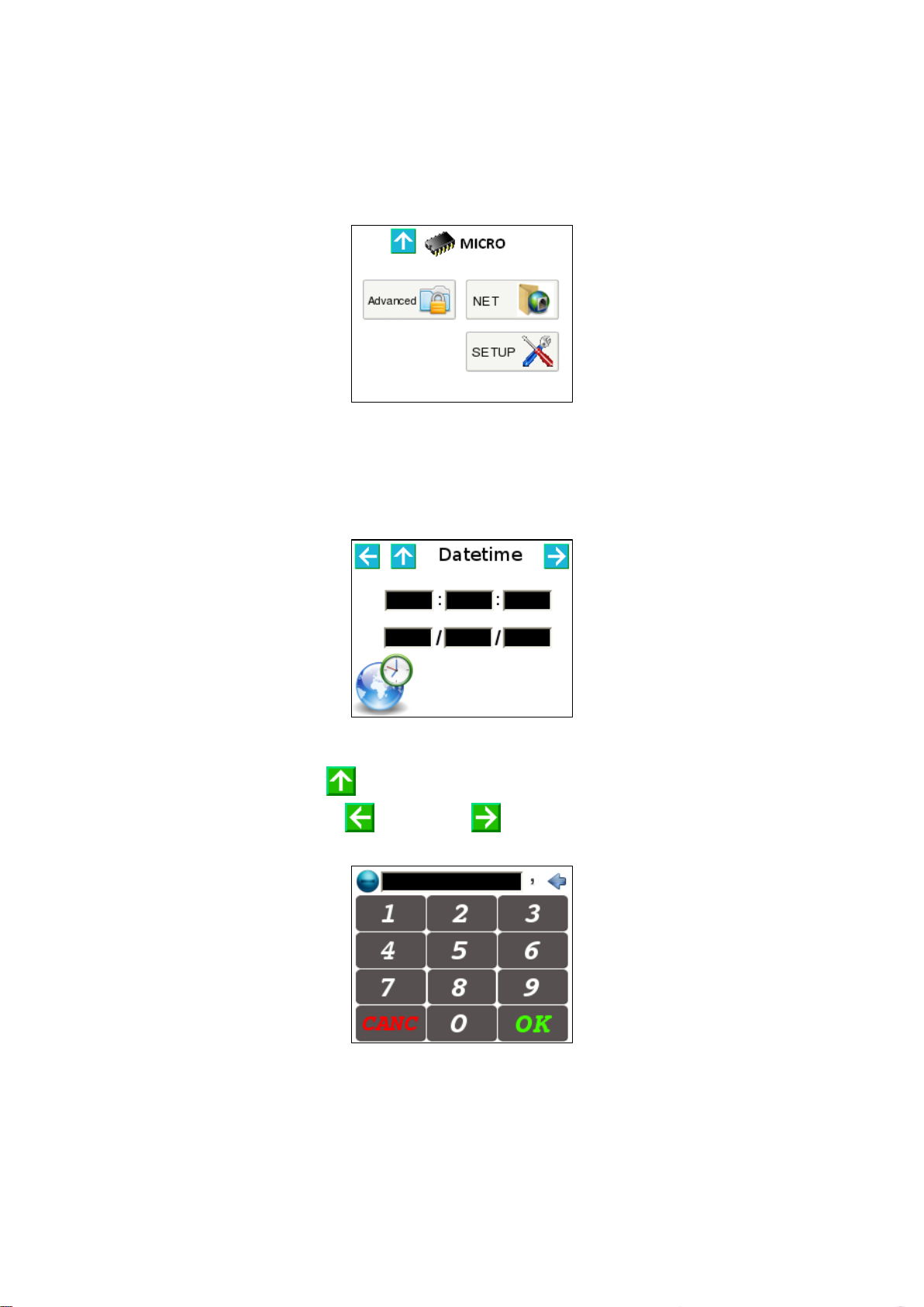
7.3.1 MicroProcessor submenu.
The submenu let a fast access to the elements to be controlled; icons meaning, concerning different
sections, is intuitive.
Figure 7: Microprocessor submenu.
7.3.2 Menu Setup - System Time.
This menu let the user set right time and date, used by the system for alarm logging. Information about
system time is preserved by the battery of the Real Time Clock.
Figure 8: System time setting menu.
Active areas:
Directional arrow “UP” to go back to main menu.
Directional arrows “LEFT” and “RIGHT” to browse microprocessor menu.
Every text box which opens a virtual keypad to enter information.
Figure 9: Virtual keypad.
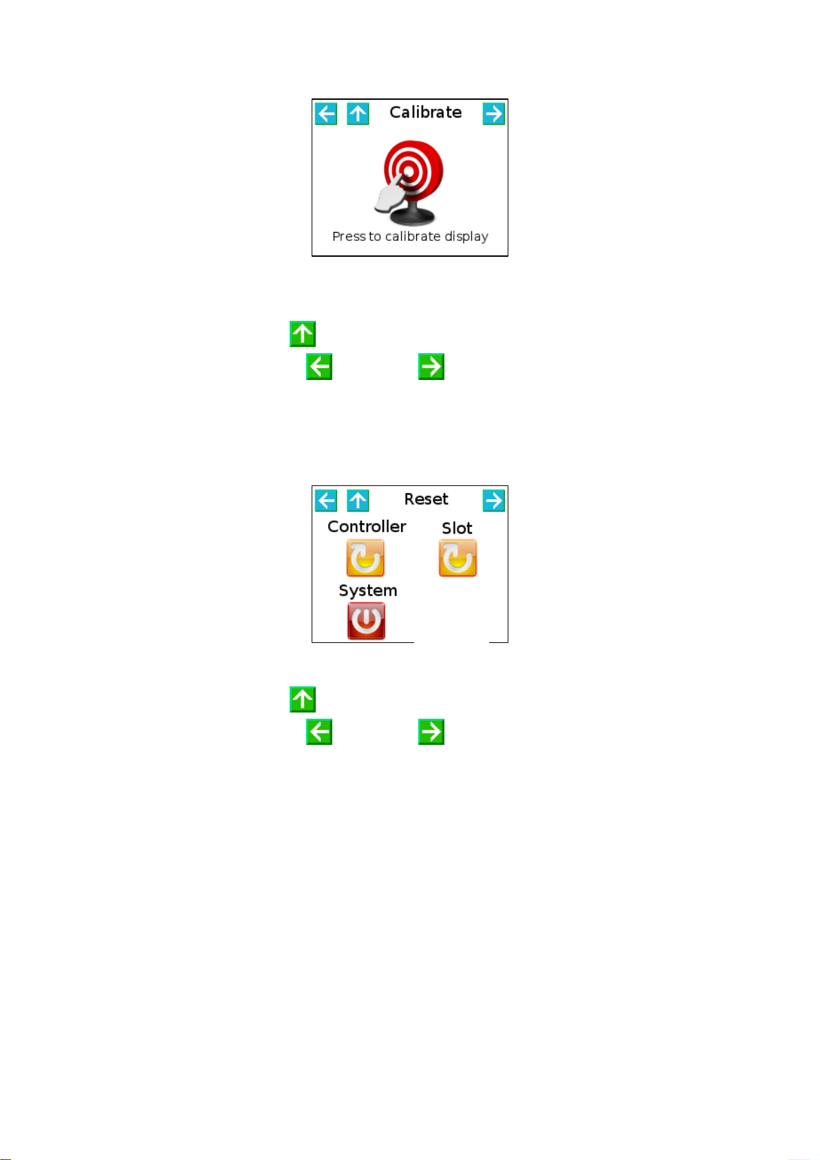
7.3.3 Menu Setup - Touch Screen Calibration.
This menu let the user calibrate the Touch Screen function. It’s recommended to use the stick provided
with the equipment to touch the red cross, three time as required by the system, after Calibrate button
pushing.
REBLE610 Fully indoor Microwave Link
Page 14 of 52 Version 1.4
Figure 10: Touch Screen Calibration menu.
Active areas:
Directional arrow “UP” to go back to main menu.
Directional arrows “LEFT” and “RIGHT” to browse microprocessor menu.
7.3.4 Menu Setup - Reset.
This menu let the user reset each microcontroller and FPGA of the equipment.
Figure 11: Reset menu.
Active areas:
Directional arrow “UP” to go back to main menu.
Directional arrows “LEFT” and “RIGHT” to browse microprocessor menu.
Reset icons.
SLOT reset will eventually restart modem and data interface; CONTROLLER reset just reboot system
supervisor, SYSTEM reset is the complete reset of the equipment.
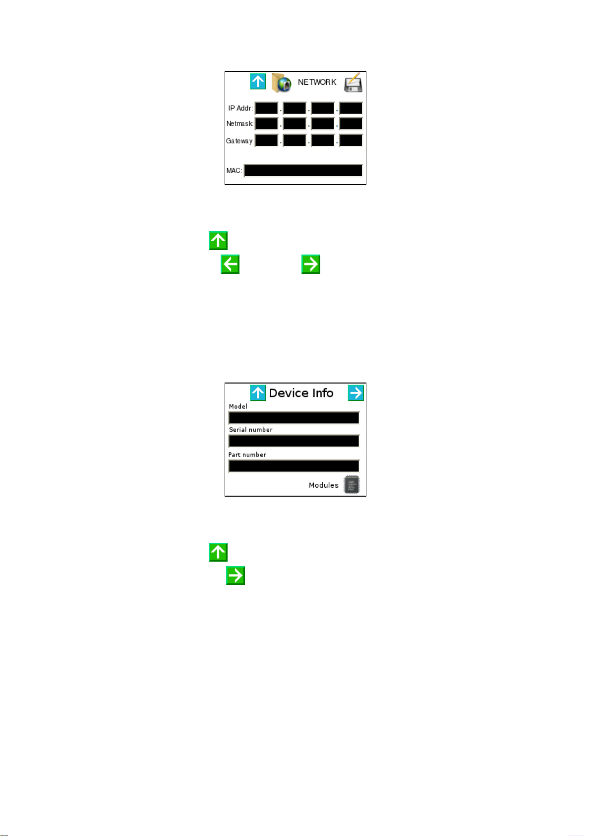
7.3.5 Menu Net - Network parameters.
This menu let the user modify management port network parameters; in detail, it is possible to set IP
address, Subnet Mask and Gateway IP. MAC Address is read-only.
REBLE610 Fully indoor Microwave Link
Page 15 of 52 Version 1.4
Figure 12: Network parameters menu.
Active areas:
Directional arrow “UP” to go back to main menu.
Directional arrows “LEFT” and “RIGHT” to browse microprocessor menu.
Every text box, which opens the virtual keypad to insert characters.
7.3.6 Menu Misc - General information 1/2.
This menu shows general purpose information, such as:
Model
Serial Number
Part Number
Figure 13: General info menu 1/2.
Active areas:
Directional arrow “UP” to go back to main menu.
Directional arrow “RIGHT” to browse microprocessor menu.
Modules icon.
7.3.7 Menu Misc - General information 2/2.
This menu shows general purpose information, such as:
Customer name (two rows)
Installation site (Loc.)
Site from which it receives and site to which is transmitting (eventually filtered in half-duplex
configuration).

REBLE610 Fully indoor Microwave Link
Page 16 of 52 Version 1.4
Figure 14: General info menu 2/2.
Active areas:
Directional arrow “UP” to go back to main menu.
Directional arrows “LEFT” and “RIGHT” to browse microprocessor menu.
7.3.8 Menu Misc - Modules.
7.3.8.1 Menu Misc - Modules - Controller.
This menu shows controller general purpose information such as:
Model
Version
Revision
Figure 15: General purpose information controller.
Active areas:
Directional arrow “UP” to go back to main menu.
Directional arrows “LEFT” and “RIGHT” to browse microprocessor menu.
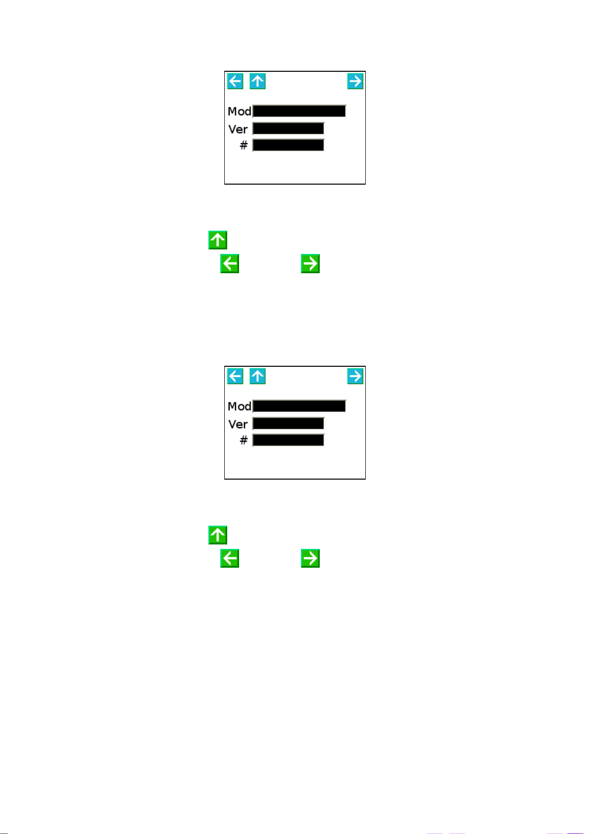
7.3.8.2 Menu Misc - Modules - Modem.
This menu shows modem general purpose information such as:
Model
Version
Revision

REBLE610 Fully indoor Microwave Link
Page 17 of 52 Version 1.4
Figure 16: General purpose information modem.
Active areas:
Directional arrow “UP” to go back to main menu.
Directional arrows “LEFT” and “RIGHT” to browse microprocessor menu.
7.3.8.3 Menu Misc - Modules - Interfaces.
This menu shows I/O interface general purpose information such as:
Model
Version
Revision
Figure 17: General purpose I/O interface information.
Active areas:
Directional arrow “UP” to go back to main menu.
Directional arrows “LEFT” and “RIGHT” to browse microprocessor menu.
7.3.8.4 Menu Misc - Modules - Rx.
This menu shows receiver general purpose information such as:
Model
Version
Revision
REBLE610 Fully indoor Microwave Link
Page 18 of 52 Version 1.4
Figure 18: General purpose information Rx.
Active areas:
Directional arrow “UP” to go back to main menu.
Directional arrows “LEFT” and “RIGHT” to browse microprocessor menu.
7.3.8.5 Menu Misc - Modules - Tx.
This menu shows transmitter general purpose information such as:
Model
Version
Revision
Figure 19: General purpose information Tx.
Active areas:
Directional arrow “UP” to go back to main menu.
Directional arrows “LEFT” and “RIGHT” to browse microprocessor menu.
7.4 Menu Modem (Modem uC).
The modem menu is composed by a series of pages that let the user monitor and configure main
parameters of both modulator and demodulator. Directional arrows allow the browsing in the menu.
The modem configuration is managed uploading configuration files that can be checked through user
interface.

REBLE610 Fully indoor Microwave Link
Page 19 of 52 Version 1.4
7.4.1 Modem submenu.
The submenu let a fast access to the elements to be controlled; icons meaning, concerning different
sections, is intuitive.
Figure 20: Modem submenu.
Active areas:
Directional arrow “UP” to go back to main menu.
Icons
7.4.2 Modem configuration menu.
The modem configuration menu let the user change the transmitting profile of the modulator. Modifying
numeric index in the Profile box, related modulation scheme and bitrate are shown. XPIC checkbox let the
user enable the XPIC function (hw option is needed).
Figure 21: Modem FD configuration menu.
Active areas:
Directional arrow “UP” to go back to main menu.
Checkbox XPIC to enable XPIC function.
7.4.3 Modem measurements menu.
The measurement menu is a summary of main functioning parameters of both modulator and demodulator
sections.

REBLE610 Fully indoor Microwave Link
Page 20 of 52 Version 1.4
Figure 22: Modem FD measurement
menu.
Figure 23: Modem Tx measurement
menu.
Figure 24: Modem Rx measurement
menu.
Active areas:
Directional arrow “UP” to go back to main menu.
Modulator section reports just the Symbol Rate measure, which should be the same of the database one.
See par. 8.4.1 for more details.
Demodulator section reports 5 measurements:
1. Carrier Offset shows the difference in Hz from the frequency of the detected carrier and the
reference (0 Hz). Being the system a direct frequency conversion system, this parameter is very
important to avoid heavy imbalances of both I and Q baseband paths. An automatic frequency
control process (AFC) is always active to compensate possible RF oscillator drifts due to aging, to
the temperature or other factors.
2. LDPC shows the Bit Error Rate detected by the LDPC decoder.
3. AGC indicates the digital automatic gain control level. The measurement is not indicative in case of
equipment bad functioning.
4. The MSE (Mean Square Error) is a measurement of the microwave link C/N. Depending on the
modulation, there are different critical levels of MSE. Please contact the manufacture or refer to
test reports to check the MSE limit of the desired configuration and profile.
5. S. Rate shows the demodulated raw data bitrate.
7.4.3.1 Modem measurements menu - XPIC.
If modem configuration includes the XPIC function, in every measurements page, located at the upper right
corner, a directional arrow is shown (Figure 25, Figure 26 and Figure 27); clicking on this arrow, the user
gets in menu shown in Figure 28, Figure 29 and Figure 30.
Figure 25: Modem FD
measurements menu (2).
Figure 26: Modem Tx measurements
menu (2).
Figure 27: Modem Rx
measurements menu (2).
Active areas:
Table of contents
Popular Industrial Electrical manuals by other brands

Murata
Murata GRM0335C1H2R4CA01 Series Reference sheet

PCB Piezotronics
PCB Piezotronics IMI SENSORS M635A01 Installation and operating manual

Huawei
Huawei SUN2000-15KTL-50KTL-M3 Series user manual

Murata
Murata GRM188R61A106MAAL Series Reference sheet

Eaton
Eaton EMS-2 manual

Murata
Murata GQM22M5C2H3R9CB01 Series Reference sheet


Murata
Murata GRJ188R71H472KE11 Series Reference sheet

SIC
SIC FCC3-48/7 installation instructions

Murata
Murata GRM155R60J334KE01 Series Reference sheet

Siemens
Siemens 38-3AH3-GTD instruction manual

Peter electronic
Peter electronic VB 230-6LT Assembly and commissioning instructions

Inficon
Inficon PEG100 operating manual