SIC FCC3-48/7 User manual

Montageanweisung
Installation Instructions
Berthold Sichert GmbH
Kitzingstraße 1 - 5 | D -12277 Berlin
www.Sichert.com
AllehierenthaltenenAngabensindnachbestemWissenrichtigundzuverlässig.SiesindjedochkeineEigenschaftszusicherung.DerAnwenderunsererProduktemussineigener
Verantwortung über die Eignung für die vorgesehene Anwendung entscheiden. Unsere Produkthaftung richtet sich ausschließlich nach unseren Verkaufs-, Lieferungs- und
Zahlungsbedingungen. In keinem Fall sind wir haftbar zu machen für irgendwelche zufälligen, indirekten Schäden oder hieraus resultierenden Folgeschäden jeder Art.
All of the above information is believed to be reliable. Users, however, should independently evaluate the suitability of each product for their application. SICHERT
makes no warranties as to the accuracy or completeness of the information, and excludes any liability regarding its use. SICHERT’s only obligations are those in the
Standard Terms and Conditions of Sale, Delivery and Payment and in no case will SICHERT be liable for any incidental, indirect, or consequential damages arising therefrom.
Telefon | Phone: +49 30 74707-0
Telefax | Fax: +49 30 74707-20
Dokument | Document: 59.2519.00.10
Revision | Revision: F
Ersteller | Author: Nee
Fiber Connection Cabinet
FCC3-48/7
FCC3-48/10
FCC3-24/7
FCC3-24/10
Beiliegende Montageanleitungen, Datenblätter und Beiblätter sind zu beachten.Beiliegende Montageanleitungen, Datenblätter und Beiblätter sind zu beachten.
Note also the attached instructions, data sheets and supplementary notes.Note also the attached instructions, data sheets and supplementary notes.

Seite | Page 2von | of 28
Inhaltsverzeichnis Contents Seite | Page
1 Sicherheitsbestimmungen Safety standards 3
2 Lieferumfang Scope of supply 4...5
3 Maße Dimensions 6
4 Schließsystem Locking system 7
5Führung und Bodenmatrix Routing and matrix of base plate 8...9
6 Vorbereitungen Preparations 10
7 Montage Sockel und Gehäuse Installation of plinth and cabinet 11
8 Montage Hauptkabel Installation of the trunk cable 12...15
8.1 Bündeladerkabel Loose tube cable 12...13
8.2 Minikabel mit Rohr Mini cable with duct 14...15
9 Montage Verzweigerkabel Installation of distribution cable 16...17
10 Spleißmodul Fiber tray unit 18...19
11 Kassettensystem Fiber tray system 20...21
12 Demontage Gehäuse und Sockel Disassembly of cabinet and plinth 22...23
13 Reinigung Cleaning 24
14 Bestelldaten Order data 25...27
Demontage- und
Entsorgungshinweis Disassembly and
disposal information 28
Kurzbeschreibung | Key facts and features
Das FCC3 wurde für die Aufstellung im nicht wettergeschützten Bereich (IP 54) konzipiert.
Es dient als Glasfasernetzverteiler in passiven optischen Netzen und ist ausgestattet mit max. 54
Spleißkassetten und einem Rohr-Management für bis zu 50 bzw. 30 Rohre Ø 7 oder Ø 10 mm.
Gehäuse und Sockel bestehen aus glasfaserverstärktem Polycarbonat (PC-GF5 RAL 7038).
The FCC3 is designed to protect and manage ber optic cables for broadband supply in outdoor
applications (IP 54). The cabinet is supplied for max. 54 ber splice trays and a management system
to accomodate up to 50 or 30 Ø 7 or Ø 10 mm blown duct tubes.
Cabinet and plinth are made of glass-reinforced polycarbonate (PC-GF5 RAL 7038).
Zeichenerklärung | Explanation of symbols
Anweisung beachten
Refer to instruction Gebot
Mandatory action Warnung
Warning
12Arbeitsschritte
Working steps AVariante
Version AA11Teil / Montagegruppe
Part / assembly group

Seite | Page 3von | of 28
Unfallverhütungsvorschriften und Sicherheitsregeln (u.a.):
Sicherheitsvorschriften
■Unfallverhütungsvorschrift „Grundsätze der Prävention“ (DGUV V1)
und „Arbeitsschutzverordnung zu künstlicher optischer Strahlung“ (OStrV).
Sicherheitsmaßnahmen
■Unmittelbar nachAbschluss der Montage erfolgt die Überprüfung aller Sicherheitseinrichtungen.
■Bei der Montage aller Zuführungen darf der Betrieb der aufgestellten Einheit nicht behindert
werden. Es dürfen keine Stolperfallen entstehen. Erforderliche Mindestabstände müssen
eingehalten werden.
Jede Person, die mit der Aufstellung, Inbetriebnahme, Bedienung oder Wartung
der Einheit beauftragt ist, muss die Montageanweisung gelesen und verstanden haben.
Safety informationSafety information
The personnel for installation, assembly, operation and maintenance must possess
the appropriate qualication for this type of work. The operational security of product
supplied is only guaranteed when it is used in accordance with the regulations.
Relevant standards and guidelines must be observed!
Jede Person, die mit Einbau, Inbetriebnahme, Bedienung oder Wartung der Einheit
beauftragt ist, muss die entsprechende Qualikation für diese Arbeiten aufweisen.
Die Betriebssicherheit der Anlage ist nur bei bestimmungsgemäßer Anwendung
gewährleistet. Geltende Normen und Richtlinien sind zu beachten!
Accident prevention regulations (among others):
Safety regulations
■Accident prevention regulation „Principles of Prevention“ (DGUV V1)
and „Safety Regulations on Articial Optical Radiation“ (OStrV).
Safety measure
■The inspection of safety devices must be undertaken after completion of the assembly work.
■During the assembly of all feeds the operation of the unit must not be obstructed.
Tripping hazards must be prevented. The minimum clearances have to be met.
This instruction manual contains informations to enable the user to work safely and
correctly. Only when the manual is understood and adhered to can danger be avoided.
1 Sicherheitsbestimmungen Safety standards
Seite | Page 4von | of 28
2 Lieferumfang Scope of supply
Gehäuse mit Sockel
Cabinet with plinth
Das Gehäuse wird vormontiert (mit Sockel) geliefert. Dem Gehäuse liegen Beipacks für den
Glasfaser-Einbausatz bei. Schlüssel und DIN Prolhalbzylinder nicht im Lieferumfang.
The cabinet will be delivered preassembled (with plinth). The cabinet comes with accessory
packs for the ber kit. locks and keys not supplied - standard DIN half prole locks to be used.
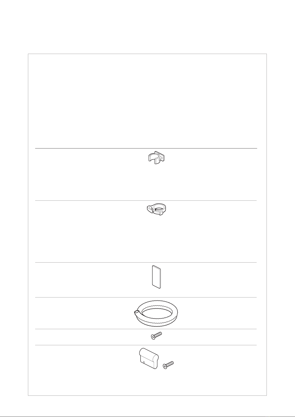
Beipacks
Accessory kit
Teil | Part Anzahl | Quantity
FCC3- 24/7 24/10 48/7 48/10
Clip für Rohr
Clip for duct
Ø 7 mm
Ø 10 mm
Ø 12...14 mm
Ø 16 mm
Ø 20 mm
50
–
6
6
6
–
50
6
6
6
50
–
6
6
6
–
50
6
6
6
Zugabfangung für Rohr
Strain relief element for duct
Ø 7 mm
Ø 10 mm
Ø 12 mm
Ø 14 mm
Ø 16 mm
Ø 20 mm
50
–
6
6
6
6
–
50
6
6
6
6
50
–
6
6
6
6
–
50
6
6
6
6
Abschlussplatte Clipschiene
End plate for clip rail 10 10 10 10
Wellrohr
Flexible conduit 1111
Schraube für Prolhalbzylinder
Screw for lock cylinder 1111
Blindzylinder
(nur bei Doppelschließanlage)
Dummy cylinder
(for double locking only) +
1111

Seite | Page 5von | of 28
Bodenplatte | Base plate
FCC3-48/7:
48x Ø 7 mm +6x Ø 12...20 mm
FCC3-48/10:
48x Ø 10 mm +6x Ø 12...20 mm
FCC3-24/7:
24x Ø 7 mm +6x Ø 12...20 mm
FCC3-24/10:
24x Ø 10 mm +6x Ø 12...20 mm
SystemübersichtSystemübersicht (Standard)(Standard)
System overview (standard)
Rohrverband- und
Kabelabfangung
Strain relief for duct
bundles and cables
Rohrabfangung
Clip rails for ducts
Spleißkassettensystem
für max. 54 Rastplätze (SC)
Fiber tray system
for max. 54 tray positions (SC)
Gehäuse
Cabinet
Sockel
Plinth
Kabelabfangung
Strain relief for cables
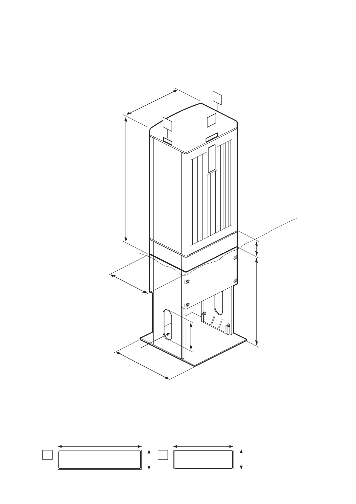
Seite | Page 6von | of 28
Leergewicht Gehäuse ca. 16 kg
Weight of empty cabinet about 16 kg
3 Maße Dimensions
Außenmaße (in mm)
Outer dimensions (in mm)
Gewicht
Weight
Kennzeichnungen: Standard [neutral]
Identication plates: [neutral] as standard
69
21
92
21
858
300
425
600
Sockel
Plinth
Gehäuse
Cabinet
Erdgleiche
Ground level
100
A
B
B
200200
444
Ø 70Ø 70
A B
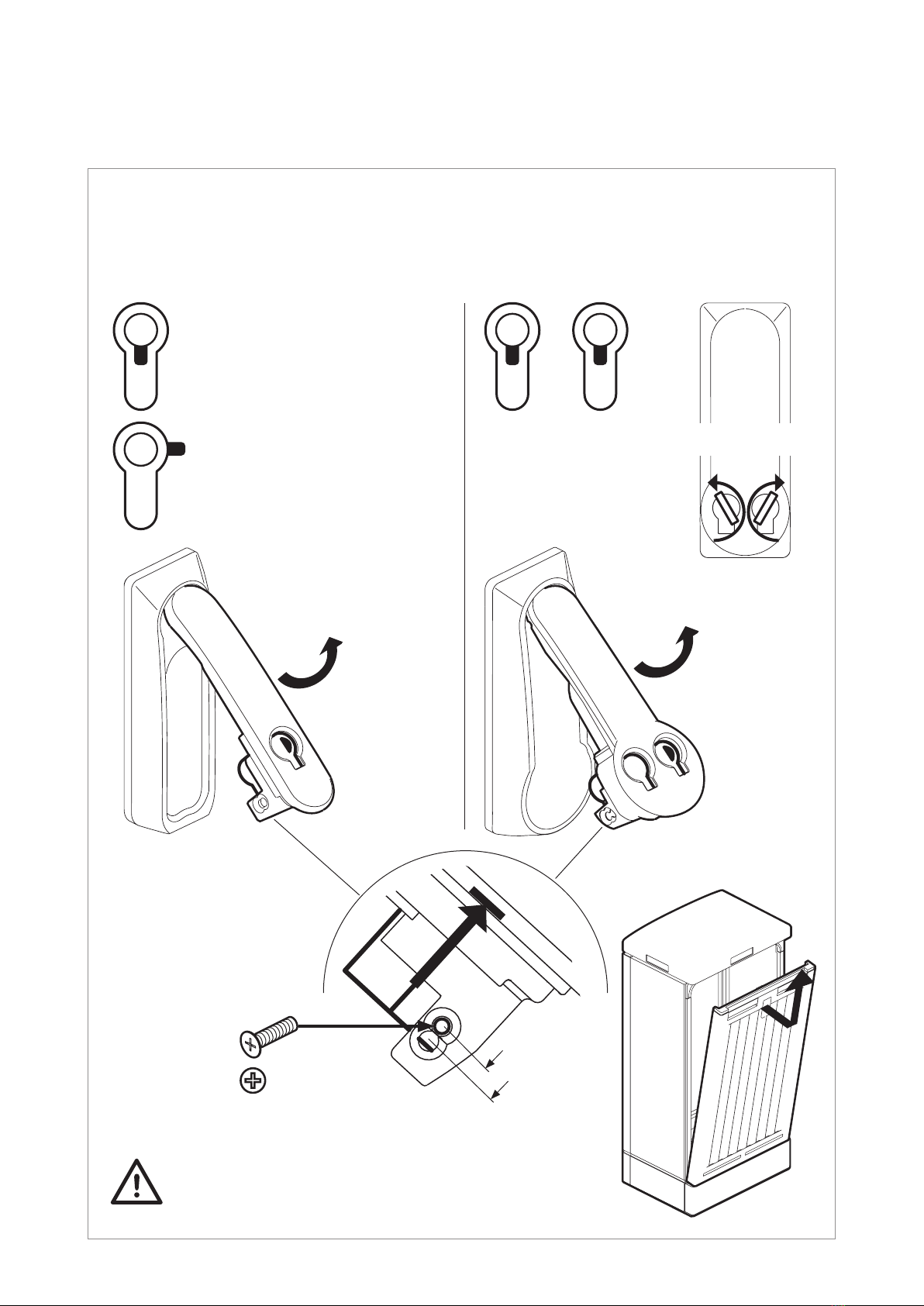
Seite | Page 7von | of 28
4 Schließsystem Locking system
(Standardschließungen) (Standard locking systems)
Schwenkhebel Doppelschließanlage
Swivel handle double locking mechanism
0° 0°
0°
Schwenkhebel Einfachschließanlage
Swivel handle single locking mechanism
Hinweise des Schließsystemherstellers beachten
Observe locking system manufacturer‘s notes
90° rechts
90° right side
StecktürStecktür
Slot-in doorSlot-in door
ÖffnungsrichtungÖffnungsrichtung
Opening directionOpening direction
(Schwenkhebel Metall)
(Swivel handle made of metal)
(Schwenkhebel Kunststoff)
(Swivel handle made of plastic)
Einstellung Prolhalbzylinder (nach DIN 18252)
Setting of lock cylinder (according to DIN 18252)
Zylinderlänge:
Length of cylinder:
a) 40 mm
b) 45 mm a)
b)
1x1x
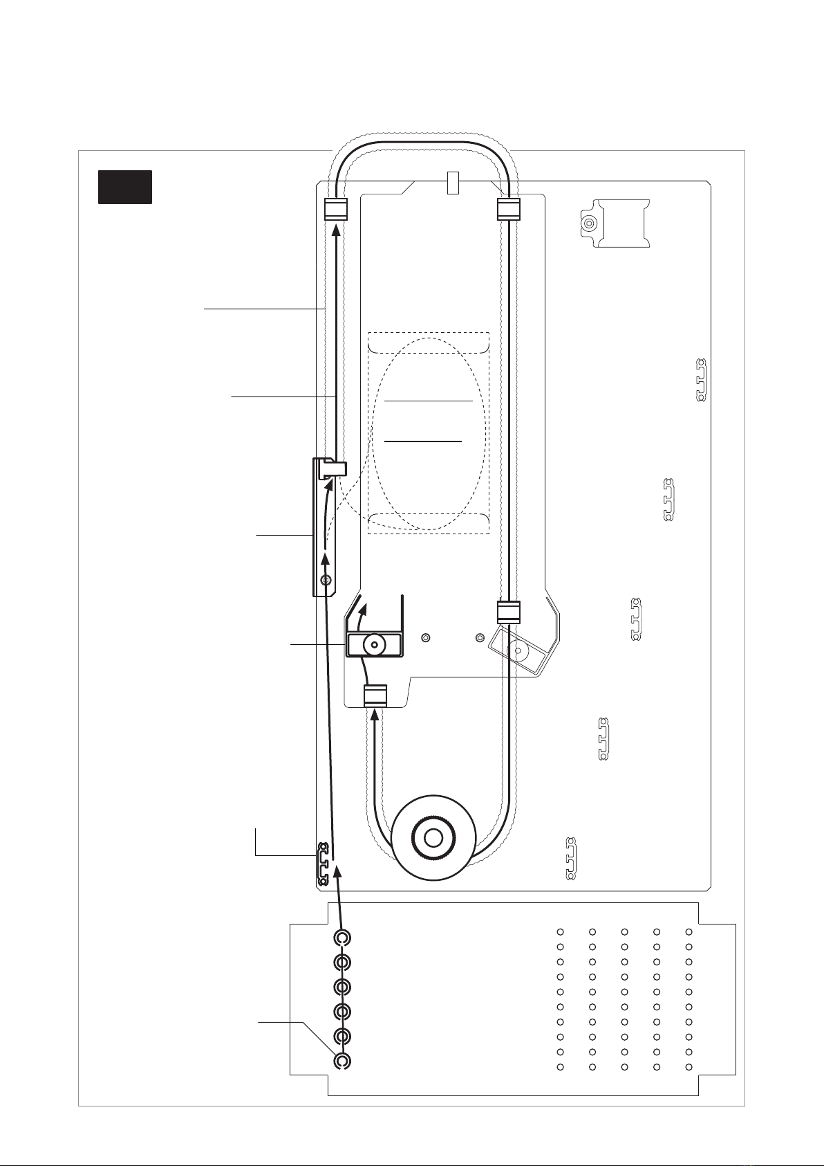
Seite | Page 8von | of 28
1
2
3
4
5
6
≥ Ø 10 mm
≥ Ø 16 mm
Loop
5 Führung und
Bodenmatrix Routing and
matrix of base plate
Bodenmatrix
Matrix of base plate
Bündeladern
Hauptkabel
Loose tubes
of trunk cable
Wellrohr
Flexible conduit
Kabelabfangung
Strain relief for cables
Rohrabfangung
Strain relief for ducts
Abfangung für Bündeladern
Strain relief for loose tubes
IN
Nachrüstsatz:
Bündelablage
Upgrade kit:
Loose tube
slack storage
(Vorschlag)
(Suggestion)

Seite | Page 9von | of 28
1
10
41
FCC3-xx/7:
≥ Ø 7 mm
FCC3-xx/10:
≥ Ø 10 mm
Bodenmatrix
Matrix of base plate
Rohre
Ducts
Klettband
Hook-and-loop tape
Kabel / Bündeladern
Cables / loose tubes
Rohrabfangung
Strain relief for ducts
Abfangung für Kabel oder
Bündeladern
Strain relief for cables
or loose tubes
1
2
3
4
5
8
7
6
5
4
3
2
1
21
50 30
Nur bei FCC3-48
For FCC3-48 only
+
5...8 zusätzlich bei FCC 48
5...8 additional for FCC 48
FCC3-24FCC3-48
OUT
(Vorschlag)
(Suggestion)

Seite | Page 10 von | of 28
6 Vorbereitungen Preparations
2FrontplattenFrontplatten 2a 2b entfernenentfernen
(Siehe Seite 22 + 23).
Remove the front panels Remove the front panels 2a 2b
(See page 22 + 23).
Gehäuseteile entfernen
Remove components of the cabinet
Gehäuse öffnen undGehäuse öffnen und
SpleißmodulSpleißmodul 1entfernen.entfernen.
Open cabinet and remove Open cabinet and remove
the tray unit the tray unit 1..
2b
2a
1
1
Seite | Page 11 von | of 28
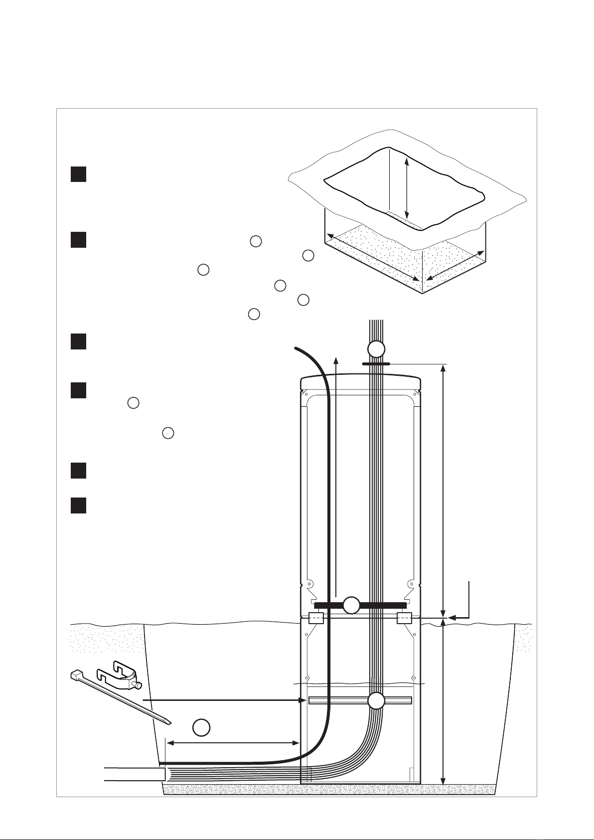
7 Montage
Sockel und Gehäuse Installation
of plinth and cabinet
1Baugrube ausheben, Grubensohle
abgleichen und verdichten.
Excavate a building pit,
adjust horizontal and compress it.
4Rohre und Kabel in das Gehäuse
führen D(siehe Bodenmatrix).
Integrate the ducts and cables
to the cabinet D
(see matrix of base plate).
Gehäuse aufstellen
Place the cabinet
Rohrverband auf Gehäusehöhe A
einkürzen und bis vor den Sockel auösen B.
An der Ankerschiene Cabfangen (optional).
Cut the duct bundle in cabinet height A
and open down with distance to the plinth B.
Fix the duct bundle to the C rail C(optional).
2
(min.)
Gehäuse ausrichten und Erdreich
beim Verfüllen lagenweise verdichten.
Align the cabinet, ll excavation pit
and compact layer by layer.
6
Frontplatten wieder anbauen.
Reinstall the front panels.
5
0...2 cm
über Erdgleiche
above ground
60 cm60 cm
~ 1.0 m
B
A
D
~ 4.0 m
3Kabel 4,0 m über Erdgleiche einkürzen.
Trim the cables 4.0 m above
the ground level.
ErdgleicheErdgleiche
Ground levelGround level
1.20 m1.20 m
0.70 m0.70 m
0.70 m0.70 m
C
~ 50 cm50 cm
(nicht im
Lieferumfang)
(not included)
Seite | Page 12 von | of 28
Kabel Centsprechend Hersteller-
vorgaben ab Höhe Abfangung absetzen.
Strip the cable Cin accordance
with the manufacturer‘s instructions.
Zentralelement an der
Zugabfangung Smontieren.
Install the strength member
to strain relief S.
8 Montage Hauptkabel Installation of trunk cable
8.1 Bündeladerkabel (metallfrei)(metallfrei) Loose tube cableLoose tube cable (non-metallic armoured)
C
Bündeladern fachgerecht glätten.
Straighten the loose tubes.
Kabel abfangen | Fasten the cable
S
Kabel mit Kabelbinder an der
Kabelabfangplatte befestigen.
Secure the cable to the strain
relief plate with a cable tie.
1
4
2
3
Seite | Page 13 von | of 28
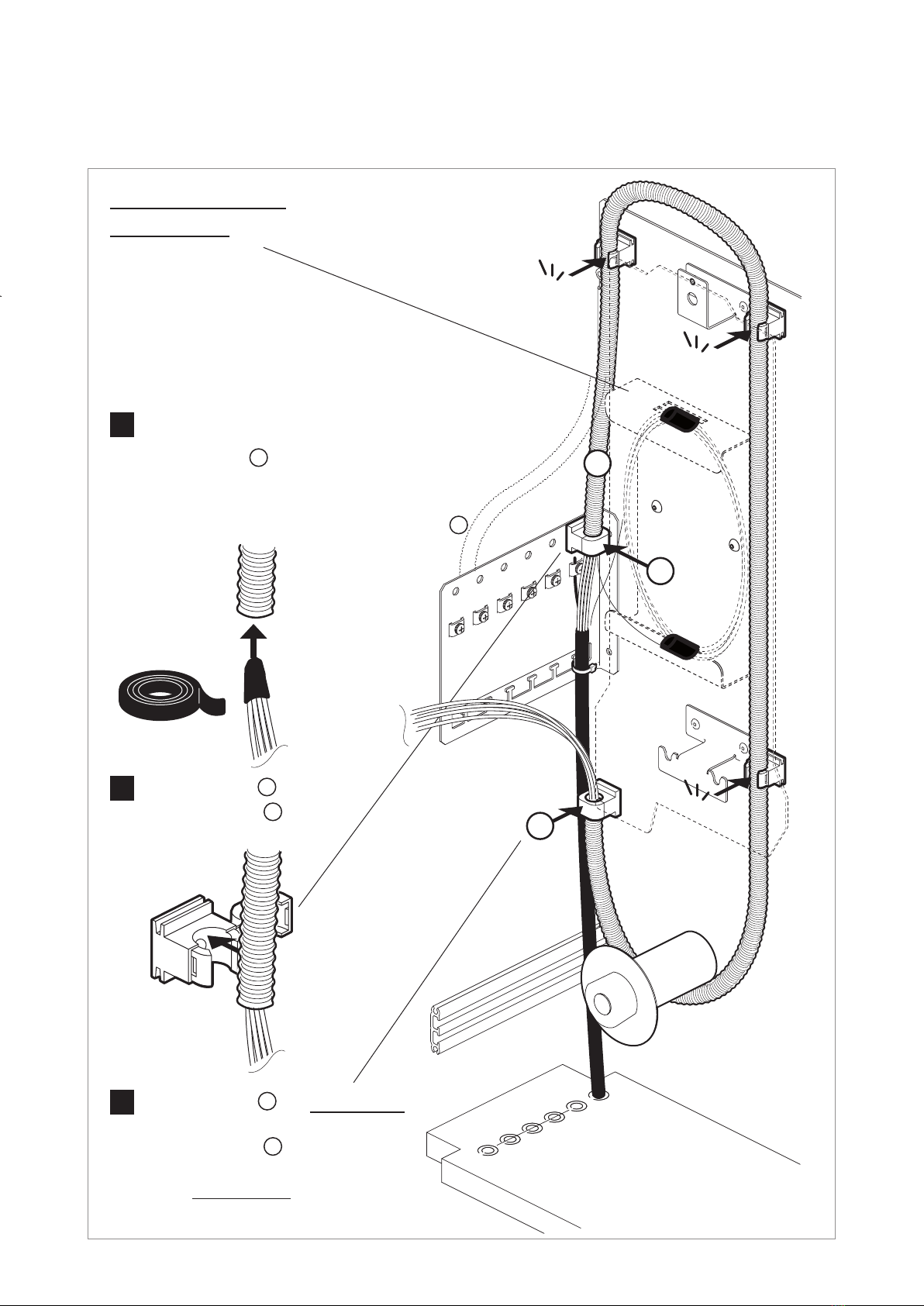
Bündeladerenden mit Isolierband
(Zubehör) umwickeln und in den
Flexschlauch Fführen.
Wrap the ends of loose tubes with
insulating tape (accessory) and
thread them through the exible conduit F.
Bündeladerführung | Loose tubes routing
Schlauchende E1 festsetzen.
Fasten the end E1
of the exible conduit.
F
Snap-in
Snap-in
Snap-in
1
2
E2
Schlauchende E2 am Spleißmodul
festsetzen (siehe Seite 18 + 19).
Fasten the end E2
of the exible conduit
to the ber tray unit
(see page 18 + 19).
3
E1
Nachrüstungsatz: Bündelablage / Loop
Upgrade kit: Loose tube slack storage / loop
(59.2519.11.00)

Seite | Page 14 von | of 28
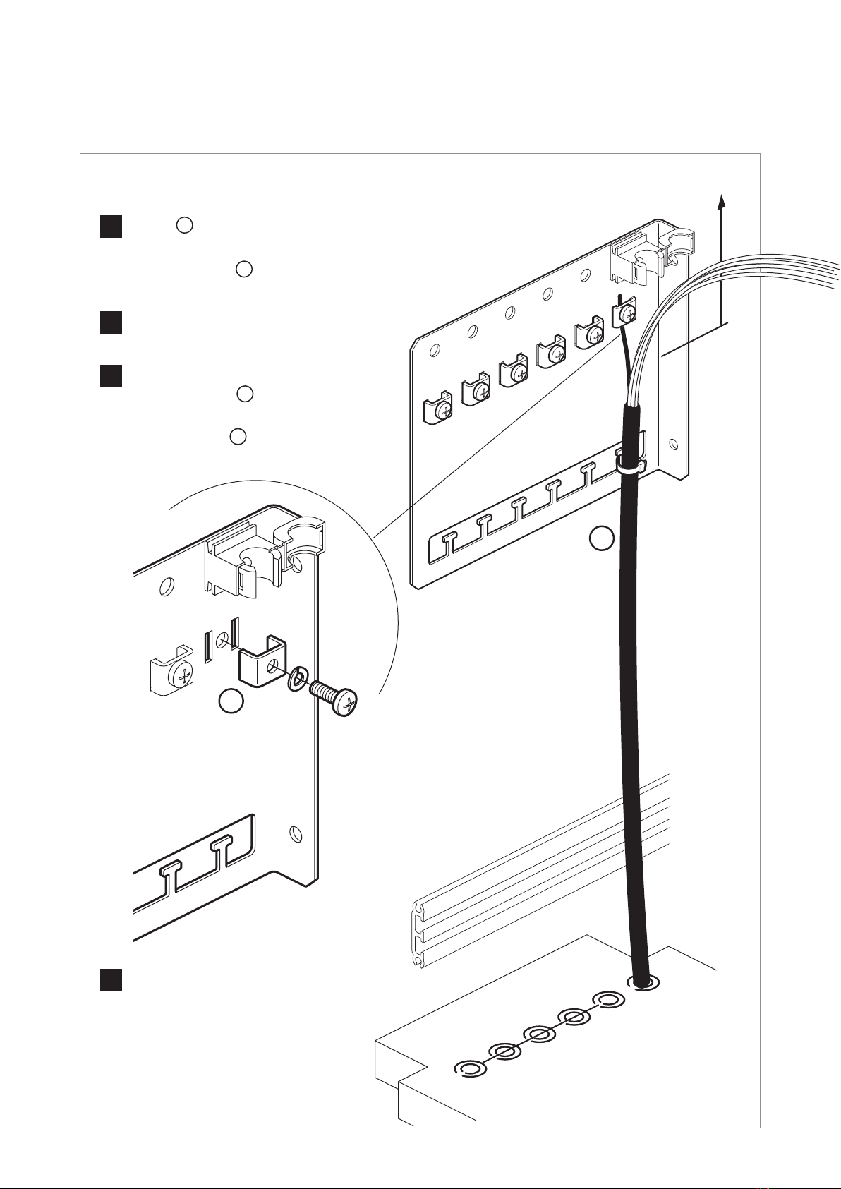
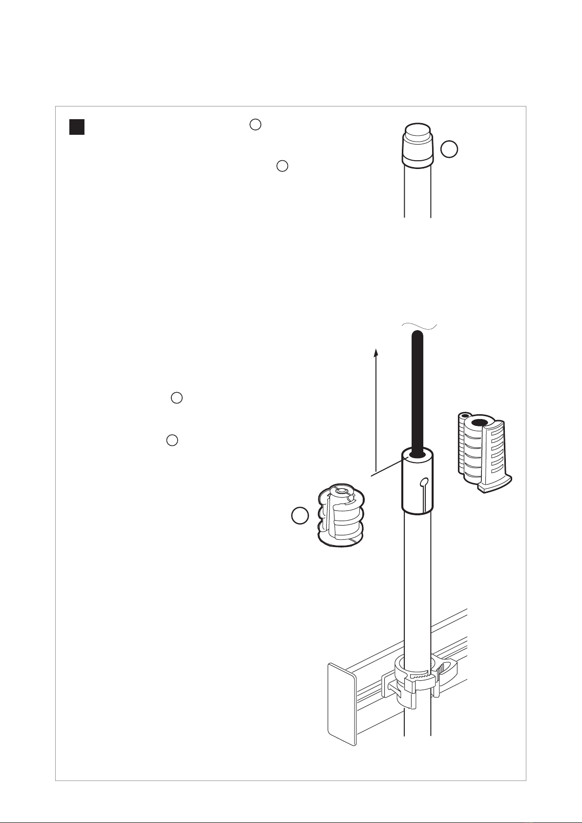
8.2 Minikabel mit Rohr Mini cable with duct
12 cm12 cm
S
C
Abdeckplatte Enach Montage aller
Clips an der Clipschiene befestigen.
Place the end plate Eafter mounting
all the clips.
E
Zugentlastung über dem Clip festsetzen.
Fix the strain relief element directly above the clip.
Rohr am eingeschobenen Clip Cbefestigen
und oberhalb der Clipschiene einkürzen.
Insert a clip Cinto the rail and snap the duct
into the clip. Trim the duct above the rail.
2
5
4
Rohr von unten durch die Bodenplatte führen.
Fed the duct from below through the base plate.
1
Zugentlastung Slocker vormontieren.
Loosely install the strain relief element S.
3
Montage Rohr | Installation of duct
Seite | Page 15 von | of 28
Minikabel in das Rohr einblasen und
Gas-Wasser-Blocker G(Zubehör)
gemäß Herstellervorgaben installieren.
Feed the cable through the duct and install
a gas-water-blocker G (accessory)
in accordance with the manufacturer‘s
instructions.
Kabel abfangen und führen:
siehe Seite 12 + 13.
Cable xing and routing:
see page 12 +13.
Montage Minikabel
Installation of mini cable
Unbelegtes Rohr mit Endstopfen 5(Zubehör)
oder Gas-Wasser-Blocker (Zubehör) gemäß
Herstellervorgaben abdichten.
Close an unused duct with an end cap 5 (accessory)
in accordance with the manufacturer‘s instructions.
5
6
G
5 m

Seite | Page 16 von | of 28
9 Montage
Verzweigerkabel Installation
of outbound cables
(Mikrokabel)(Mikrokabel) (micro cables)(micro cables)
Montage Rohr
Installation of duct
Siehe Seite 14.
See page 14.
Kabel in das Rohr einblasen und
Gas-Wasser-Blocker G(Zubehör)
gemäß Herstellervorgaben installieren.
Feed the cable through the duct and install
a gas-water-blocker G (accessory)
in accordance with the manufacturer‘s
instructions.
Montage Mikrokabel
Installation of micro cable
4 m
Abwechselnd
einschieben.
Insert alternating.
0...5 cm0...5 cm
Abhängig von Variante
Gas-Wasser-Blocker.
Depending on the version
of gas-water-blocker.
(Belegungsvorschlag)
(Layout suggestion)
G

Seite | Page 17 von | of 28
Mikrokabelführung
Routing of micro cables
Klettband
Hook-and-loop-tape
Zum Spleißmodul
(siehe Seite 18 + 19)
To the ber tray unit
(see page 18 + 19)
1
2
Siehe Seite 9.
See page 9.
3
4(FCC3-48)
5 (FCC3-48)
(Belegungsvorschlag)
(Layout suggestion)

Seite | Page 18 von | of 28
10 Spleißmodul Fiber tray unit
Wichtige HinweiseWichtige Hinweise
■Grundplatten sauber halten.
■Zur Reinigung von Kabeln, Fasern oder Kassettenteilen keine Lösungsmittel verwenden.
■Fasern vor dem Einlegen entsprechend den Herstellervorgaben reinigen (z.B. Isopropylalkohol).
■Mindestbiegeradien beachten.
■Absetzlänge beim Kamm (Bündeladerhalter) beachten.
■Bündeladern und Fasern vor dem Auegen der Fasern kennzeichnen.
■Anschneiden der Bündeladern nur mit zugelassenem Werkzeug ausführen.
■Mikrokabel dürfen nicht angeschnitten werden.
■Überkreuzen der Bündeladern und Fasern in den Grundplatten verhindern.
■Fasern ohne Spannung in die Faserführungskanäle unter alle Niederhalter legen.
■Falls beschaltete Fasern aus den Führungen gezogen wurden,
diese mit großer Sorgfalt vorsichtig zurückschieben.
■Geltende Sicherheitsbestimmungen beachten.
■Keep groove plates clean.
■Never use solvents to clean cables, bers or tray parts.
■Clean bers before tting in accordance with manufacturer‘s instructions (e.g. isopropyl alcohol).
■Maintain the specied bending radii.
■Observe the stripping length in the ridge system (loose tube holder).
■Mark the loose tubes and bers before tting the bers.
■Use only the approved tool for cutting open loose tubes.
■Do not cut open micro cables.
■Avoid crossing over loose tubes and bers in the groove plates.
■Place the bers without tension in the groove plate channels, underneath all retention tabs.
■If connected bers are pulled out of the groove plates, push them back in with extreme care.
■Relevant standards and guidelines must be observed.
Important notesImportant notes

Seite | Page 19 von | of 28
Kabel / Bündeladern entsprechend
Herstellervorgaben absetzen.
Strip the cables / loose tubes in accordance
with the manufacturer‘s instructions.
Fasern in den Kassetten ablegen: siehe Seite 20 + 21.
Place bers in the trays: see page 20 + 21.
Fasern
Fibers
4 3 2 1
1 2 3 4 5 6
8
7
6
5
4
3
2
1
9
(e.g. 42x Ø 3.4 mm)
Das Spleißmodul kann bei Bedarf entnommen werden (siehe Seite 10).
Torsionen unbedingt vermeiden!
The ber tray unit can be removed if required (see page 10).
Torsions must be strictly avoided!
A
2x2x
A
E2
4 mm
max. 25 mm

Seite | Page 20 von | of 28
11 Kassettensystem Fiber tray system
Grundplatte (Faserführungsplatte)
Groove plate (Fiber routing plate)
Die Fasern müssen sich
unter den Niederhaltern
benden.
Ensure that the bers are
underneath the hold-down tabs.
Fasern in den am Drehpunkt
der Kassette liegenden
Faserkanal einlegen.
Place the bers in the
ber channel at the
rotation axis of the tray.
Faserführung
Fiber routing
Kassettenbefestigung
Installation of the trays
Im rechten Winkel einrasten.
Snap in at 90°.
90°
11
2
3
4
5
6
170
40
19
(Maße in mm)
(Dimensions in mm)
Material: PC/ABS
Material: PC/ABS
This manual suits for next models
3
Table of contents
Popular Industrial Electrical manuals by other brands

Siemens
Siemens SITRANS LVS100 operating instructions

Murata
Murata GRM31CR61E106KA12 Series Reference sheet

Eaton
Eaton Power Defense PDC4X3TA800 Instruction leaflet

Murata
Murata GJM0335C1E8R6CB01 Series Reference sheet

C-COM Satellite Systems
C-COM Satellite Systems iNetVu MP- 80 user manual

Murata
Murata GRM188R61A824KA61 Series Reference sheet


