CBR-Test 50
24-9150
Original Instructions 7 9901X0237 Issue 5
Portable Appliance Tests (PAT)
All ELE designed products are tested for electrical safety prior to sale.
An electrical safety test label is fitted (usually adjacent to the mains input socket).
Should no label be found, please contact ELE Service Department quoting the serial
number of the equipment.
Organisations have an obligation to ensure equipment is maintained and is safe for
use. Regular PAT testing is one means of ensuring equipment continues to be
electrically safe.
Important: do not connect PAT leads to sensitive components such as PCBs,
control switches and the like.
DO NOT FLASH TEST ELECTRONIC EQUIPMENT.
If in doubt as to the most suitable connection point (which will usually be an
earth stud or an external earth connection) contact ELE Service Department for
assistance.
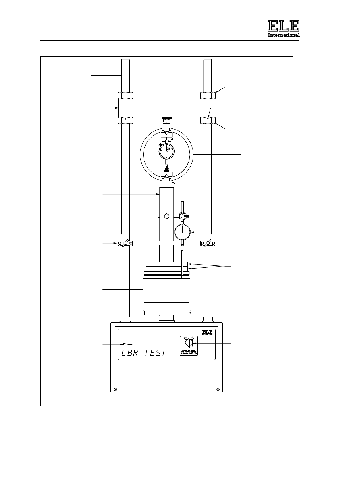
5 Controls (refer to figure 1)
5.1 Mains ON/OFF thermal trip switch (at the rear of the machine).
The thermal trip will fail repeatedly if an electrical fault occurs within the machine. The
fault must be located and rectified before commencing work with the machine.
5.2 Mains POWER light.
This illuminates to indicate that there is mains power to the machine and the Mains
ON/OFF switch is switched to ON.
5.3 DOWN-OFF-UP switch
This controls the platen movement. In the central position the drive motor is OFF.
When the machine is switched to run either up or down, the corresponding direction
indicator light will illuminate.
Important: ensure that the motor has stopped before reversing platen direction.
This may take approximately 5 seconds. Failure to allow the motor to stop
when changing platen direction may cause severe damage to the machine.
6 Operation
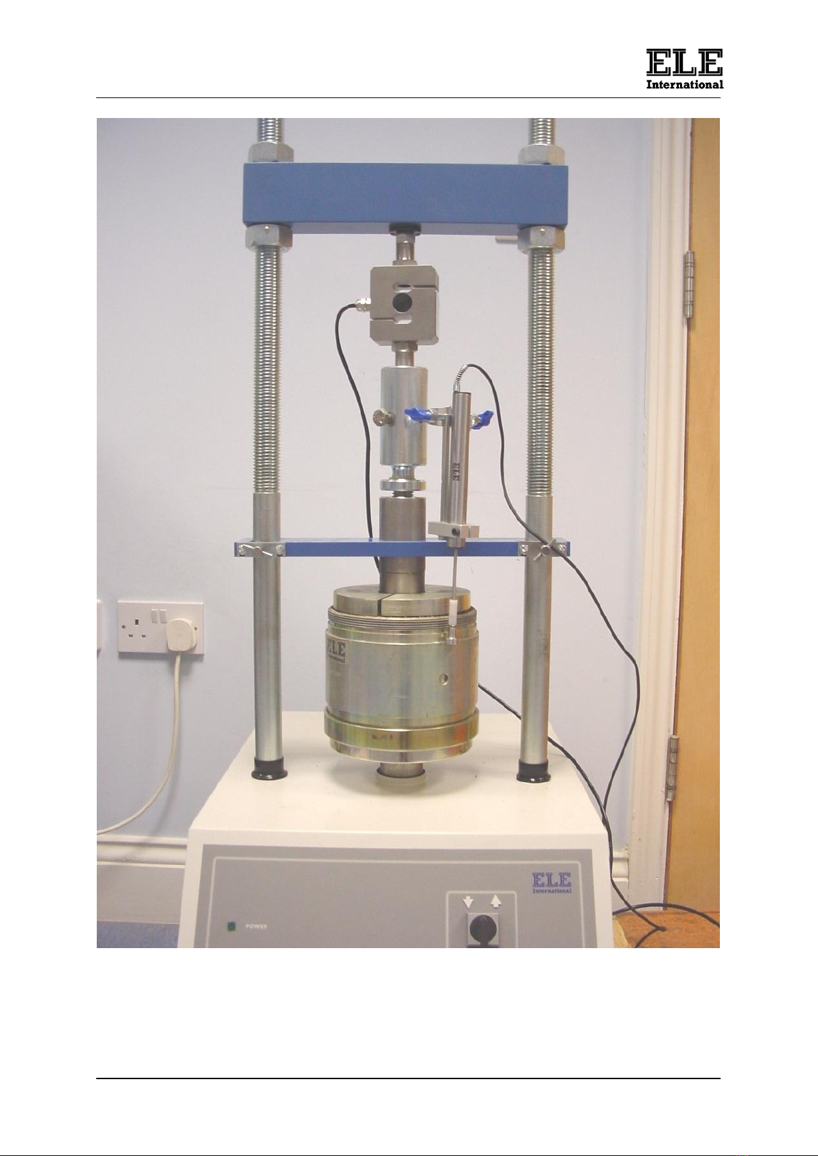
6.1 A typical analogue set up is shown in figure 1.
6.2 It is suggested that any test should be started with the platen set approximately 10
mm from the bottom of its travel.
6.3 Wind the platen clockwise to the bottom of its travel and then back anticlockwise for
approximately 3 or four turns. This will then set the platen at approximately the
suggested height.
6.4 Fit an ELE load ring (or load transducer if using in conjunction with the DSU) of the
desired capacity to the crosshead.
6.5 Position the crosshead at the height required by firstly slackening the nuts on either
side above the crosshead and then adjust the crosshead to the required height by
using the adjustment nuts below the crosshead. To ensure that the crosshead is
level, the alignment studs on the lower nuts should be located centrally and at the
front of the machine. Tighten the locking nuts using a spanner.