SecuControl FTL User manual

FTL Test Blocks
Reference Handbook
FTL-reference-en v.181

Copyright Notice
All information provided in this document is the property of SECUCONTROL .
SECUCONTROL grants its customers or potential customers the right to download,
copy, store and print this document for the sole purpose of assisting them in the correct
application of the products mentioned in this document.
All other uses of this document are expressely prohibited.
Intellectual Property Notice
This publication contains proprietary information under protection of the following
(among others) patents: DE 10 2005 025 108, DE 10 2008 016 388, US 7,271,357
and US 7,884,597.
Contents Disclaimer
Although the information and recommendations in this document are presented in
good faith and believed to be correct as of publication date, SECUCONTROL makes
no representations as to the completeness or accuracy thereof. In no event shall
SECUCONTROL be responsible for damages of any nature resulting from the use of
or reliance upon the contents of this document.
Continuous Improvements
Products developed by SECUCONTROL are continuously improved. The information
in this document may, therefore, be out of date.
Please make sure you have the latest release of this document before proceeding by
checking its name and revision code. This information is printed on the front cover
of this document, underneath the title. The latest release of this document can be
downloaded from www.secucontrol.com/downloads. Alternatively, you may contact
SECUCONTROL at any of the addresses provided on the rear cover of this document.

Contents
1 Introduction 1
The FTL Test Block .............................. 1
Key Features ................................. 1
Applicable Models .............................. 1
Unpacking ................................... 1
Part Number and Manufacturing Date Location ............... 2
Safety Symbols ................................ 2
General Safety Instructions .......................... 2
2 Principle of Operation 3
Closed Circuit ................................. 3
Open Circuit .................................. 3
Signal Injection ................................ 3
3 Application 5
Schematic Symbols .............................. 5
Typical Connection Schematic ........................ 6
4 Installation 7
Panel Cutouts, Drilling Plans and Mounting ................. 7
Wiring ..................................... 9
5 Operation 11
6 Technical Specifications 13
Electrical ................................... 13
Mechanical .................................. 14
Dimensional Drawings ............................ 14
7 Models Available 17
Number of banana jacks ............................ 17
8 Accessories 19
Adapters for use with Insulated Banana Plugs ................ 19
Adapters for use with Wide Test Leads .................... 19
i

ii CONTENTS
Jumper Cable ................................. 20
Current Measurement Probe ......................... 20
FTL 19” Rack Plates ............................. 21
Covers for 19” FTL Rack Plate Cutouts ................... 22
9 Spare Parts 23
Disconnect Pins ................................ 23
Dust Covers .................................. 23
Fitting Set ................................... 23
10 Ordering Information 25
Part Numbers ................................. 25
Available Configurations ........................... 25

1 Introduction
The FTL Test Block
The FTL is a test block for interfacing substation devices (protection relays, fault
recorders, revenue meters, . . . ) to the voltage and current transformers and to other
equipment on the system side of a power grid.
The FTL Test Block uses Disconnect Pins to isolate the substation devices from the
system side equipment. Once isolated, secondary injection can be performed using
banana jacks on the front side of the Test Block.
Key Features
•Finger-safe Test Block and Disconnect Pins increase safety during testing.
•Disconnect Pins are keyed to the corresponding parts of the Test Blocks, pre-
venting mistakes and errors during test.
•Extremely low internal resistance (<2 mΩ) helps reduce heat inside cabinets
and panels.
•Available in 8, 10, 12, 14, 16, 18 or 20 pole configurations.
Applicable Models
Information in this document applies to all FTL Test Blocks manufactured after May
2011.
Unpacking
Unpack the product carefully and make sure that all pertinent parts like dust covers
and screws are put aside so they will not be lost.
Check the contents against the packing list. If any of the contents listed are missing,
please contact SECUCONTROL immediately (see contact information at the rear cover
of this manual).
1

1. INTRODUCTION
Examine the product for any shipping damage. If the product is damaged, notify
the shipping company without delay. Only the consignee (the person or company
receiving the unit) can file a claim against the carrier for shipping damage.
Part Number and Manufacturing Date Location
Part number and manufacturing date are stated on a label on the right side of the Test
Block.
Safety Symbols
The following symbols are located on different parts of the equipment and in this
manual:
Paragraphs marked with this symbol contain information which,
if not properly followed, may cause damage to the equipment
and/or installation.
Paragraphs marked with this symbol contain information which,
if not properly followed, may cause personal injury or even
death.
General Safety Instructions
Installation and operation of the products described in this manual is only to be per-
formed by personnel that has been trained or is knowledgeable in substation protec-
tion, automation and control.
This instruction manual is an integral part of the scope of delivery and provides basic
instructions for installation and operation of the equipment here described. Shall ad-
ditional information be needed, please contact SECUCONTROL at any of the addresses
provided on the rear cover of this document.
Do not disassemble the Test Block. Correct alignment of internal parts is critical in
order to provide insulation and arch-avoidance.
The warranty will be void if the Test Block is disassembled (or otherwise handled
inappropriately). SECUCONTROL does not assume responsibility for any damages
arising out of mishandling of our products, including test blocks that have been disas-
sembled by parties other than SecuControl.
2
2 Principle of Operation
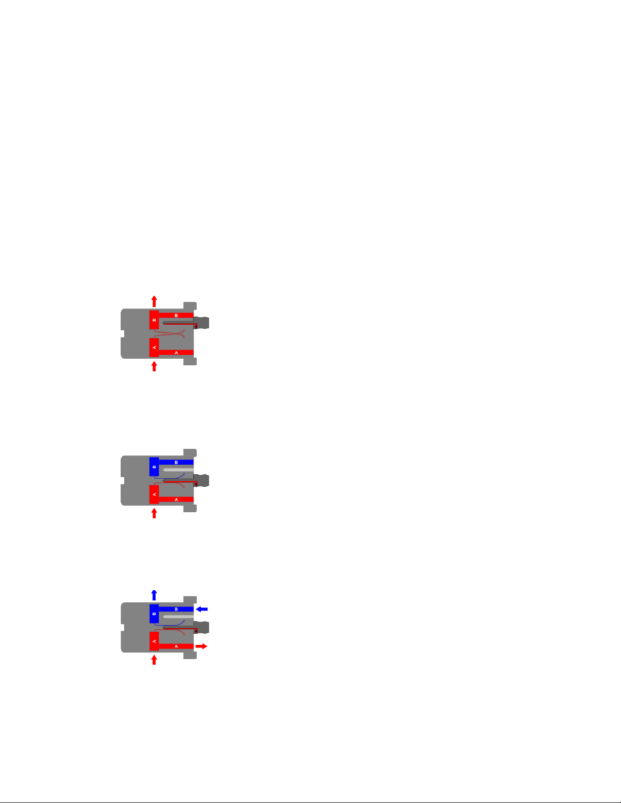
Closed Circuit
In the resting state the contacts of the FTL Test Block are
closed. In this situation, the signals from the system side
of the installation (side A) are connected to the measuring
and protection devices (side B).
Open Circuit
To open the Test Block’s contacts, the disconnect pins are
moved from the parking position to the test position. In
this situation, the devices on the B-side are insulated from
the installation side.
Signal Injection
With the disconnect pins in the test position, signal injec-
tion can be performed using the banana jacks on the front
side of the Test Block.
3

3 Application
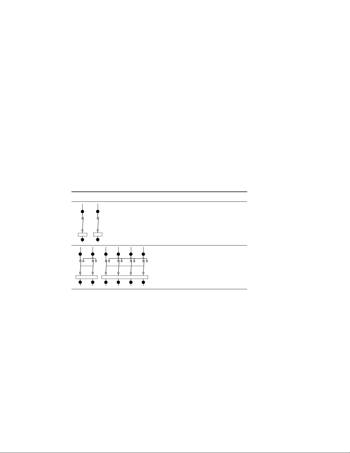
Schematic Symbols
Following symbols are suggested in order to represent the FTL Test Block in schematic
diagrams.
Symbol Description
S
V
Signal, Voltage (single pole)
- C
C - - C
- C -
- C -
C -
Current (2-pole, 4-pole)
5

3. APPLICATION
Typical Connection Schematic
3
2
1
N
V V V
C - - C C - - C C - - C
V
1
2
3
4
5
6
7
8
9
10
11
12
13
14
15
16
17
18
19
20
10 004 AA
6
4 Installation
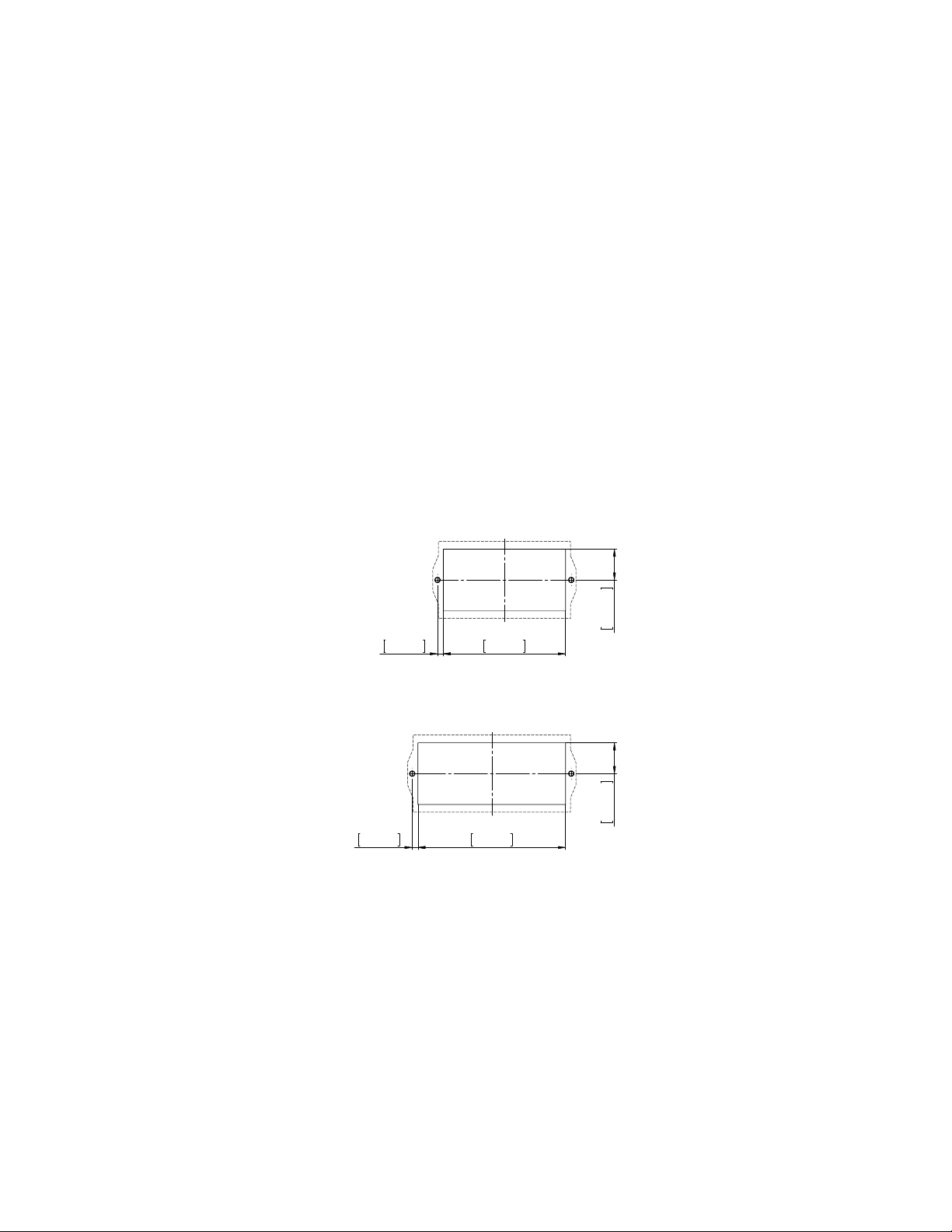
Panel Cutouts, Drilling Plans and Mounting
Use the provided M5x30 screws to fix the FTL Test Block onto the panel. The screws
should be tightened using a 4 mm hex drive.
8-pole Models
111mm
4.370in
5.2mm
0.205in
28mm
1.102in
10-pole Models
134mm
5.276in
5.2mm
0.205in
28mm
1.102in
7

4. INSTALLATION
12-pole Models
157mm
6.181in
5.2mm
0.205in
28mm
1.102in
14-pole Models
180mm
7.087in
5.2mm
0.205in
28mm
1.102in
16-pole Models
203mm
7.992in
5.2mm
0.205in
28mm
1.102in
18-pole Models
226mm
8.898in
5.2mm
0.205in
28mm
1.102in
8
Wiring
20-pole Models
249mm
9.803in
5.2mm
0.205in
28mm
1.102in
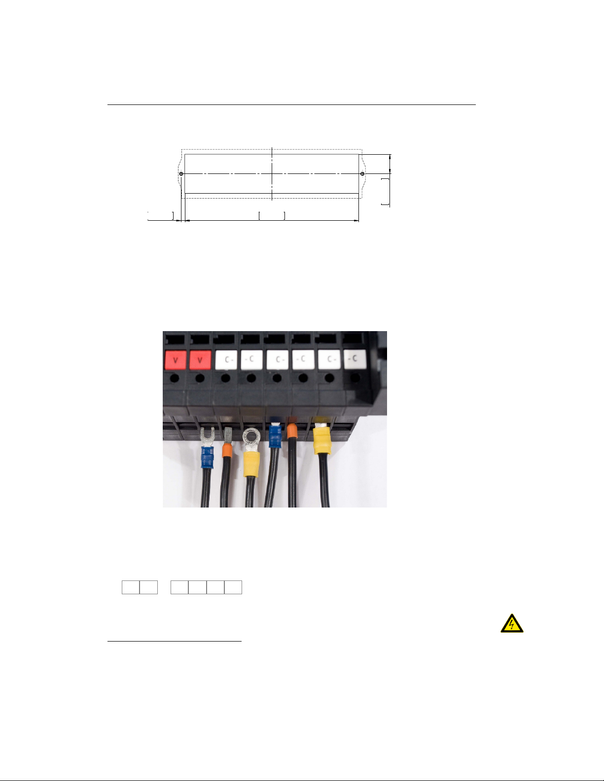
Wiring
Electrical connection terminals are located on the top and bottom of the FTL Test
Block. The connection terminals combine a screw in the center with a pressure plate,
accepting ring cable lugs, stripped wire or other crimp connectors.
Recommended wire gauge is from 1.5 mm2(AWG 16) to 4 mm2(AWG 12).
CTs should be wired to the terminals provided for this purpose (in 2- or 4-pole com-
binations) to ensure automatic short circuiting upon insertion of the Disconnect Pins.
The terminals designated for the connection of the CTs can be typically identified by
the C- -C or C- -C- -C- -C labeling1.
The panel equipments (protection relays, meters, fault recorders, etc) should be con-
nected to the device side terminals indicated by the odd-numbers (1, 3, 5, 7, . . . ), or
by the “b” suffix (1b, 2b, 3b, . . . ), depending on model.
1Custom labeling may show other symbols or use other colors.
9

4. INSTALLATION
The protection equipments (current and voltage transformers, breaker, etc) should be
connected to the system side terminals indicated by the even-numbers (2, 4, 6, 8, . . . ),
or by the “a” suffix (1a, 2a, 3a, . . . ), depending on model.
10

5 Operation
Handling of Disconnect Pins should be done using only its plastic part, since the
fingers may be connected to live equipment either via the test block or test equipment.
1. Remove the dust cover by sliding the cover up and then out.
2. Remove the FTL Disconnect Pins one-by-one from the parking position and
insert them into the corresponding circuit’s testing position.
There is no need to externally short-circuit the current transformers, since the
2- and 4- pole current Disconnect Pins have an integrated shorting bar which
will automatically short circuit the corresponding circuits before opening it.
Notice that the dust cover can’t be reattached to the Test Block if any of the
Disconnect Pins is in the testing position. This is intentional and provides a
visual flag that testing is being performed.
3. For signal injection, connect the test set via the banana jacks in the FTL Test
Block. This step is entirely based on your normal testing procedures, and should
be planned and carefully executed by a trained technician.
4. Once you are ready to resume normal operation, remove the Disconnect Pins
from the testing position and insert them back into the parking position.
5. Reattach the dust cover once all Disconnect Pins are returned to the parking
position.
11


6 Technical Specifications
Electrical
Current Withstand 30 A continuously
500 A for 1 second
Maximum voltage 600 V
Contact resistance ≤2 mΩ
Dielectric Withstand 3.0 kV RMS for 1 minute between adjacent
contact pairs and between any contact pair and
other metal parts
2.0 kV RMS for 1 minute between open con-
tacts when test pin is inserted
Voltage Impulse 3 positive and 3 negative impulses of 5 kV
peak, 1.2/50 µs, 0.5 J between adjacent contact
pairs and between all contact pairs and other
metal parts
Temperature Range −25 to +70 ◦C (−13 to +158◦F), storage
−25 to +55◦C (−13 to +131◦F), operation
UL94 Flammability Class V-0
Enclosure Protection IP20 without cover
IP50 with dust cover attached
FTL Test Blocks have been classified as electromagnetically benign and are therefore
excluded from the scope of the European Community Directive 2004/108/EC.
FTL meets or exceeds all requirements from ANSI / IEEE C37.90-2005.
13

6. TECHNICAL SPECIFICATIONS
Mechanical
# of poles 8 10 12 14 16 18 20
Weight (kg) 1.04 1.25 1.46 1.67 1.88 2.09 2.30
(lbs) 2.29 2.76 3.22 3.22 4.14 4.61 5.07
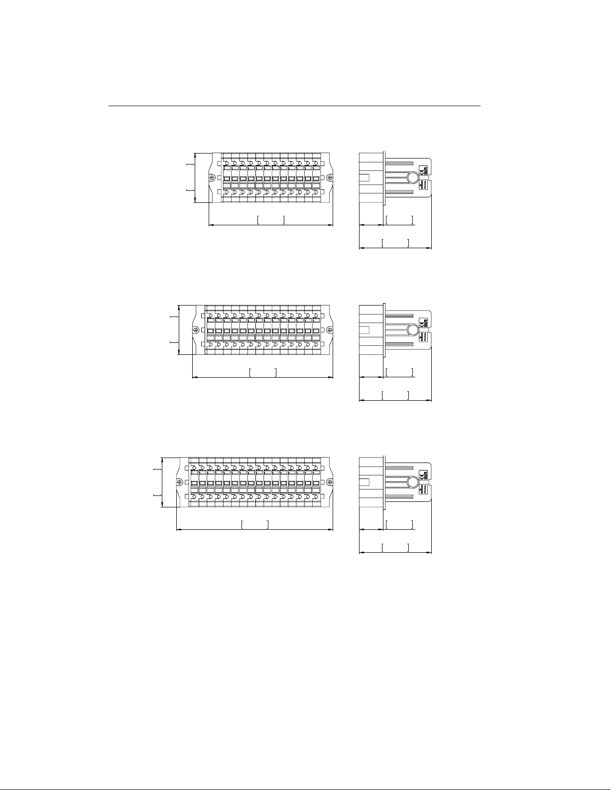
Dimensional Drawings
8-pole Models
130mm
5.118in
70mm
2.756in
34mm
1.339in
102mm
4.016in
10-pole Models
153mm
6.024in
70mm
2.756in
34mm
1.339in
102mm
4.016in
14
Dimensional Drawings
12-pole Models
176mm
6.929in
70mm
2.756in
34mm
1.339in
102mm
4.016in
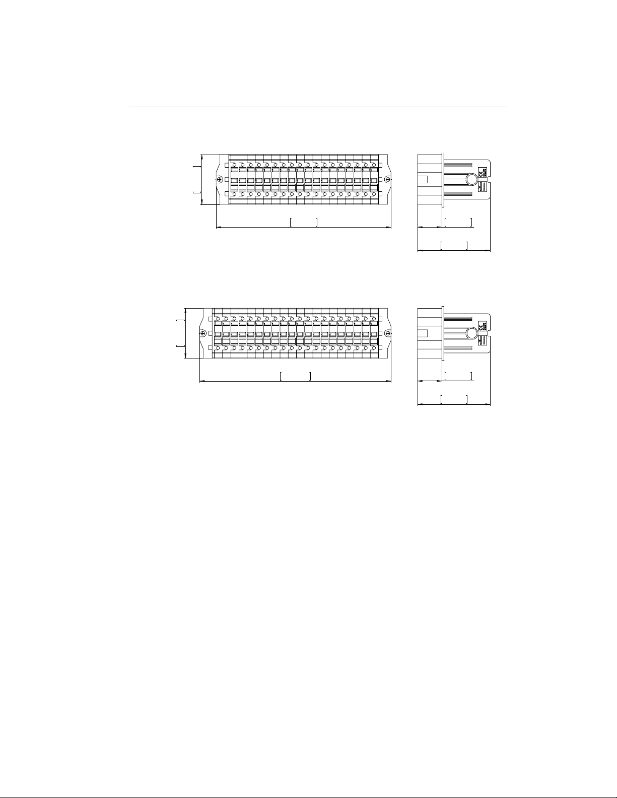
14-pole Models
199mm
7.835in
70mm
2.756in
34mm
1.339in
102mm
4.016in
16-pole Models
222mm
8.740in
70mm
2.756in
34mm
1.339in
102mm
4.016in
15
6. TECHNICAL SPECIFICATIONS
18-pole Models
245mm
9.646in
70mm
2.756in
34mm
1.339in
102mm
4.016in
20-pole Models
268mm
10.551in
70mm
2.756in
34mm
1.339in
102mm
4.016in
16
Table of contents
Other SecuControl Test Equipment manuals


