Electro-Music Klee Sequencer Instruction Manual

Building the electro-music Klee Sequencer
Issue: 6
Copyright © 2008, electro-music.com
This document may be freely reproduced and distributed in its un-altered form.
Cover photography by Tom Bugs
a

Building the electro-music Klee Sequencer
Table of Contents
Chapter 1: Planning Your electro-music Klee Sequencer…………………………1
Chapter 2: Designing the Front Panel……………………………………………...4
Chapter 3: Mounting Parts to the Front Panel……………………………………...9
Chapter 4: Strap Wiring the Front Panel………………………………………….22
Chapter 5: Building the Cables……………………………………………………40
Chapter 6: Installing the Panel/PCB Wiring………………………………………53
Chapter 7: Building the Boards……………………………………………………69
Chapter 8: Final Assembly of the electro-music Klee Sequencer…………………91
Chapter 9: electro-music Klee Sequencer Bring-Up Procedure…………………...97
Chapter 10: Calibrating the electro-music Klee Sequencer………………………..109
Appendices
Appendix A: Analogue Board Bill of Material…..........................................A1
Appendix B: Digital Board Bill of Material………..……………………….B1
Appendix C: Front Panel and Wiring Bill of Material…..………………….C1
i

1. Planning Your electro-music Klee Sequencer
Before you build your electro-music Klee Sequencer, it's a good idea to figure out what
features and functionality you may want. You will also want to give consideration to
panel layout and labeling, especially as to the labeling of switch positions, etc.
Most of the electro-music Klee sequencer functions are what could be considered as
"standard". In other words, without these standard functions, its functionality would be
limited as compared to the concept of the operation. Other features are more malleable.
The standard features are too numerous to mention here, but, instead we'll discuss the
features and functionality that are considered optional.
Optional Features
Optional Voltage Control Outputs
There are three standard voltage control outputs - Output A, Output A+B and Output B.
The voltage outputs are under control of the three Glide controls - Glide A, Glide A+B,
and Glide B.
The optional voltage control outputs are the same control voltages, but are tapped before
the glide circuit in the electro-music Klee Sequencer. Therefore, the glide controls will
not effect these outputs. These outputs are useful for various reasons. For example, you
may wish to control the cutoff of a filter with a slewed version Output A+B, yet control
the VCO passing through the filter with a non-slewed version of the same voltage.
The three optional outputs, A, A+B, and B, are provided on J3 of the Analog Board, on a
six pin connector which includes the standard outputs.
Variable Range Control Options
The Range Switch of the electro-music Klee Sequencer is an eight position switch that
allows the operator to set the maximum range of the programming pots. These ranges are
tuned certain musical intervals, as well as higher voltages. There may be an instance
where you would like to try other intervals other than what are supplied by the Range
Switch. There are four ways to implement a variable range feature.
•Option 1: Internal Variable Range Option
The Internal Variable Range Option consists of an additional variable range control
pot. When position 8 of the Range Switch is selected, the Variable Range Pot allows
you to set a continuously variable voltage as the maximum range of the programming
pots – in other words, you can set your own “interval” using this pot. The maximum
range of this pot can be selected by selecting a resistor of a particular value for R33
on the Analogue Board.
1

•Option 2: External Only Variable Range Option
The External Only Variable Range Option consists of an additional jack that accepts
an external positive voltage and an additional level control pot for this voltage. When
position 8 of the Range Switch is selected, the signal applied to the External Variable
Range Pot, as attenuated by the External Variable Range Level Pot, is applied as the
maximum voltage for the programming pots. Negative voltages can be applied
without harm, but the Klee will only react to positive voltages.
•Option 3: Auto Switching Internal/External Variable Range Option
This option will only work if you use either 1/4” jacks or 3.5 mm jacks with an n.c.
switch. It consists of this jack and an additional Variable Range/External Level
control. With no plug inserted into the jack, it operates identically to Variable Range
Option 1. When a plug is inserted into the jack, the signal level on the plug is applied
as with Option 2.
•Option 4: Manually Switched Internal/External Variable Range Option
This option will work with any type of jack. It adds the jack, the variable pot, and an
additional SPDT ON-ON switch. This allows the functionality of Option 3, except
now the position of the SPDT ON-ON switch will determine if the maximum voltage
is supplied internally by the Klee, or by externally applied positive voltage.
Optional External Load Enable Switch
The Optional External Load Enable Switch is an option that can be added to the front
panel. It merely consists of connecting the external load jack to a SPST On-Off switch,
and connecting the output of the switch to the External Load line. This feature makes it
handy for connecting/disconnecting an external load signal that is applied to the External
Load Jack.
5V Gate and Trigger Levels vs 10V Gate and Trigger Levels
The Klee's standard schematic configuration is to provide 5V range gate and trigger
levels. However, many people (and systems!) require higher levels. So, before you
begin to put your electro-music Klee Sequencer board set together, you should be sure
which level you want to go with. This will determine what value of resistors you use in a
certain section of the Digital Board.
Automated Range Switch Data Inputs
Pads are supplied on the Analogue PCB to allow external digital signals to select the
voltage range of the Klee Sequencer, in effect “over-riding” the Range Switch. These
signals would have to be 0V for low and 15V for high (12V if the Klee is operated from a
twelve volt supply). The interface consists of three digital inputs which control range
positions 1 through 8.
2

Procuring Parts
Get Good Quality Parts
Sometimes, when you’re looking for and buying parts, you may see a “good” deal on
surplus parts. With the ICs, you’re probably OK. The pots, maybe so. The switches?
Do not risk it. There are a lot of switches on the electro-music Klee. A bad switch will
ruin things very quickly for you. It is highly recommended you buy good quality
switches from the start from a known good manufacturer – NKK, ALPS, etc. Don’t buy
“generic” switches that do not have a manufacturer listed. You will regret it. In
particular, don’t scrimp on the momentary switches (the Manual Step and Manual Load
switches). There are cheaply priced momentary switches out there, usually under a
buck. There’s a reason they’re cheaply priced. Don’t do it.
Wire is another thing to consider, quality-wise. Old corroded wire, or wire with cheap,
easily melted insulation is something that should be avoided.
Jacks are another thing that should be considered on the “known” good list.
When you see a note about 0.1% resistors, we’re not whistling Dixie. If you do not use
0.1% resistors where indicated, make an effort to *match* the resistors used to 0.1%.
To Use Connectors or Hardwire?
The Klee PCB board set has been set up to interface with the front panel through wire
harnesses and sockets. This makes assembly and troubleshooting much more of a breeze
than hardwiring the connections. It adds some time to construct the cables, but saves in a
lot of time and effort down the road. The connectors do not have to be used – as
indicated, things can be hardwired. But, the connector system is highly recommended.
Selecting a Power Supply
Power Requirements
The electro-music Klee Sequencer has been tested using a +/- 12V power supply. It may
or may not require an adjustment of the 6K8 current limiting LED resistors – 4K7 will
work if brightness is an issue. However, the Klee has been most extensively tested at
+/15V operation and it is generally recommended.
The electro-music Klee Sequencer draws around 100 mA per voltage rail at +/-15V
operation, with a power dissipation of approximately 1.5 Watt per rail (3W total). A
linear supply can be used, but it is possible to use it with an appropriate switching supply.
In the case of a switching power supply, it is recommended that one use ferrite beads on
the power supply lines connecting to the Klee Sequencer.
3

2. Designing the Front Panel
It’s Your Klee – Do What You Wanna Do
The operating console of any piece of gear is probably the most important part of the
design, and, with the electro-music Klee Sequencer, that is left totally in your capable
hands. The front panel of the Klee Sequencer is its operating console, and you will find
that is where a good 90% of your build time is spent. After that, that’s where 100% of
your operating time will be spent, so think long and hard about how you want it to be
arranged.
Give consideration to ergonomics – don’t put things so close together that you have to
hold your tongue just right to change one setting whilst not bumping any other settings.
Don’t put jacks in places where a plug inserted into one of them will inhibit your access
to controls. Make sure the layout and flow makes sense to you. In general, this is the
usual drill you would apply to any project of yours.
Now, you may be thinking “That’s all well and good, but what flippin’ controls go on the
damn thing in the first place?”
That’s cool. That’s a cool question. The Klee Sequencer has a number of controls most
sequencers have, but it has a few that are perhaps not so common.
So, we’re going to introduce you to two things right now – the first thing are the controls
that allow you to control your electro-music Klee Sequencer; the second thing is this is
the first of many, many tables we’re going to inflict upon you over the course of this
document.
The tables consist of the types of controls, connectors and indicators that make up the
Klee interface to the world. Each table will list the control, and what the function of that
control is. This may help you to determine where you want to place things. Another
recommended tome is the “Know the Klee” section of the electro-music Klee Sequencer
Operating Manual. This will hopefully fill in any gaps of understanding that may arise
from these short, curt tables.
So, without further ado, the tables……..
4

Table 2-1: Potentiometers and Their Functions
Label Function
Stage 1 Programming Pot - Adjusts the voltage of Stage 1
Stage 2 Programming Pot - Adjusts the voltage of Stage 2
Stage 3 Programming Pot - Adjusts the voltage of Stage 3
Stage 4 Programming Pot - Adjusts the voltage of Stage 4
Stage 5 Programming Pot - Adjusts the voltage of Stage 5
Stage 6 Programming Pot - Adjusts the voltage of Stage 6
Stage 7 Programming Pot - Adjusts the voltage of Stage 7
Stage 8 Programming Pot - Adjusts the voltage of Stage 8
Stage 9 Programming Pot - Adjusts the voltage of Stage 9
Stage 10 Programming Pot - Adjusts the voltage of Stage 10
Stage 11 Programming Pot - Adjusts the voltage of Stage 11
Stage 12 Programming Pot - Adjusts the voltage of Stage 12
Stage 13 Programming Pot - Adjusts the voltage of Stage 13
Stage 14 Programming Pot - Adjusts the voltage of Stage 14
Stage 15 Programming Pot - Adjusts the voltage of Stage 15
Stage 16 Programming Pot - Adjusts the voltage of Stage 16
Glide A Adjusts the glide of Voltage Output A
Glide B Adjusts the glide of Voltage Output B
Glide A+B Adjusts the glide of Voltage Output A+B
Random Level Adjusts the level of the applied random source voltage
Random Reference Adjusts the threshold at which the applied random source voltage,
as adjusted by Random Level, will create a digital ‘1’ to be
inserted into the bit pattern at the rising edge of the clock.
Optional Variable
Range Control Allows adjustment of a variable voltage range to be applied as a
maximum range voltage for the programming pots.
Total Number of Potentiometers: 21 or 22 (if Variable Range Option is installed)
5

Table 2-2: Toggle Switches and Their Functions
Label Function
Pattern Switch 1 Programs a 1 or 0 for pattern bit 1
Pattern Switch 2 Programs a 1 or 0 for pattern bit 2
Pattern Switch 3 Programs a 1 or 0 for pattern bit 3
Pattern Switch 4 Programs a 1 or 0 for pattern bit 4
Pattern Switch 5 Programs a 1 or 0 for pattern bit 5
Pattern Switch 6 Programs a 1 or 0 for pattern bit 6
Pattern Switch 7 Programs a 1 or 0 for pattern bit 7
Pattern Switch 8 Programs a 1 or 0 for pattern bit 8
Pattern Switch 9 Programs a 1 or 0 for pattern bit 9
Pattern Switch 10 Programs a 1 or 0 for pattern bit 10
Pattern Switch 11 Programs a 1 or 0 for pattern bit 11
Pattern Switch 12 Programs a 1 or 0 for pattern bit 12
Pattern Switch 13 Programs a 1 or 0 for pattern bit 13
Pattern Switch 14 Programs a 1 or 0 for pattern bit 14
Pattern Switch 15 Programs a 1 or 0 for pattern bit 15
Pattern Switch 16 Programs a 1 or 0 for pattern bit 16
Gate Bus Switch 1 Directs signal to Gate Bus 1, 2 or 3 from Step 1
Gate Bus Switch 2 Directs signal to Gate Bus 1, 2 or 3 from Step 2
Gate Bus Switch 3 Directs signal to Gate Bus 1, 2 or 3 from Step 3
Gate Bus Switch 4 Directs signal to Gate Bus 1, 2 or 3 from Step 4
Gate Bus Switch 5 Directs signal to Gate Bus 1, 2 or 3 from Step 5
Gate Bus Switch 6 Directs signal to Gate Bus 1, 2 or 3 from Step 6
Gate Bus Switch 7 Directs signal to Gate Bus 1, 2 or 3 from Step 7
Gate Bus Switch 8 Directs signal to Gate Bus 1, 2 or 3 from Step 8
Gate Bus Switch 9 Directs signal to Gate Bus 1, 2 or 3 from Step 9
Gate Bus Switch 10 Directs signal to Gate Bus 1, 2 or 3 from Step 10
Gate Bus Switch 11 Directs signal to Gate Bus 1, 2 or 3 from Step 11
Gate Bus Switch 12 Directs signal to Gate Bus 1, 2 or 3 from Step 12
Gate Bus Switch 13 Directs signal to Gate Bus 1, 2 or 3 from Step 13
Gate Bus Switch 14 Directs signal to Gate Bus 1, 2 or 3 from Step 14
Gate Bus Switch 15 Directs signal to Gate Bus 1, 2 or 3 from Step 15
Gate Bus Switch 16 Directs signal to Gate Bus 1, 2 or 3 from Step 16
Merge 1 Switch Merges Gate Bus 1 adjacent gates and triggers
Merge 2 Switch Merges Gate Bus 2 adjacent gates and triggers
Merge 3 Switch Merges Gate Bus 3 adjacent gates and triggers
Bus 1 Load Switch Enables pattern re-load when Bus 1 transitions to high
Clock Enable Switch Connects/Disconnects clock input
Rand/Pat Switch Switches between random and programmed pattern mode
8X2/16X1 Switch Switches between two 8 stage patterns or one 16 stage pattern
Invert B Switch Enables inversion of Register B recirculated data
Optional External
Load Enable
Enables/Disables the external load signal applied to the External
Load Jack
6

Label Function
Optional
External/Internal
Range Switch
Selects between an applied external voltage and an internal
variable range voltage to be applied as the maximum range of the
programming pots.
Total Number of Toggle Switches: 40 Standard, 2 more with available Options
Table 2-3: Momentary Pushbutton Switches and Their Functions
Label Function
Manual Load Loads programmed pattern into shift register
Manual Step Advances shift register one step with each key press
Total Number of Momentary Pushbutton Switches: 2
Table 2-4: Rotary Switch and Its Function
Label Function
Range Selects maximum range of programming pots (eight position)
Total Number of Rotary Switches: 1
Table 2-5: Jacks and Their Functions
Label Function
A Output Outputs voltage pattern generated by section A (first 8 stages)
B Output Outputs voltage pattern generated by section B (second 8 stages)
A+B Output Outputs summed A+B pattern signal (all 16 stages)
Master Gate Outputs constant gate signal synchronous with clock
Master Trigger Outputs constant trigger signal synchronous with clock
Bus 1 Gate Outputs Gate Bus 1 gate signal
Bus 1 Trigger Outputs Gate Bus 1 trigger signal
Bus 2 Gate Outputs Gate Bus 2 gate signal
Bus 2 Trigger Outputs Gate Bus 2 trigger signal
Bus 3 Gate Outputs Gate Bus 3 gate signal
Bus 3 Trigger Outputs Gate Bus 3 trigger signal
Clock Input Accepts clock signal
External Load In Accepts pulse signal to initiate pattern load on rising edge
Random In Accepts signal from which random patterns are generated
Optional A Output Outputs voltage pattern generated by section A (first 8 stages)
Not affected by Glide Control A
Optional Aux B
Output Outputs voltage pattern generated by section B (second 8 stages)
Not affected by Glide Control B
Optional Aux A+B
Output Outputs summed A+B pattern signal (all 16 stages)
Not affected by Glide Control
Optional Variable
Range Input Accepts an external positive voltage input and applies that voltage
as the maximum programming pot range.
Total Number of Jacks: 14 standard, 4 more available as options.
7

Table 2-6: LED Indicators and Their Functions
Label Function
Pattern Bit 1 Indicates active bit/stage 1
Pattern Bit 2 Indicates active bit/stage 2
Pattern Bit 3 Indicates active bit/stage 3
Pattern Bit 4 Indicates active bit/stage 4
Pattern Bit 5 Indicates active bit/stage 5
Pattern Bit 6 Indicates active bit/stage 6
Pattern Bit 7 Indicates active bit/stage 7
Pattern Bit 8 Indicates active bit/stage 8
Pattern Bit 9 Indicates active bit/stage 9
Pattern Bit 10 Indicates active bit/stage 10
Pattern Bit 11 Indicates active bit/stage 11
Pattern Bit 12 Indicates active bit/stage 12
Pattern Bit 13 Indicates active bit/stage 13
Pattern Bit 14 Indicates active bit/stage 14
Pattern Bit 15 Indicates active bit/stage 15
Pattern Bit 16 Indicates active bit/stage 16
Clock Indicates clock rate
Master Gate Bus Indicates gate present on Master Gate Bus
Gate Bus 1 Indicates gate present on Gate Bus 1
Gate Bus 2 Indicates gate present on Gate Bus 2
Gate Bus 3 Indicates gate present on Gate Bus 3
Random Reference Indicates random signal has crossed reference and will generate a
“1” if a rising clock signal is present
Total Number of LEDs: 22
General Recommended Guidelines
We’re not here to tell you how you should lay out your Klee panel. In fact, if you want to
emboss strawberries and leprechauns on the panel, power to you. However, there are
some things we would consider helpful:
•Try to keep the pattern LEDs clear of other LEDs. For example, if you put the
gate bus LEDs in line with the pattern LEDs, it may be hard to tell where your
pattern ends and the gate bus begins.
•It’s helpful to align the pattern switches, programming pots, pattern LEDs, and
gate bus switches in some order so you know which stage each is associated with.
•If you run out of room on your panel, the clock LED could be sacrificed – it
essentially gives the same indication as the Master Gate Bus LED – there’s only a
2 microsecond delay between the two, which is far less latency than anyone of
non-superhuman/bionic capabilities can detect.
•Rotary pots are good for easy adjustment. Slider pots are excellent because you
can spot exactly where your settings are without peering at the little dots on your
rotary pot knobs. Either is good. This manual is rotary-pot heavy, but don’t rule
out sliders if you have the technology to put them into your panel.
8

3. Mounting Parts to the Front Panel
This section assumes you’ve already stamped, drilled, chiseled, nibbled or sledge-
hammered a slab of material into a front panel. Or, perhaps, you’ve even ordered from a
panel supply house a panel you’ve designed on your computer. In any event, you’ve got
it in your mitts and you’re ready to build.
Preparation
Set Some Landmarks
By now, you’ve probably realized that there are a lot of components on the electro-music
Klee Sequencer front panel. Really, the only time during the build when you’ll be
looking at your panel from the pretty, labeled front side is when you’re orienting the parts
and calibrating the thing. The rest of the time, you’ll be looking at the ugly, hidden part
behind the panel. This is the side that tells you nothing and can potentially lead you into
the deadly trap of Wiring Things Wrong. Why? Because, after a while, you’ll begin to
confuse which pot is which or which switch is what as you wire the thing up. Instead of
constantly looking at the front of the panel to make sure you really are soldering wire
where you want to, it’s a good idea to use a permanent marker or use some other labeling
method to mark the part positions on the rear of the panel. So, do it now, before you
forget. Remember, the world of the back of the panel is a bizarre universe where
everything is backwards – left is right, right is wrong, clockwise is anticlockwise and up
is often down. Mark the stage numbers, mark the label of the switch, mark the positions
of the switch (“Merge On”, “Invert B”, etc.). You’ll be glad you did, says the Voice of
Experience.
Orienting, Testing and Mounting the Parts
Some parts, particularly the SPST ON-OFF switches must be mounted with a particular
orientation to match how you have your panel labeled. It’s your Klee, so it doesn’t
matter to you, the operator, if the Gate Bus Merge 1 Switch will be flipped “up” to be in
the Merge position, or flipped down to be in the Merge position, as long as it agrees with
your front panel labeling. But, it matters to the switch.
The parts most sensitive to orientation, as mentioned, are the SPST ON-OFF switches,
and there are a lot of them. The pattern switches, the merge switches, the enable
switches, the Gate Bus 1 Load switch, and the mode switches are all of this variety. The
gate bus switches don’t really care at this point which way you mount them – the
orientation of if they flip up or down is in how you wire the things up later. The same
goes for the Invert B Switch.
So, break out your SPST ON-OFF switches and take a look at them. On the rear of each
switch are two terminals. These terminals are either shorted (closed) or open
9

(umm…open). It’s hard to tell which position is which. Some manufacturers of switches
may mark it on their terminals, others may not. You decide which is right, and which in
an illusion, to quote the Moody Blues.
How do you do this? It takes an ohmmeter or a continuity tester, or, better yet, a DMM
with a continuity tester built in. The kind of continuity tester that beeps when you have a
short (closed) circuit is by far the best, because your ears will let you know immediately
which position the switch is in, instead of having to peer at a meter while holding test
leads to the two terminals.
Connect one test lead of the ohmmeter/continuity tester/DMM to one terminal of the
switch, and connect the other lead to the other terminal of the switch. Flip the switch into
one position – if the DMM/Ohmmeter reads zero Ohms or close to zero Ohms, or your
continuity tester puts out a long tone, that’s the closed position. If your DMM/Ohmmeter
reads infinite resistance or your continuity tester stays silent, that’s the open position of
the switch. Flip the switch to the opposite position. You should now get the opposite
reaction from your instrument – if the switch was previously closed, it better now read
open and vice versa. If there is no change, you either have the wrong type of switch or
it’s a bad switch and a bad idea to use it. If there are more than two positions to the
switch, it’s the wrong switch.
So, what better tool is there than a table to tell you what position your switch must be in
to do its thing? Why, nothing, that’s what. Here’s your table:
Closed (shorted) Position Open Position
Pattern Switches 1 through 16 Bit is low Bit is high
Merge Switches 1 through 3 Merge On Merge Off
Random/Pattern Switch Pattern Mode Random Mode
8X2/16X1 Switch 8X2 Mode 16X1 Mode
Clock Enable Switch Clock Input Enabled Clock Input Disabled
External Load Enable
(optional) External Load Input
Enabled External Load Input
Disabled
Bus 1 Load Switch Bus 1 Load On Bus 1 Load Off
Table 3-1: SPST ON-OFF Switch Positions
The Manual Load Switch and the Manual Step switch don’t care which terminal is
connected to what, as long as the two connections are the right connections. As
mentioned before, the Invert B and Gate Bus Switch positions are determined by how
you wire them. There’s only one way to mount a rotary pot. Perhaps the only other
components that are orientation sensitive are the LED’s and the rotary Range Switch.
In the case of the Range Switch, you will want to be sure the positions of the switch
correspond to the markings on your panel.
10

Though the orientation of the remaining switches, aside from the rotary Range Switch,
does not matter at this stage, it’s best to be sure you have the right switches in hand when
you’re ready to mount the components.
The gate bus switches are SPDT ON-OFF-ON type switches. The “ON-OFF-ON” label
signifies they have three positions. So, right off the bat, if your switch lever does not
move through three positions, then You Have The Wrong Switch.
On the back of these switches are three terminals. The center terminal will be connected
to either the upper terminal or the lower terminal if the switch level is either full up or full
down. If the lever is in the center position, the center terminal is not connected to either
of the outside terminals.
Go ahead and test your switches – why not now? Make sure they work before you figure
it out when it can be a real pain. Take your handy DMM/Ohmmeter/Continuity tester
and attach one lead to the center terminal on the back of the switch. Hold the switch in
the position you plan to mount it on the panel, and flip the lever to the “up” position
(make sure it’s not in the center position). Connect the other lead of your DMM to the
“bottom” terminal on the rear of the switch (opposite of the “Up” direction you just
flipped the switch). You should now have a short between the “bottom” terminal of the
switch and the center terminal of the switch. So, here “up is down” – with the lever of
the switch pointed up, the lower terminal is connected to the center pin. This is an
important fact to tuck away when it comes time to wire things up.
0.00
-----
Figure 3-1: SPDT ON-OFF-ON in the “Up” Position
Now, move the switch lever to the center position. The same “lower” terminal you’re
connected to and the center terminal should now read “open”. If not, either the switch is
bad, or you have the wrong type of switch. Now flip the lever of the switch to the
“down” position – you should still read open on the same set of terminals. If not, again
bad switch or wrong type of switch.
11
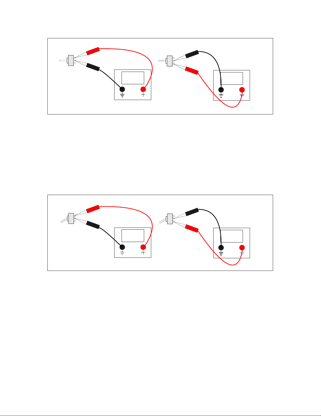
-----
-----
Figure 3-2: SPDT ON-OFF-ON in the Center Position
Now, without moving the switch lever position, remove the DMM lead from the “lower”
terminal it’s connected to and move it to the “upper” terminal. Now the connection
between the “upper” terminal and the center terminal should be shorted, while the switch
lever is in the down position. If not, bad switch. Now move the lever to the center
position – you should now have an open between the upper terminal and the center
terminal. If not…you get the picture. Move the switch lever to the “Up” position, and
again, you should still have an open between the “upper” terminal and the center terminal
on the rear of the switch.
-----
0.00
Figure 3-3: SPDT ON-OFF-ON in the “Down” position
So, once you’ve determined you have a good set of the right switches for the gate bus,
group them all together and lay them aside. Let’s look at our one remaining “oddball”
toggle switch – the SPDT ON-ON switch used for the Invert B Switch.
“ON-ON” means that we have only two positions for this switch. So, if you have more
than two positions (all together now) – Wrong Switch. Physically, it looks the same as
the gate bus switches – there are three terminals on the back. Only, because this switch
only has two positions, there are only two ways it can be bad. Again, hold the switch as
you would imagine it mounted on the panel. Hook one DMM lead to the center pin, and
one to the “lower” terminal. Flip the switch in the “up” position. You should have
continuity between the center terminal of the switch and the lower terminal of the switch.
Up is down. Now, flip the switch to the “down” position. You should now have an open
12

between the center and “lower” terminals of the switch. Now remove the DMM lead
from the “lower” terminal of the switch and place it on the “upper” terminal of the
switch. With the lever in the down position, you should have a short between the “upper”
terminal and the center terminal. Now flip the switch lever to the “up” position; you
should now have an open between the “upper” and center terminals of the switch. Once
we’ve identified this switch and made sure it works, put it in its own little spot so you
don’t mix it in with the gate bus switches.
As for the LEDs, it’s a good idea to mount them all in one orientation – either cathode
“up” or anode “up”. This serves to make things uniform as far as not worrying which is
the cathode or anode as you wire the panel up, but also, more importantly, it makes it
easier to “strap” the common connections together in the next step of panel assembly. Of
course, you’d want to mount at least all of the programming pots with the same
orientation to make the strapping process easier as well.
So, be sure you know on your LEDs which lead is the anode and which is the cathode.
Generally, LEDs will have the longer lead as the anode and the shorter lead as the
cathode. The body of the LED will also give you a clue which is which – it will have a
“flat” side, which will signify that’s where the cathode is.
"Flat" Side
Anode
Cathode
Figure 3-4: The LED Illustrated
But, let’s be habitual and double-check to be sure. You’ll need a DMM with a diode test
function to figure this out. Connect the positive lead of your DMM to what you believe
to be the anode of the LED. Connect the ground lead of your DMM to your idea of
which lead is the cathode. A diode tester often will have enough current to slightly
illuminate the LED as well – in a low light situation, you will see that. If you are using
the recommended high efficiency, low current LEDs, there probably will be no doubt if
the thing lights up or not.
Now, if you don’t see any illumination, you may have the leads reversed, the diode tester
doesn’t have enough juice to slightly illuminate the LED or you have a bad LED. Switch
the DMM leads around to the opposite legs of the LED. If you didn’t have slight
illumination before, and you do now, then your LED is good. Your positive lead is now
connected to the Anode and your ground lead is connected to the cathode.
13

If there is no change in the reading either way you switch the leads around, either your
diode checker doesn’t have the juice to even slightly illuminate the LED, its battery is
low, or the LED is toast. Toss any bad item away and get a new one, or put in new
batteries, as the situation dictates.
If your diode check function just can’t even get a glimmer out of the LED, there is one
other method that you can use to test your LEDs. If you have a breadboard, you can
mount the LED on the breadboard, use a 6K8 current limiting resistor (the standard Klee
value) and apply either 15V or 12V, depending on what power supply you intend to use.
Figure 3-5: An LED Test
Now, first of all, note the value of the 6K8 current limiting resistor. You may think that
is a pretty high value for an LED. In practice, many standard LEDs actually attain a very
respectable brightness with that value. The recommended high efficiency LEDs certainly
perform very well, also. If you should decide that you think the value is too high, and
you decide you’re going to lower it to get a really, really bright display, then that would
be a bad decision in this case. The health and longevity of your electro-music Klee
sequencer is dependent on this value. In other words, don’t do it. If you have any doubt,
breadboard it, and you will find the brightness is quite enough.
In the case of 12V operation, it may be permissible to lower the value to 4K7, but only in
the instance of 12V operation. However, try the 6K8 – you’ll find it performs well,
especially with a high efficiency, low current LED.
One more set of components deserves our pre-mount-the-panel-frenzy attention here: the
jacks. You should be sure which lugs of your jacks are which. The position of these lugs
can vary from manufacturer to manufacturer, so let’s be sure we know which are which.
14

If you’re using banana jacks, this is one of the benefits and luxuries of your jack of
choice – a banana jack has only one connection, so that leaves little up to chance. But
1/4” and 3.5mm jack users must keep track which lug is the ground and which lug is the
“tip”.
Tip Ground
Insulator
Figure 3-6: A 1/4” or 3.5 mm Cable Plug
Mono 3.5 mm and 1/4” plugs have two sections – the “tip” and ground connections. The
“tip” provides the signal, and the ground provides the ground connection that mates the
ground of your “send” device and your “receive” device. These two sections are
separated by a non-conducting ring on the plug.
When you plug one of these plugs into a jack, the jack will provide the signal output on
the “tip” lug of the jack and the ground reference on the ground lug of the jack.
So, to check which lug is which, plug a cable into your jack. Now, connect one lead of
your DMM/continuity tester to the tip of your cable and probe one lug of the jack. If the
lug you’re probing gives a near zero ohm reading (or your continuity tester squawks in
your ear) that is the “tip” lug. If the reading is open, move on to the next lug – if that one
gives low ohms/beeps, then that is the “tip” lug.
“Now….wait a minute.”, you might think, “Why don’t you just assume the other lug is
the “tip” lug if the current lug is not?”
15

Ground
Lug
Tip
Lug
0.00
Figure 3-7: Locating the Tip Lug
Because many of these jacks will have three (or more!) lugs, depending on the type you
purchased. Particularly, if it’s got three lugs, we’ll discuss that here in a second.
Now that you know which lug is the “tip” lug, write it down in a little diagram for
yourself. Move the DMM lead from the “tip” of the cable that’s still plugged into your
jack to the ground of the cable that’s plugged into your jack. Repeat the process until
you’re sure which lug is the ground lug of your jack.
Ground
Lug
Tip
Lug
0.00
Figure 3-8: Locating the Ground Lug
Back to that “third” lug: One option of the electro-music Klee Sequencer, called the
“Auto Switching External/Internal Range Option” (number 3 on page 9 of the front
panel/interconnect schematic) requires a normally closed (n.c.) switching jack. This type
of jack provides an extra lug called the “n.c. switch lug” that has continuity between the
16

“tip” lug only when a plug is not plugged into the jack. You know which lug is your
“tip” lug, so connect one lead of your DMM to that, and connect the other lead to the
“third” lug. If your cable is not plugged into the jack, you should read zero ohms (have
continuity) between these two lugs.
Ground
Lug
Tip
Lug
0.00
n.c.
Switch
Lug
Figure 3-9: No Cable Attached – N.C. Lug Closed
Now plug your cable into the jack. You should now read “open” between these two lugs.
If that’s the case, congratulations, you’ve just located the “n.c. switch” lug. If not, and
there are other lugs, check those. If you don’t find such a lug, then your jack will not
work with that option.
Ground
Lug
Tip
Lug
-------
n.c.
Switch
Lug
Figure 3-10: Cable Inserted – N.C. Lug Open
Now comes the time to mount the components! Keep a few things in mind – you
probably want to mount the hardy components first – the jacks, switches and pots. Then
you’ll probably want to attach and align your knobs and (if you’re really into this kind of
stuff) those cool little colored sleeves that fit over toggle switch levers. After that, you’ll
want to go back and put in your LEDs, using the mounting of your choice (which usually
involves an LED holder, or, in the case of those who’ve developed a well established
chrome fetish, chrome LED holders). Use the following tables to ensure that the right
components are mounted in the right places.
17

Table 3-2: Panel Mount Potentiometer List
Label Panel Des
(300 Series) Type
Programming Pot 1 R1 50K Linear Panel Mount Pot
Programming Pot 2 R2 50K Linear Panel Mount Pot
Programming Pot 3 R3 50K Linear Panel Mount Pot
Programming Pot 4 R4 50K Linear Panel Mount Pot
Programming Pot 5 R5 50K Linear Panel Mount Pot
Programming Pot 6 R6 50K Linear Panel Mount Pot
Programming Pot 7 R7 50K Linear Panel Mount Pot
Programming Pot 8 R8 50K Linear Panel Mount Pot
Programming Pot 9 R9 50K Linear Panel Mount Pot
Programming Pot 10 R10 50K Linear Panel Mount Pot
Programming Pot 11 R11 50K Linear Panel Mount Pot
Programming Pot 12 R12 50K Linear Panel Mount Pot
Programming Pot 13 R13 50K Linear Panel Mount Pot
Programming Pot 14 R14 50K Linear Panel Mount Pot
Programming Pot 15 R15 50K Linear Panel Mount Pot
Programming Pot 16 R16 50K Linear Panel Mount Pot
Glide A R20 1M Linear Panel Mount Pot
Glide B R21 1M Linear Panel Mount Pot
Glide A+B R19 1M Linear Panel Mount Pot
Random Level R18 100K Linear Panel Mount Pot
Random Reference R17 100K Linear Panel Mount Pot
Optional Variable Range R22 100K Linear Panel Mount Pot
Table 3-3: Panel Mount Toggle Switches
Label Panel Des
(300 Series) Type
Pattern Switch 1 SW1 SPST ON-OFF
Pattern Switch 2 SW2 SPST ON-OFF
Pattern Switch 3 SW3 SPST ON-OFF
Pattern Switch 4 SW4 SPST ON-OFF
Pattern Switch 5 SW5 SPST ON-OFF
Pattern Switch 6 SW6 SPST ON-OFF
Pattern Switch 7 SW7 SPST ON-OFF
Pattern Switch 8 SW8 SPST ON-OFF
Pattern Switch 9 SW9 SPST ON-OFF
Pattern Switch 10 SW10 SPST ON-OFF
Pattern Switch 11 SW11 SPST ON-OFF
Pattern Switch 12 SW12 SPST ON-OFF
Pattern Switch 13 SW13 SPST ON-OFF
Pattern Switch 14 SW14 SPST ON-OFF
18
Table of contents


