Electro-Voice VARIPLEX-B User manual

Description
The Electro-Voice VariplexTM-B is designed
specifically for use in ultrahigh-fidelity
cinema applications. The system offers
Electro-Voice patented technology. The
VariplexTM-B is a three-way configuration
that addresses many performance issues not
addressed in other three-way designs. The
VariplexTM-B employs Electro-Voice’s pat-
ented1Vari Intense®(VI) variable-intensity
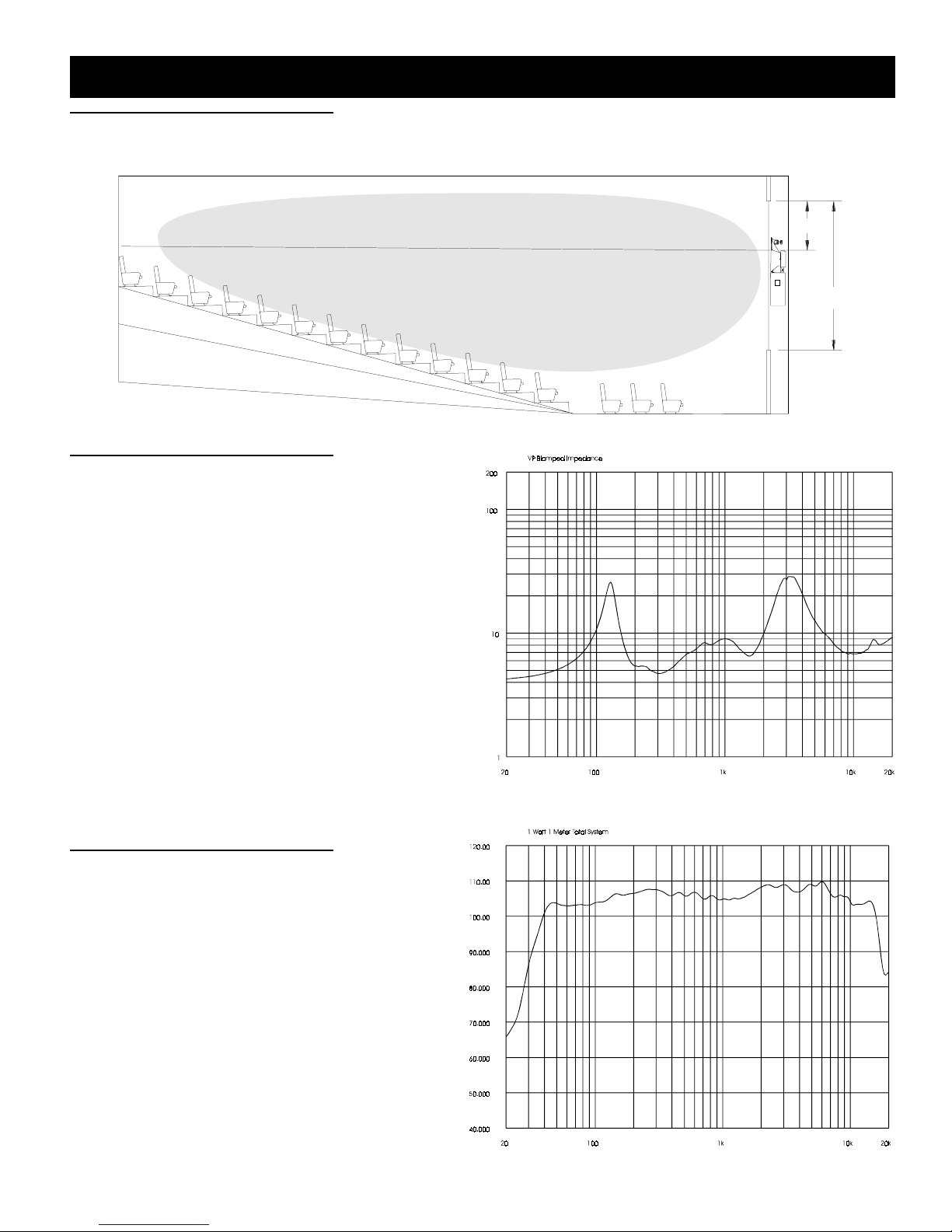
horn system. This design offers two funda-
mental advantages. The variable horn throat
impedance provides uniform sound pressure
levels over the entire auditorium. Conven-
tional horn systems attempt to do the same
by aiming the center of the high-frequency/
mid-frequency horn toward the rear of the
room. This conventional approach wastes
fully one-half of the system energy and head-
room, and radiates wasted energy onto the
ceiling and walls, thus producing reflections
that further degrade overall intelligibility and
system clarity. The patented variable- inten-
sity approach, on the other hand, compen-
sates for the natural phenomenon of sound
reduction with distance and produces
extremely uniform coverage for the entire
seating area. The same level of fidelity in
the front, middle and the back of the room is
achieved while substantially reducing
reflected energy and consequently greatly
improving tonal quality and intelligibility.
The advantages are twice the headroom and
greatly improved fidelity.
The VariplexTM-B is also unique in that its
three-way design utilizes a bass/mid-bass/
high-frequency approach rather than a con-
ventional bass mid-range/high-frequency
design. This mid-bass/high-frequency ap-
proach produces superior vocal clarity. Also
incorporated into the VariplexTM-B is
Electro-Voice’s Ring-Mode Decoupling
(RMDTM). Ring-Mode Decoupling employs
mechanical and acoustical equalization to
resolve system resonances (or ringing
modes) and frees electrical equalizers to per-
form the job they were originally intended
to perform, that being room equalization and
correction of the spectral characteristics
inherent in the tranducers themselves. Prior
designs have frequently attempted to "re-
solve” loudspeaker design issues with elec-
trical equalizers. RMDTM substantially im-
proves system transient detail and further
refines system clarity.
______________________
1 U.S. Patent 5,020,630, Loudspeakers & Horn Therefor.
VARIPLEXTM-B
Three-Way Screen System
•Vari-Intense®Technology for
smooth, even coverage
•Passive mid/high design allows
for biamped operation
•Compact design for limited
behind-the-screen space
•Ring-Mode Decoupling (RMDTM)
provides greater Intelligibility
•Digital Dynamics CapableTM
•Factory pre-assembled mid/
high unit
The compact design of the VariplexTM-Ballows
the system to be used even when behind-the-
screen space is limited. Compact design can
also provide a cost savings by allowing the
addition of extra seating.
The unique performance enhancements and
system capabilities are ideally suited to the
high dynamic-range demands of digital ma-
terial. When the VariplexTM-B is used in con-
junction with Electro-Voice’s subwoofers, the
combination defines a new standard for
realism and total system accuracy.
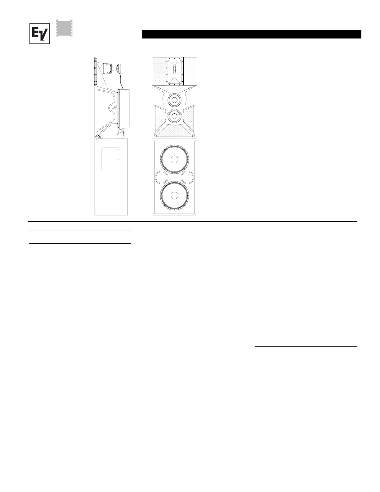
Mounting Instructions
Refer to Figures l and 2 for the following
steps.
1. Remove five screws on top of the
TL606DMT (see figure 2), the two far-
thest from the front of the enclosure are 1
3/4" and will be needed be replaced in
the same holes.
2. Set the mid/high subassembly on top of
the TL606DMT align the empty holes on
the TL606DMT with the three slots and
center pivot hole of the mid/high subas-
sembly mounting board. Reinstall the
screws previously removed, being sure
to install the longer two screws in the
R
Cinema
Systems

VARIPLEXTM-B
VARIPLEX
TM
-B
2
back slot under the adjustment bracket.
3. Adjust the horizontal position and se-
curely tighten all the bolts so that the mid/
high subassembly can not inadvertently
rotate.
4. Now loosen the two vertical adjustment
bolts just enough so the adjustment
guides will slide within the adjustment
slot. Adjust the vertical angle, by tilting
the mid/high subassembly, which will
slide the adjustment bolts along the slot
as shown in figure 1.
Figure 1— Mounting the
HPK-VariplexTM-B (pre-assembled mid/
high unit)
5. The aiming point of the mid/high subas-
sembly horn separates the mid-frequency
section from the high-frequency section,
(see figure 1). For proper imaging, this
point should be positioned just above the
vertical center line of the screen (typi-
cally 0.6 of the overall screen height),
(see figure 2). Then tilt vertically to align
with the head of the person in the last
seat of the theater, (See figure 2), and
tighten the vertical adjustment bolts, so
the mid/high subassembly can not inad-
vertently tilt backwards.
Frequency Response
Figure 4 shows the VariplexTM-B frequency
response with a swept sine-wave signal,
4 volts at 500 Hz, in an anechoic (echo free)
environment. The microphone was at a dis-
tance of 3.0 m (10 ft), on an axis with the aim-
ing point of the mid/high-frequency unit.
Aiming
Point
Use longer bolts
in back slot when
mounting the
HPK-Variplex-BFront of TL606DMT
Bolt Layout for the TL606DMT
Remove Only These Bolts
Back Edge of the Mid/High
sub-assembly Baseboard
(HPK-Variplex-B)
Pivot Point
Loosen for
vertical
adjustment
Loosen for horizontal
adjustment

VARIPLEX
TM
-B
VARIPLEXTM-B
3
Figure 4—VariplexTM-B Typical System
Frequency Response with DX34A LF/MF
Presets and MF/HF crossover unit:
Swept sine-wave input, under Anechoic
Environment, (normalized response,
from 4 volts at 500 Hz at 10 feet, with the
Microphone Axis Coincident with the
Aiming Point (midway between mid-
frequency horn and high-frequency
horn.)
Figure 2—Aiming the VariplexTM-B
Figure 3—VariplexTM-B Typical System
Impedance Response of the Mid and
High-Frequency Unit
Decibels (dB)
Frequency
Decibels (dB)
Frequency
8.0’
20.0’

VARIPLEXTM-B
VARIPLEX
TM
-B
4
CINEMA-Speaker Systems Part Number 535218 — 9829
600 Cecil Street, Buchanan, MI 49107
800/234-6831, 616/695-6831, 616/695-1304 Fax
©Telex Communications 1998 • Litho in U.S.A.
Uniform Limited Warranty Statement
Electro-Voice products are guaranteed
against malfunction due to defects in mate-
rials or workmanship for a specified period,
as noted in the individual product-line
statement(s) below, or in the individual prod-
uct data sheet or owner’s manual, beginning
with the date of original purchase. If such
malfunction occurs during the specified pe-
riod, the product will be repaired or replaced
(at our option) without charge. The product
will be returned to the customer prepaid.
Exclusions and Limitations: The Limited
Warranty does not apply to: (a) exterior fin-
ish or appearance; (b) certain specific items
described in the individual product-line
Specifications
Frequency response (See Figure 4):
40 Hz - 20,000 Hz
Power Handling,
Low Frequency:
800 watts continuous
(3,200 watts peak)
Mid Bass:
300 watts continuous
(1,200 watts peak)
High Frequency:
60 watts continuous
(240 watts peak)
Nominal Directivity,
Horizontal:
90°
short axis/60° long axis
Vertical (from system's geometric
axis):
5oup at 6 dB/50odown at -18 dB
System Impedance:
Bass Unit:
4 ohms nominal
Mid/High Unit:
8 ohms nominal
Sound Pressure at 1 Watt, 1 Meter
Input (See Figure 4),
LF/MF/HF (45 Hz to 1,600
Hz, average):
105.8 dB
Depth:
(44.8 cm) 17.62 in.
Net Weight:
(49.0 kg) 108 lb
Shipping Weight:
(52.62 kg) 116 lb
Mid Bass/High Frequency Section,
Height:
(109 cm) 42.8 in.
Width:
(59.7 cm) 23.5 in.
Depth:
(46.7 cm) 18.37 in.
Weight:
(31.98 kg) 70.5 lb
Shipping Weight:
(40.8 kg) 90 lb
Total System Dimensions,
Height: (209 cm) 82.3 in.
Width: (59.7 cm) 23.5 in.
Depth: (46.7cm) 18.37 in.
Weight: (78.2 kg) 172.5 lb
Shipping Weight: (93.44 kg) 206 lb
statement(s) below, or in the individual prod-
uct data sheet or owner’s manual; (c)
malfunction resulting from use or operation
of the product other than as specified in the
product data sheet or owner’s manual; (d)
malfunction resulting from misuse or abuse
of the product; or (e) malfunction occurring
at any time after repairs have been made
to the product by anyone other than
Electro-Voice Service or any of its authorized
service representatives.
Obtaining Warranty Service: To obtain
warranty service, a customer must deliver the
product, prepaid, to Electro-Voice Service or
any of its authorized service representatives
together with proof purchase of the product
in the form of a bill of sale or receipted in-
voice. A list of authorized service represen-
tatives is available from Electro-Voice Ser-
vice at 600 Cecil Street, Buchanan, MI 49107
(800/234-6831 or FAX 616/695-4743).
Other Rights: This warranty gives you spe-
cific legal rights, and you may have other
rights which vary from state to state.
For warranty repair, service information, or
a listing of the repair facilities nearest you,
contact the service repair department at:
616/695-6831 or 800/685-2606.
For technical assistance, contact Technical
Support at 800/234-6831 or 616/695-6831,
M-F, 8:00 a.m.to 5:00p.m. Eastern time.
Specifications subject to change without
notice.
Crossover Frequencies:
LF/MF:
330 Hz (24-dB-per-octave
Linkwitz-Riley)
High-Pack Mounting Holes:
Five, 1/4-20 bolts, allowing for
smooth horizontal adjustment and
secure attachment of the pre-
assembled high-pack.
Material,
Low-Frequency Enclosure:
Black vinyl-clad particle
board
Mid/High Frequency Horn:
Black fiber glass with a
black vinyl dual 8-inch
speaker enclosure
Input Connectors:
#10 screw terminals for bass, mid bass
and high frequency
Dimensions and Weight,
Bass Section,
Height:
(100cm) 39.5 in
Width:
(57.2 cm) 22.5 in.
Other Electro-Voice Home Theater System manuals