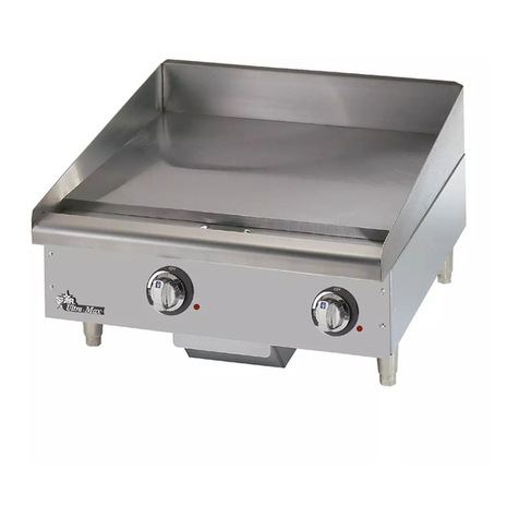
Electrolux Thermaline 9CHG584122 User manual

thermaline S90
FRY TOP GRILL/GRIDDLE, GAS
-
PLAQUE GRIL ET GRIDDLE, POUR GAZ
Doc.
62.9677.01_UL
Edition 1
05.2006
US INSTALLATION- AND OPERATING INSTRUCTIONS page 3
FR INSTRUCTIONS D’INSTALLATION ET D’EMPLOI page 13
FOR YOUR SAFETY
Do not store or use gasoline or
other flammable vapors or liquids
in the vicinity of this or any other
appliance.
POUR VOTRE SÉCURITÉ
Ne déposez pas ou n'employez
pas l'essence ou d'autres vapeurs
ou liquides inflammables à pro-
ximité de ceci ou d'aucun autre
appareil.
WARNING
Improper installation, adjust-
ment, alteration, service or
maintenance can cause property
damage, injury or death. Read the
installation, operating and
maintenance instructions thorou-
ghly before installing or servicing
this equipment.
AVERTISSEMENT
L'installation inexacte, l'ajuste-
ment, le changement, le service
ou l'entretien peuvent causer des
blessures matériels, des domma-
ges ou la mort. Lisez les instruc-
tions d'installation, d'opération et
d'entretien complètement avant
d'installer ou entretenir cet
équipement.
INSTRUCTION
Post in a prominent location instructions to be followed if the user smells gas. Consult
the local gas supplier to obtain the information.
Présentez dans des instructions en avant d'un endroit d'être suivi si l'utilisateur sent le
gaz. Consultez le fournisseur local de gaz pour obtenir l'information.

Doc. 62.9677.01_UL
Against wall - contre une paroi
Free standing - isolé
Connections - Raccordement
Gas - Gaz
Fig.1 INSTALLATION DRAWINGS - PLANS D'INSTALLATION

62.9677.01_UL Page 1
CONTENTS
I. GENERAL INFORMATION................................................................................................. 3
II. INSTALLATION INSTRUCTIONS....................................................................................... 5
III. OPERATING INSTRUCTIONS............................................................................................ 9
SOMMAIRE
IV. INSTRUCTIONS GÉNÉRALES......................................................................................... 13
V. INSTRUCTIONS RELATIVES À L'INSTALLATION......................................................... 15
VI. INSTRUCTIONS DE FONCTIONNEMENT....................................................................... 19
APPENDIX
VII. Nozzle Table - Tableau de gigleur

Page 2 62.9677.01_UL

GENERAL INFORMATION
62.9677.01_UL Seite 3
I . GENERAL INFORMATION
1. INSTRUCTIONS FOR SAFETY AND USE
1.1 INSTALLATION AND INITIAL OPERATION
1.2 OPERATOR'S OBLIGATIONS
1.3 USE AS PRESCRIBED
1.4 SAFETY-CONSCIOUS WORKING
1.5 AFTER-SALES SERVICE AND REPAIR
SThe installation, adjustment and initial opera-
tion of the appliance must be carried out
according to the manufacturer's instructions
and may only be done by an authorised spe-
cialist.
SInstallations for the supply of electricity and
gas must be carried out by approved special-
ists in compliance with specific national and
local regulations. They bear the responsibil-
ity.
SThe installation must conform with local
codes, or in the absence of local codes, with
the National Fuel Gas Code, ANSI
Z223.1/NFPA 54, or the Natural Gas and
Propane Installation Code, CSA B1 49.1.
SThe appliance and its individual shutoff valve
must be disconnected from the gas supply
piping system during any pressure testing of
that system at pressures in excess of 1/2 psi
(3.5 kPA)
SThe appliance must be isolated from the gas
supply piping system by closing its individual
manual shutoff valve during any pressure
testing of the gas supply piiping system at
test pressures equal to or less than 1/2 psi
(3.5 kPA)
SThe appliance must not be placed in
operation until the user has become familiar
with its operation. The operating instructions
and the related safety precautions must be
followed precisely. Follow strictly the
attention and warning label indications on the
appliances.
SThe manager is responsible for ensuring that
all components relevant to safety are in per-
fect working order at all times. The operating
condition of these components must be
examined by an authorised specialist at least
once a year and any defects remedied if
required.
SThe operator of this appliance is responsible
for total observation of the national regula-
tions concerning operating safety.
SRemain the manual for future reference.
SClosed containers (jars, cans, bottles, tubes,
etc.) must not be heated owing to the danger
of bursting and injuries.
SThe appliance is only approved for cooking
food in commercial establishments. .
S
Touching the hot cooking zones can cause
burns.
SWhen putting oil, fat, water or ingredients in
the preheated hot frying pan, they may spit -
danger of burning!
S
Overheated oil can ignite spontaneously. Never
use water to extinguish burning oil, but smother
the flames with the lid or a damp cloth.
SFilling quantity and temperature must be sel-
ected as appropriate. At high temperatures
(above 100°C) too much liquid in the trough
can lead to boiling over and spitting. - Dan-
ger of burning!
SThe escape of burnable gases represents a
fire and explosion hazard. Action in the case
of a gas leak and a smell of gas:
- No smoking, no fire
- Do not operate electric switches or bells.
- Do not operate the piezo igniter
- Close gas cylinder valves and the main
gas valve on the appliance.
- Ventilate the room thoroughly
- Place the leaking gas cylinders upright in
the open with valves closed.
SThe waste-gas outlets of the fryer become
hot. Avoid touching them.
SThe waste-gas outlets of the fryer are not to
be covered by any objects.
SSpraying the appliance or parts of it with a
high-pressure cleaning device may cause
malfunctions and is not to be done.
SKeep the appliance area free and clear from
combustibles
SDo not obstruct the flow of combustion and
ventilation air.
STo avoid damage to the appliance, do not let
water flow from the mixer tap onto the coo-
king plates.
SFor appliances with a downpipe, the hose
should lead into a drain opening which is cov-
ered by a grating such that it cannot be
kicked or tipped, or a drain gutter should run
underneath the appliance.
SDevices on wheels set up in block configura-
tion must be checked before each start-up
whether the potential equalization is con-
nected with the neighbour equipment. The
connection may be done only by authorized
technical personnel.
SAppliances on wheels must be fastened to
the building.
SIn the event of a permanent fault which inter-
feres with operation, the appliance must be
switched off and disconnected from the
power supply.
STo perform maintenance and repairs contact
the factory, the factory representative or a
local service company.
SRepair, maintenance work and other adjust-
ments are only to be carried out by an
authorised specialist. The valid local and
national regulations must be observed. This
applies especially to burners, ignition, safety
and control elements. Parts requiring
replacement are only to be replaced by origi-
nal spare parts. Periodic tests for gas leaks
must be carried out. A service contract is
therefore recommended.
SCleaning and maintenance must be done
only when the heating surfaces are cold. Do
not use inflammable liquids to clean the
appliance.
SAn obligatory service check is required
annually.
GENERAL INFORMATION
Seite 4 62.9677.01_UL
2. TECHNICAL DATA
9CHG584122
9CHG584123
9CHG584124
9CHG584125
3. PACKAGING
All the packaging materials used are environmentally friendly.
They may burnt at an incineration plant or sent for recycling.
4. TESTS / CERTIFICATES
All gas appliances are tested according to the standard ANSI
Z83.11-2002 and CSA 1.8-2002 of Gas Food Service Equip-
ment.
5. SPECIFICATION PLATE
The specification plate (E) is located in each case inside and
outside on the right of the operator panel (C) (Seite 6 Fig. 5).
The serial number is marked on the type plate. The 8 digits
give following information:
Y last digit of the year of production
WW week of production
XXXXX running number
PNC Appli-
ances Appliance type
Width
Depth
Height
Frying
surface Power
Gas rating
inch
mm
WHGURFOOOO
31.5
35.4
35.4
800
900
900
29.4“ x
25.6“
(748 x
649mm)
17.4 kW
59000 BTU
WHGUSFOOOO
WHGURAOOOO
WHGUSAOOOO

INSTALLATION INSTRUCTIONS
62.9677.01_UL Seite 5
II . INSTALLATION INSTRUCTIONS
1. INSTALLATION
The appliance is designed for connection to fixed lines. The
appliances are suitable for setting up as single appliances or as
a group of appliances. They can be set up freely in the room,
side by side, at the side and/or at the back against a wall.
Gaps between two appliances or appliance and sidewall
should be filled with a FDA approved silicone such as Samco
RTV103.
1.1 DISTANCES
If an appliance is set up next to or against temperature-sensi-
tive furniture or similar, a safety gap of approximately 6“ (150
mm) should be maintained or some form of heat insulation fit-
ted.
The walls must be made up of non-combustible material like
tiles or steel.
1.2 HEIGHT ADJUSTMENT
Appliance on feet.
DTurn the lower part of the feed to adjust the appliance high.
The feet are adjustable from 4“ to 8“ (100 to 200 mm). A high
of 8“ (200 mm) can be recommended and results in an appli-
ance high of 35,4“ (900 mm).
Note:
Adjustment of the legs shall provide an unobstructed
clearance of minimal 6“ (150 mm) and maximal 8“ (200
mm) beneath the unit due to sanitary and stability
aspects.
The lower part of the foot must not be unscrewed too far.
The exposure of threads is prohibited.
1.3 ASSEMBLING TWO APPLIANCES
The assembly kit contains two of each of the following:
caged nuts (1 / Fig.1) pre-assembled on the right-hand side of
the appliance, hexagonal screws M8x25 (1 / Fig.1) and moun-
ting links (2 / Fig.1)
DRemove the control panels from both appliances as in 2.2
DRemove the front panels from both appliances as in 2.1
DKeeping the screw (1 / Fig.1) loose, turn it until it is approxi-
mately 5 mm deep in the caged nut.
Positioning the appliances:
DPlace the appliances next to one other.
DAlign for position and height.
Connect the appliances:
DFit the mounting link (2 / Fig.1) into the inside of the second
appliance's left connecting plate.
DTighten the screws.
Note
If required, the caged nuts can also be fitted on the other side
of the appliance.
Appliance on feet: Alignment is carried out by screwing the
lower foot parts in or out.
Appliance on
steel plinth: Irregularities or differences in height can
be equalized by inserting one or several
strips of chrome nickel steel.
a
b
c
Fig.1 Lateral connection
(1) (1)
(2)
(2)
(3b)
(3a)
(3c)
(1)
(2)
1(3c)

INSTALLATION INSTRUCTIONS
Seite 6 62.9677.01_UL
1.4 SIDEWALL (D)
The assembly kit contains two of each of the following:
hexagonal screws M8x25 (1 / Fig.1), bolts with retaining rings
(2 / Fig.1), mounting links (3 / Fig.1), hexagonal screws M8x16
with serrated washers and hexagonal nuts M8, hexagonal
screws M5 with serrated washers (4 / Fig.2)
and a fastening angle (5 / Fig.2).
DInsert the bolts with the retaining rings (2 / Fig.1a) from out-
side into the guide in the sidewall.
DKeeping the screw (1 / Fig.1a) loose, turn it until it is
approximately 5 mm deep in the pre-assembled caged
nuts in the sidewall.
DAttach the fastening angle (5 / Fig.2b) to the bottom of the
frame using the screws, serrated washers and nuts.
D(4 / Fig.2).
DPosition the sidewall and screw it on from below using two
hexagonal screws and the serrated washers.
DFit the mounting link (3 / Fig.1b) into the inside of the appli-
ance's connecting plate.
DAlign the sidewall and firmly tighten all screws.
1.5 STEEL PLINTH
To assemble the plinth you will need:
• Right and left side plinth (1 / Fig.3).
• Plinth for the front and, for free-standing appliances, for the
rear also (2 / Fig.3).
DPush the side plinth (1 / Fig.3) onto the legs from front to
rear using the fastener. The larger gap (b / Fig.3) on the
fastener must be at the bottom.
DAffix the fasteners (3 / Fig.3) to the plinth (2 / Fig.3).
DThe larger gap (b / Fig.3) on the fastener must be at the
bottom.
DAttach the plinth with the fasteners (3 / Fig.3) onto the feet.
1.6 ASSEMBLING ON CASTORS
The assembly kit for mounting on castors contains two cross
bars (2/Fig.4a) each with a fixed rear wheel (1/Fig.4a) and a
turnable front wheel (3/Fig.4a).
Mounting the castors:
DPut the appliance on supports.
DRemove the feet; each is tightened with four screws
(Fig.4b).
DBring the two cross bars into the correct position below the
appliance and fasten it with 8 screws arrows (Fig.4a).
DRemove the supports.
DFasten the appliance to the building. Use the hole to attach
a chain descending from the wall (arrow/Fig.4c). Making
sure the chain is shorter than the gas and electric connec-
tions.
Note:
Appliances on wheels must be secured by fasten it to the
building.
2. ACCESS TO INTERIOR
Note:
Only authorized technicians may access the interior.
a
b
Fig.2 Assemblage of sidewall
a
b
Fig. 3 Plinth assembly
1
()
(5) (4)
1(3c)
1
()
(5) (4)
(1)
(2)
(3)
b
b
1(3c)
(1)
(2)
(3)
a
bc
Fig.4 Assemblage on castors
Fig. 5 General view
1
()
(5) (4)
1(3c) 1(3c)
1
3
13
D
D
B
EC
11

INSTALLATION INSTRUCTIONS
62.9677.01_UL Seite 7
2.1 FRONT PANELS (A) and (B)
DUnscrew screws (1 or 3). Also, in the case of a built-in oven,
unscrew screws (2 and/or 4) on the inside of the oven.
DPull the panel away forwards and downwards.
2.2 CONTROL PANEL (C)
DRemove the knob.
DLoosen the screws underneath (1 / Fig.7a) and remove the
base plate.
DLoosen the screws (2 / Fig.7b) and 3 / Fig.7c)
DRemove the panel.
2.3 OVEN, STORAGE SPACE, HOT CABINET
DRemove panels A, B and C.
DUndo screws (5).
DPull out element.
3. DOWNPIPE
Work surfaces with a downpipe (Fig.8a) have the downpipe
opening on the right-hand side of the appliance. A flexible sili-
con hose when installed in the standard manner ends under-
neath and to the right, 0.8“ (20 mm) behind the front of the
appliance (Fig.8b).
DAlternatively, the hose can be relocated to the rear and be
routed through other pre-cut openings (Fig.8c).
Fig.6 Front panel
ab
Fig. 7 Control panel
c
(1)
1(3c)
(1) 1(3c)
(2)
(3)
ab
Fig. 8 Downpipe
c
1(3c)
(1)
(3)

INSTALLATION INSTRUCTIONS
Seite 8 62.9677.01_UL
4. GAS CONNECTION
The installation of the gas connection, as well as the laying of
the customer's gas line, is only to be carried out by an author-
ised specialist subject to the relevant national and local regula-
tions.
NOTE
• The gas appliance may only be installed in an adequately
ventilated location.
• Appliances are set up for natural gas. The type of gas, gas
pressure and gas category are entered on the specification
plate. Prior to connection, check that the appliance is set
up for the type of gas available on site. To do this, compare
the details on the specification plate with the existing gas
data.
• If this is not the case, the appliance must be converted or
adapted by the service personnel responsible to suit local
conditions. The following points should be noted:
- Has the appliance been tested for the new gas data?
- Conversion in accordance with the Service Manual.
- A new specification plate or a durable marking with the
new gas data must be affixed to the appliance.
4.1 CONNECTION
Gas-only appliances as well as combination electric and gas
appliances require a gas connection.
The gas connection is located under the appliance on the right
hand side. For all types the gas connection is NPT 3/4“.
The installation of a dirt trap in the gas supply line by the owner
is recommended.
After connection, all lines carrying gas must be tested for leaks
at operating pressure by painting with non-corrosive foam-
forming media, (e.g. soapy water or leak spray).
4.2 GAS PRESSURE
The current gas pressure should be measured at the Mertik
regulator with a liquid U-tube manometer (scale at least 0.1
mbar = 1 mm water column).
DRemove the control panel. The measuring nipple is located
in downwards direction at the gas supply pipe before the
two gas valves.
DClose off the mains gas leading to the appliance.
DThe measuring nipple is provided at the left side of the reg-
ulator. The incoming pressure is measured in front, the out-
going pressure behind.
DLoosen the slotted screw (1 turn) in the measuring nipple.
Then connect the pressure gauge by attaching a flexible
tube to the nipple (out-side diameter 8 mm).
DOpen the main gas leading to the appliance.
DRun all burners on the appliance at full output.
DCheck whether the connection pressure is in permitted tol-
erance.
DTurn off the appliance again.
DClose the main gas valve.
DRetighten the slotted screw in the measuring nipple. Gas
pressure deviation tolerances are laid down by EN 203. If
the existing gas pressure is outside the given tolerances,
correct combustion can no longer be ensured. Compulsory
measures: pressure adjustment by the gas works or con-
version of the range by the service personnel. Please refer
to "Conversion to another gas type".
Gas pressure tolerances
Gas pressure variation tolerances are as
follows: mbar
Gas type Normal
pressure Min.
pressure
inch
water g. mbar inch
water g. mbar
Natural gas A 7 17.4 3.5 8.7
USA
Liquid gas E 11 27.4 8.0 20
Propane
USA

OPERATING INSTRUCTIONS
62.9677.01_UL Seite 9
III . OPERATING INSTRUCTIONS
1. GENERAL
The appliance is used for frying various types of meat, sausa-
ges, fish and vegetables on a gas-heated steel plate.
Optionally the appliance is equipped with a smooth griddle
plate or a combined grill/griddle plate with 1/3 grooved and 2/3
smooth surface.
Plate temperature control is stepless and separate for the left
and right halves of the plate.
A drawer (GN container 2/8) in the open storage space in the
base serves as a drip pan for draining liquids.
Additional equipment:
- GN container 1/1, 2/1,
- Scraper grill/griddle.
2. OPERATION
DFor liquid gas operation also open the bottle or tank valve.
DSwitch on gas burner (Chapters 2.1 and 2.2):
2.1 IGNITING THE PILOT BURNER
The left and right plate halves are operated separately, each
by a rotary knob (1 / Fig.9) and a Piezo switch.
DPress in the knob (2/Fig.9) of the piezo igniter and turn it
clockwise to the stop.
DHold the knob (2/Fig.9) pushed in for a few seconds.
DWhile still pressing, turn it to the left. The gas escaping at
the pilot burner will be ignited.
DAfter lighting the pilot flame, keep the rotary switch pushed
in for about 10 seconds more.
DIf the pilot light goes out again, repeat the whole process.
2.2 IGNITING THE MAIN BURNER
DTurn the knob (1/Fig.9) anti-clockwise from position 1 pilot
burner ignition to the desired setting.
DSetting 7 equates to the maximum burner output or rated
thermal load.
2.3 TEMPERATURE SELECTION
With the knob (1/Fig.9) the temperature can be steplessly
adjusted between 195 and 570°F (90 and 300°C).
The intensity of the flame can be adjusted between the highest
setting 7 and the lowest setting 1.
2.4 INITIAL OPERATION
Wash the whole plate with hot soapy water, rinse with clean
water and allow to dry. The new appliance should then be hea-
ted up for 30 minutes at a temperature of 320°F (160°C).
2.4.1 PREHEATING
DThe complete energy supply should be used for heating
up.
2.5 WORKING RULES
The temperature must be adapted to the food to be cooked:
• thin pieces require higher temperatures and shorter coo-
king times,
• thick pieces require lower temperatures and longer cooking
times.
Before starting to fry, moisten the plate lightly with oil so that
the food sticks less.
Each time after frying, the cooking residues must be removed
from the plate. This can be done with the scraper. If the frying
plate is not cleaned, the flow of heat into the food is reduced,
altering cooking time and quality.
2.5.1 Grill plate
The food rests only on the ridges of the grooves and gets a
dark striped pattern, or a diamond-shaped pattern by being tur-
ned. The flow of heat into the item being grilled comes mainly
from the ridges. Burnt stripes on the contact surface are a
result of excessive grilling time.
Thick pieces of meat and sausages cannot be properly grilled
with the grooved grill plate alone. To do this requires the com-
bination of grill and griddle plate.
2.5.2 Griddle plate
The full surface of the food is in contact and the heat is trans-
mitted intensively. Frying temperatures of 400 - 480°F (200 -
250°C) is no problem, even for thick pieces of meat and
sausages.
2.6 COLLECTING LIQUIDS
Draining cooking liquids can be collected in the base unit. A
drawer is provided for this purpose.
Note
DWhen draining oil, fat or water into the drip pan there may
be spitting - danger of burning!
1Knob
2 Piezo ignition
device
Fig.9 Operating panel
12

OPERATING INSTRUCTIONS
Seite 10 62.9677.01_UL
2.7 SWITCHING OFF THE GRILL/GRIDDLE
2.7.1 MAIN BURNER
DTurn the knob (1/Fig.9) back clockwise from highest setting
7 to pilot burner ignition 1.
The gas supply to the main burner is stopped and the main
flame is shut down. The flame of the pilot burner keeps on
burning and is available for further main burner ignitions.
2.7.2 PILOT BURNER FLAME
DPress the knob (2/Fig.9) lightly and turn clockwise from
pilot burner ignition to Off.
The complete gas supply is cut off and the pilot light
extinguishs.
= Off
DIgnition can only start again when the heating element has
cooled down.
2.7.3 LONG SHUT-DOWNS
The following should be observed when shutting down for a
long period:
DWhen operating with liquid gas, also turn off the bottle or
tank valve.
DNever store the fryer where the temperature can drop
below 32°F (0 °C).
DRub all chrome nickel steel surfaces with a cloth soaked in
vaseline oil, to lay down a thin protective coating.
DAir the installation site regularly.
3. CLEANING
The appliance should be cooled before every cleaning
operation.
DShut off all the gas taps and control valves on the range.
DUse a brush to wash the base plate with hot water to which
a fat-dissolving agent has been added, rinse with hot water
and rub dry. Do not use bleaching and chloric cleaning
agents.
DHeavy soiling can be removed with a scraper.
DDepending on utilization, the pressure tube and the drip
pan should be cleaned periodically with a small brush.
DWash rust-resistant chrome nickel steel panels with hot
soapy water to which a fat-dissolving agent has been
added and rub them dry.
Note
DThe appliance must not be sprayed with a water jet or high-
pressure cleaner.
DThe floor directly in front of, near and behind the appliance
must be cleaned normally without a high-pressure cleaner.
DNever use steel wool, spatulas or ordinary steel wire
brushes for cleaning the surfaces, since the deposition of
steel particles can lead to rust formation. Stainless steel
wool can possibly be used, but only in the grinding direc-
tion.
DNever use chloric products (bleaching dye, hydrogen chlo-
ride etc.) for cleaning chrome nickel steel, even if they are
diluted.
DNever use corrosive substances for cleaning the floor
under the appliance (e.g. hydrochloric acid). Clean the
appliance with commercial cleaning agents. Do not use
granular or abrasive agents.
3.1 GAS BURNER
So far as is necessary, the pilot burner and main burner are
cleaned by after-sales service.
3.2 FLAME
In a visual check, the flames must be dark blue without any
upper yellow or orange tips; they must be stable and soot-free
and adhere firmly to the outlets.
If there is a lack of primary air, the flame has yellow streaks
and tips; if there is too much primary air, the flame is short,
transparent and tends to lift off the burner.
When the flame is correctly adjusted, it must not lift off or back-
fire when the burner is cold as well as warm.
The flame will backfire into the inside of the burner when the
speed of the gas-air mixture through the burner outlets is too
low, particularly when the air passages are dirty.
The different ignition processes must also take place without
any delays. This concerns: ignition, arc-through and. extending
the flame over the whole burner area.
If the flame fails to meet all the requirements, cleaning or
maintenance is necessary.
4. MALFUNCTION
Plate does not heat up. • The thermal limiter has
tripped.
• Defective thermostat.
• The capillary tube sen-
sor is damaged.
- Inform After-sales ser-
vice.
Flame smokes. • Gas mix too rich.
• Partially blocked burner
gaps.
- Inform Customer Ser-
vice.
Long yellow flame tips. • Mixing tube narrowed by
dirt. - Inform Customer Ser-
vice.
Flame lifts off. • Exit velocity too high due
to blocked burner gaps.
• Pressure regulator on
gas cylinder not opera-
ting correctly.
- Inform Customer Ser-
vice.
Flame flashes back. • Mixture too lean.
• Insufficient exit velocity
at burner gaps.
• Soiled airways
• Blocked nozzle.
- Inform Customer Ser-
vice.
No flame or flame too
small. • Blocked nozzle or mixer
tube.
• Blocked gas tap.
•Nogas.
• Insufficient gas pres-
sure.
- Inform Customer Ser-
vice.
- Check gas tap setting.
No flame at low setting. • Blocked low setting
nozzle. - Inform Customer Ser-
vice.
No flame. • Blocked burner gaps.
• Blocked nozzle. - Clean pilot burner cap.
Flame goes out after con-
trol valve release. • Thermo-element insuf-
ficiently heated (dirty?)
• Defective thermo-ele-
ment
- Inform Customer Ser-
vice.
Flame too small or too
large. • Primary air ratio adju-
sted.
• Nozzle blocked.
- Inform Customer Ser-
vice.
Malfunction Possible cause Remedy
Pilot burner

OPERATING INSTRUCTIONS
62.9677.01_UL Seite 11
5. STORAGE SPACE
The storage space (Fig.10) is incorporated into the base unit.
Recommended accessories:
- Shelf holder (1) 2 off.
- Shelves (2) 1 off.
1 Shelf holder
2 Shelves
Fig.10 Storage space

OPERATING INSTRUCTIONS
Seite 12 62.9677.01_UL

INSTRUCTIONS GÉNÉRALES
62.9677.01_UL Page 13
I . INSTRUCTIONS GÉNÉRALES
1. CONSIGNES DE SÉCURITÉ ET D'UTILISATION
1.1 INSTALLATION ET MISE EN SERVICE
1.2 OBLIGATIONS DE L'UTILISATEUR
1.3 UTILISATION CORRECTE
1.4 TRAVAILLER EN TOUTE SÉCURITÉ
SLe montage, le réglage et la première mise
en service de l'appareil doivent s'effectuer
conformément aux instructions du fabricant
et être confiés exclusivement à un technicien
agréé.
SLes raccordements au réseau électrique et
de distribution du gaz doivent être réalisés
par du personnel agréé, dans le respect des
dispositions locales en vigueur dans le pays
d'installation. Celui-ci sera tenu pour respon-
sable en cas d'installation incorrecte.
SL'installation doit être conforme aux codes en
vigueur localement, ou, en l'absence de
ceux-ci, au code national du gaz combusti-
ble, ANSI Z223.1/NFPA 54, ou au code
d'installation du gaz naturel et du propane,
CSA B1 49.1.
SIl faut que l'appareil et la vanne d'arrêt
automatique relative soient déconnectés du
système de tuyauterie d'alimentation du gaz
lors de tout test de pression effectué sur ce
système à des pressions supérieures à 1/2
psi (3,5 kPA)
SL'appareil doit être isolé du système de
tuyauterie d'alimentation du gaz en fermant
manuellement la vanne d'arrêt automatique
lors de tout test de pression effectué sur ce
système à des pressions de test équiva-
lentes ou inférieures à 1/2 psi (3,5 kPA)
SL'utilisateur ne doit pas mettre l'appareil en
marche avant de s'être familiarisé avec son
fonctionnement. Il est impératif de suivre les
instructions et les consignes de sécurité
indiquées dans la Notice d'emploi. Respecter
rigoureusement les signaux d'avertissement
et de mise en garde appliqués sur les
appareils.
SIl incombe à l'utilisateur de garantir l'efficacité
permanente de toutes les pièces importantes
pour la sécurité de l'appareil. Il convient de
faire contrôler le bon fonctionnement de ces
pièces au moins une fois par an par un tech-
nicien agréé et de les remettre à neuf, si
nécessaire.
SL'utilisateur est pleinement tenu de se con-
former à la réglementation nationale en
matière de sécurité de fonctionnement de
ces appareils.
SLe mode d'emploi doit être conservé pour
toute consultation ultérieure.
SLes récipients hermétiques ne doivent pas
être chauffés sous peine de les faire exploser
et de provoquer des blessures.
SL'appareil ne doit en aucun cas être utilisé
pour frire des aliments.
SOn peut se brûler si l'on entre en contact
avec les plaques chaudes.
SSi vous remplissez une poêle préchauffée, et
donc très chaude, avec de l'huile, de la
graisse, de l'eau ou des aliments, ceux-ci
peuvent provoquer des éclaboussures - Dan-
ger de brûlures !
SL'huile, lorsqu'elle est surchauffée, peut
prendre feu. Ne jetez jamais d'eau sur de
l'huile en feu, mais éteignez les flammes en
posant le couvercle de l'ustensile de cuisson
ou à l'aide d'un linge mouillé.
SIl faut sélectionner la température et le
volume de remplissage. Si la température est
supérieure à 100°C, le liquide dans le bac
peut bouillir et déborder. - Danger ! Risque
de brûlures !
SLes fuites de gaz combustible sont source de
risque d'incendie et d'explosion. Comporte-
ment à adopter en cas de fuite ou d'émanati-
ons de gaz :
- Évitez de fumer et d'allumer du feu
- N'actionnez ni interrupteurs ni sonneries
électriques ni piezo
- N'actionnez pas piezo-allumeur
- Fermez les valves des bouteilles de gaz
et le robinet à gaz principal sur l'appareil
- Aérez soigneusement la pièce
- Transportez les bouteilles de gaz défec-
tueuses en plein air, fermez le robinet et
laissez-les en position verticale.
SLes orifices prévus pour les gaz d'échappe-
ment du four deviennent chauds lorsque le
four est en service ; évitez de les toucher.
SÉvitez d'obstruer les orifices prévus pour les
gaz d'échappement du four avec des objets.
SL'aspersion de l'appareil ou de ses éléments
à l'aide d'appareils de nettoyage sous
pression est à proscrire, car ceux-ci peuvent
engendrer des défauts de fonctionnement.
SNe rangez pas de matériaux combustibles à
proximité de l'appareil.
SVeillez à ce que l'évacuation des produits de
la combustion ne soit pas entravée et que les
bouches d'aération ne soient pas obstruées.
SSur les appareils équipés d'une sortie, il con-
vient soit de raccorder le flexible à l'orifice de
sortie muni d'une grille résistante avec cou-
vercle anti-usure et anti-basculement ou de
disposer une rigole de déversement au-des-
sous de l'appareil.
SLes appareils sur roues installés dans une
configuration multiple doivent être contrôlés
avant chaque démarrage si le conducteur
d'équipotentialité est reliée à l'installation du
voisin. La connexion doit exclusivement être
confiée à des techniciens agréés.
SLes appareils sur roues doivent être fixés au
mur.

INSTRUCTIONS GÉNÉRALES
Page 14 62.9677.01_UL
1.5 SERVICE-APRÈS-VENTE ET RÉPARATION
2. DONNÉES TECHNIQUES
9CHG584122
9CHG584123
9CHG584124
9CHG584125
3. EMBALLAGE
Tous les matériaux d'emballage utilisés sont non polluants.
Ils peuvent être brûlés dans une installation d'incinération ou
recyclés.
4. TESTS / CERTIFICATS
Tous les appareils à gaz sont testés conformément aux stand-
ard ANSI/NSF 4 - 2002, Commercial Cooking, Rethermaliza-
tion, and Powered Hot Food Holding and Transport Equipment
et ANSI Z83.11-2002 et CSA1.8-2002, Gas Food Service
Equipment.
5. PLAQUE SIGNALÉTIQUE
La plaque signalétique (E) figure à l'intérieur et à l'extérieur du
panneau de commandes (C), à droite (Page 16 Fig.5).
Le numéro à 8 chiffres de la plaque signalétique est composé
comme suit:
Y dernier chiffre de l'année de fabrication
WW semaine de fabrication
XXXXX numéro d'ordre
SSi un problème persistant empêche le
fonctionnement correct de l'appareil, mettez-
le hors tension et débranchez-le.
SPour toute opération d'entretien ou de répa-
ration, adressez-vous au fabricant, à un
représentant agréé ou au Service Après-
vente local.
SToute opération de réparation, d'entretien et
de réglage doit être effectuée par un techni-
cien agréé, en respectant les dispositions
locales en vigueur dans le pays d'installation.
Ceci concerne en particulier les dispositifs
des brûleurs, d'allumage, de sécurité et de
réglage. Les pièces défectueuses doivent
être remplacées par des pièces d'origine.
L'étanchéité du dispositif d'arrivée du gaz
doit faire l'objet de contrôles réguliers.
Par conséquent, il est recommandé de sti-
puler un contrat d'entretien pour votre
appareil.
SLes opérations de nettoyage et d'entretien de
votre appareil doivent s'effectuer lorsque les
surfaces chauffantes sont froides. N'utilisez
jamais de liquides inflammables pour net-
toyer votre appareil.
SL'appareil doit faire l'objet d'une révision
générale à une fréquence annuelle.
Appareil PNC Modèle de l'appareil Largeur
Profondeur
Hauteur
Superficie Puissance
Consommation
de gaz
inch
mm
WHGURFOOOO
31.5
35.4
35.4
800
900
900
29.4“ x
25.6“
(748 x
649mm)
17.4kW
59000 BTU
WHGUSFOOOO
WHGURAOOOO
WHGUSAOOOO

INSTRUCTIONS RELATIVES À L'INSTALLATION
62.9677.01_UL Page 15
II . INSTRUCTIONS RELATIVES À L'INSTALLATION
1. MISE EN PLACE
Cet appareil est conçu pour être raccordé à des conduites
fixes. Les appareils peuvent être montés individuellement ou
en groupe. Ils peuvent être installés de façon indépendante,
côte à côte, avec un côté et/ou la partie arrière de l'appareil
reposant contre une paroi.
Les interstices entre deux appareils ou entre un appareil et le
mur latéral doivent être comblés avec du silicone homologué
par le FDA tel que Samco RTV103.
1.1 DISTANCES
Si l'appareil doit être monté au-dessus ou à côté de meubles
sensibles à la température, il convient de prévoir un espace de
6“ (150 mm) environ entre l'appareil et le meuble ou d'appli-
quer un panneau d'isolation thermique.
Les parois doivent être fabriquées en un matériau non com-
bustible, tel que carreaux ou revêtement en acier.
1.2 RÉGLAGE DE LA HAUTEUR
Appareil sur des pieds.
DTournez la partie plus inférieure de l'alimentation pour aju-
ster la haute d'appareils.
L'alimentation sont réglable de 4“ à 8“ (100 à 200 mm). Une
haute de 8“ (200 mm) peut être recommandée et des résultats
dans une haute d'appareils de 35,4“ (900 mm).
Note :
L'ajustement des pieds fournira un dégagement dégagé
des 6“ (150 mm) minimaux et des 8“ (200 mm) maximaux
sous l'unité due aux aspects sanitaires et de stabilité.
La partie plus inférieure du pied ne doit pas être dévissée
trop loin. L'exposition des fils est interdite.
1.3 ASSEMBLAGE DE DEUX APPAREILS
Chaque kit d'assemblage comprend respectivement deux
écrous en cage (1 / Fig.1) pré-montés à l'avant droit de
l'appareil et des éclisses (2 / fig 1),
DRetirez les panneaux de commande des deux appareils
comme indiqué en 2.2
DRetirez les panneaux avant des deux appareils comme
indiqué en 2.1
DVissez la vis (1 /fig. 1) à env. 5 mm de profondeur dans
l'écrou en cage.
Positionnement des appareils :
DPlacez les deux appareils l'un à côté de l'autre.
DAjustez la position et la hauteur :
Assemblage des appareils :
DInsérez l'éclisse (2 / fig. 1) à l'intérieur sur la plaque
d'assemblage droite du deuxième appareil.
DSerrez fermement les vis.
N.B. :
Au besoin, les écrous en cage peuvent également être appli-
qués sur l'autre côté de l'appareil.
Le raccordement de deux appareils (fig. 1c, flèche) doit corre-
spondre aux règlements hygiéniques respectifs le standard
NSF/ANSI 4. Tout le résulter joint et des coutures dans une
zone exposée aux projections seront scellées et lisser.
Appareil muni
de pieds : Le réglage s'effectue en vissant ou en
dévissant la partie inférieure des pieds.
Appareil installé
sur un socle en
acier :
Si le sol présente des irrégularités ou des
dénivellations, corrigez celles-ci en plaçant
une ou plusieurs tôles en nichrome en des-
sous de l'appareil.
a
b
c
Fig.1 Raccordement latéral
(1) (1)
(2)
(2)
(3b)
(3a)
(3c)
(1)
(2)
1(3c)

INSTRUCTIONS RELATIVES À L'INSTALLATION
Page 16 62.9677.01_UL
1.4 PAROI LATERALE (D)
Chaque kit d'assemblage comprend respectivement deux
vis hexagonales M8 x 25 (1 / Fig.1), des boulons avec circlip (2
/ Fig.1), des éclisses (3 / Fig.1), des vis hexagonales M8 x 16
avec rondelles à denture intérieure et des vis hexagonales M8,
des vis hexagonales M5 avec rondelles à denture intérieure (4
/ Fig.1)
et une équerre de fixation (5 / Fig.2).
DInsérez les boulons avec circlip (2 / Fig.1a) depuis
l'extérieur dans l'orifice prévu à cet effet dans la paroi
latérale.
DVissez la vis (3 / Fig.1) à env. 5 mm de profondeur dans
l'écrou en cage pré-monté dans la paroi latérale.
DFixez l'équerre de fixation (5 / Fig.2b) à l'aide des vis, des
rondelles à denture intérieure et des écrous en bas du
châssis. (4 / Fig.2)
DPositionnez la paroi latérale et vissez le bas à l'aide des
deux vis hexagonales et des rondelles à denture intérieure.
DInsérez l'éclisse (3 / Fig.1a) à l'intérieur de l'appareil sur la
plaque d'assemblage.
DAjustez la paroi latérale et serrez toutes les vis.
1.5 SOCLE EN ACIER
Eléments requis pour le montage du socle :
• Socles latéraux droit et gauche (1 / Fig.3).
• Socle pour panneau avant et, pour les appareils autono-
mes, pour panneau arrière également (2 / Fig.3).
DPoussez les pieds du socle latéral (1 / Fig.3) d'avant en
arrière à l'aide de l'attache. L'intervalle le plus grand avec
l'attache (b / fig. 3) doit se situer en bas.
DPlacez les attaches (3 / fig. 3) sur le socle (2 / Fig.3).
DL'intervalle le plus grand avec l'attache (b / Fig.3) doit se
situer en bas.
DPlacez le socle sur les pieds à l'aide des attaches (3 /
Fig.3).
1.6 ASSEMBLAGE SUR ROULETTES
Le kit de montage sur roulettes contient deux barres
transversales (2/Fig.4a) respectivement fixées sur une roue
arrière fixe (1/Fig.4a) et une roue avant pivotante (3/Fig.4a).
Montage des roulettes :
DMettre l'appareil sur des supports.
DEnlever les pieds respectivement fixés avec quatre vis
(Fig.4b).
DMettre les deux barres transversales dans la bonne
position au-dessous de l'appareil et le fixer avec 8 vis
repérées par les flèches (Fig.4a).
DEnlever les supports.
DFixer l'appareil au bâtiment. Utiliser le trou pour fixer une
chaîne descendant du mur (flèche Fig.4c). S'assurer que la
chaîne est plus courte que les raccordements de gaz et
d'électricité.
N.B. :
Les appareils sur roulettes doivent être bloqués en les
fixant au bâtiment.
2. ACCÈS À L'INTÉRIEUR
N.B.:
Seulement les techniciens autorisés peuvent accéder à
l'intérieur.
a
b
Fig.2 Montage du paroi latérale
a
b
Fig.3 montage du socle
1
()
(5) (4)
1(3c)
1
()
(5) (4)
(1)
(2)
(3)
b
b
1(3c)
(1)
(2)
(3)
a
bc
Fig.4 Assemblage sur roulettes
Fig.5 Vue d´ensemble
1
()
(5) (4)
1(3c) 1(3c)
11
2
33
4
55
D
D
B
C
A
E

INSTRUCTIONS RELATIVES À L'INSTALLATION
62.9677.01_UL Page 17
2.1 PANNEAU AVANT (A) et (B)
DDesserrez les vis (1 et 3 Fig.6, Fig.5). Si le four est
encastré, desserrez
DExtrayez le panneau vers l'avant et le bas.
2.2 PANNEAU DE COMMANDE (C)
DEnlever l'interrupteur rotatif.
DDévissez les vis placées au-dessous (1 / fig. 7a) et enlevez
la plaque support.
DDévissez les vis (2 / fig. 7b) et 3 / fig. 7c)
DEnlevez le panneau de commande.
2.3 FOUR À CUIRE, ESPACE DE RANGEMENT,
ARMOIRE DE MAINTIEN AU CHAUD
DRetirez les panneaux A, B et C.
DDesserrez les vis (5 / Fig.5).
DExtrayez l'élément.
3. SORTIE
(3Les plans de travail avec sortie (fig. 8a) sont pourvus d'un
orifice de sortie à droite de l'appareil. Un flexible en silicone
installé en série débouche en bas à droite, 20 mm derrière le
panneau avant de l'appareil (fig. 8b). Le flexible peut, au choix,
être placé à l'arrière.
DDans ce cas, on le fait passer à travers d'autres orifices
pré-perforés (fig. 8.c).
Fig.6 Panneau avant
ab
Fig.7 Panneau de commande
c
(1)
1(3c)
(1) 1(3c)
(2)
(3)
ab
Fig.8 Sortie
c
1(3c)
(1)
(3)

INSTRUCTIONS RELATIVES À L'INSTALLATION
Page 18 62.9677.01_UL
4. RACCORDEMENT AU GAZ
Le raccordement au gaz, de même que la pose de la conduite
d'arrivée de gaz doivent être réalisés exclusivement par un
spécialiste agréé, dans le respect des dispositions nationales
et locales en vigueur.
INSTRUCTIONS
• L'appareil à gaz doit impérativement être installé dans une
pièce suffisamment ventilée.
• Les appareils sont prévus pour fonctionner avec du gaz
naturel. Le type, la pression et la catégorie du gaz sont
spécifiés sur la plaque signalétique. Avant d'effectuer le
raccordement, il y a lieu de contrôler si l'appareil est réglé
pour le type de gaz disponible. Pour ce faire, comparez les
données figurant sur la plaque signalétique avec celles
relatives au gaz.
• Si les données ne correspondent pas, le personnel du Ser-
vice Après-Vente responsable devra procéder à la conver-
sion ou à l'adaptation de l'appareil en fonction des
conditions locales. Il conviendra dans ce cas de respecter
les points suivants :
- L'appareil est-il homologué par rapport aux nouvelles
données du gaz ?
- La conversion doit être réalisée conformément au
manuel d'entretien.
- Une nouvelle plaque signalétique ou une indication
indélébile présentant les nouvelles caractéristiques du
gaz doit être appliquée sur l'appareil.
4.1 RACCORDEMENT
Les appareils fonctionnant uniquement au gaz tout comme les
appareils mixtes fonctionnant à l'électricité et au gaz doivent
être branchés au gaz.
Le raccordement de gaz se trouve sous l'appareil, à droite.
Pour tous les modèles, le raccordement de gaz est de type
NPT 3/4“.
Nous vous conseillons de demander à l'installateur de poser
un collecteur d'impuretés à l'intérieur de la conduite de gaz.
Une fois le raccordement effectué, toutes les tuyauteries du
gaz doivent être contrôlées à la pression de fonctionnement
afin de s'assurer de leur étanchéité, en les badigeonnant
d'agents mousseux non corrosifs (eau savonneuse ou vapori-
sateur de détection des fuites, par ex.).
4.2 PRESSION DE GAZ
La pression instantanée de gaz devrait être mesurée au régu-
lateur Mertik à l'aide d'un manomètre à tube en U (échelle min-
imum 0 .1 mbar = colonne d'eau de 1 mm).
DRetirer le panneau de contrôle. La prise de pression est
située vers le bas, sur le conduit d'arrivée du gaz, avant les
deux robinets de gaz.
DFermer le conduit de gaz principal menant à l'appareil.
DLa prise de pression est située sur le côté gauche du régu-
lateur. La pression d'entrée est mesurée à l'avant et la
pression de sortie à l'arrière.
DDesserrer la vis à fente (1 tour) dans la prise de pression.
Connecter ensuite la jauge de pression en fixant un tube
flexible à la prise (diamètre externe 8 mm).
DOuvrir le conduit de gaz principal menant à l'appareil.
DFaire fonctionner tous les brûleurs de l'appareil à plein
débit.
DVérifier si la pression de connexion ne dépasse pas le seuil
de tolérance admis.
DEteindre à nouveau l'appareil.
DFermer le robinet de gaz principal.
DResserrer la vis à fente dans la prise de mesure. Les
écarts de tolérance de la pression de gaz sont stipulés
dans l'EN 203. Si la pression de gaz existante dépasse les
tolérances prescrites, une combustion correcte ne peu plus
être garantie. Mesures obligatoires : ajustement de la pres-
sion par l'usine à gaz ou conversion de la cuisinière par le
personnel qualifié. Veuillez vous référer au point " Conver-
sion à un autre type de gaz ".
Tolérances pour la pression de gaz
Les tolérances pour les variations de pression
de gaz sont les suivantes : mbar
Type de gaz Pression
normale Pression
min.
inch
water g. mbar inch
water g. mbar
Gaz naturel A 7 17.4 3.5 8.7
USA
Gaz liquide E 11 27.4 8.0 20
Propane
USA
This manual suits for next models
15
Table of contents
Languages:
Other Electrolux Griddle manuals
Popular Griddle manuals by other brands

Broil King
Broil King LWT-10 Use & care manual

KRATOS
KRATOS 29M-005 manual

Black & Decker
Black & Decker GD2011B user manual

Wells
Wells WVG-136 SERIES Supplemental service instructions

Lincat
Lincat Opus 800 OG8201 Installation, operating and servicing instructions

Roller Grill
Roller Grill PSR 400 E User instructions