1-2
Basic Information
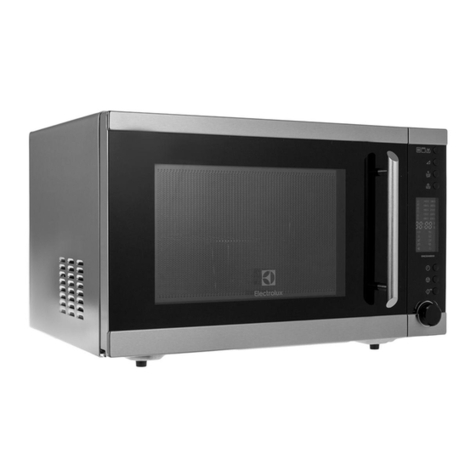
This Manual has been prepared to provide Electrolux Service Personnel with Operation and
Service Information for an Electrolux ICON High Speed Convection Microwave Oven Model
EW30SO75ESS.
Table of Contents
Section 1 Basic Information
Safe Servicing Practices.......................................... 1-1
Table of Contents .................................................... 1-2
Warnings and Safety Information ............................ 1-3
Precautions To Be Observed Before And During
Servicing To Avoid Possible Exposure To
Excessive Microwave Energy.................................. 1-4
Before Servicing ...................................................... 1-4
Danger High Voltage ............................................... 1-4
Before Servicing ...................................................... 1-5
When Testing Is Completed .................................... 1-5
Microwave Measurement Procedure USA .............. 1-6
Microwave Measurement Procedure Canada ......... 1-7
Product Specification............................................... 1-8
Grounding Instructions ............................................ 1-9
Oven Diagram ......................................................... 1-10
Section 2 Operation
Operating Sequence Description............................. 2-1
Off Condition ........................................................ 2-1
Cooking Condition................................................ 2-1
Variable Cooking ..................................................... 2-2
Preheat Convection Cooking Condition ............... 2-2
Convection Cooking Condition............................. 2-2
Speed Bake Cooking............................................ 2-3
Speed Grill Cooking ............................................. 2-3
Speed Roast Cooking .......................................... 2-3
Speed Cooking Of Automatic Cooking................. 2-3
Microwave Options Of Automatic Cooking........... 2-3
Oven Condition Schematics .................................... 2-4
Fire Sensing Feature (Microwave Mode.................. 2-6
Component Descriptions ......................................... 2-7
Door Open Mechanism............................................ 2-7
Door Sensing And Secondary Interlock Switches ... 2-7
Monitor Switch......................................................... 2-7
Thermistor ............................................................... 2-8
Magnetron Temperature Fuse................................. 2-8
Top Heater Thermal Cut-Out................................... 2-8
Side Heater Thermal Cut-Out.................................. 2-8
Top Heating Element............................................... 2-8
Side Heating Element............................................... 2-8
Turntable Motor ........................................................ 2-8
Fan Motor (Magnetron Side) .................................... 2-8
Fan Motor (Power Transformer Side)....................... 2-9
Convection Cooking System .................................... 2-9
Damper Open-Close Mechanism ............................. 2-10
Section 3 Troubleshooting and Testing
Warnings and Cautions ........................................... 3-1
Troubleshooting Guide Chart .................................. 3-2
Test Procedures ...................................................... 3-3
Section 4 Component Teardown
Warnings and Cautions ........................................... 4-1
Outer Case Removal............................................... 4-2
Terminal Insulator Removal..................................... 4-2
Power Supply Cord Removal .................................. 4-2
Back Plate Removal ................................................ 4-3
Power Transformer Removal................................... 4-3
Magnetron Removal ................................................ 4-4
High Voltage Capacitor And High
Voltage Rectifier Assembly Removal ...................... 4-4
Fan Motor Removal................................................. 4-5
Power Transformer Side ...................................... 4-5
Power Transformer Side ...................................... 4-5
Solid-State Relay (Magnetron Side) Removal......... 4-5
Damper Motor And Damper Switch Removal.......... 4-6
Heater Duct Left Assembly, Heater Duct Upper
Assembly And Convection Duct Assembly ............. 4-6
Side Heating Element Removal............................... 4-7
Turntable Motor Removal........................................ 4-7
Door Sensing Switch, Secondary Interlock Switch
and Monitor Switch Replacement/ Adjustment........ 4-8
Door Replacement And Adjustment ........................ 4-9
Section 5 Wire Diagrams
Wiring Schematic Oven Off Condition..................... 5-1
Backlit LED Diagram ............................................... 5-2
Function LED Diagram ............................................ 5-3
Pictorial Diagram ..................................................... 5-4
Power Unit Circuit.................................................... 5-5
CPU Unit Circuit ...................................................... 5-6
Key Function............................................................ 5-7
Section 6 Parts List
Parts Listing............................................................. 6-1
Control and Door Parts Exploded View................... 6-3
Cabinet And Frame Parts Exploded View ............... 6-4
Packing and Accessories Exploded View................ 6-5
