ELECTROTEK AW400TG TWO GAS User manual

ANAEROBIC WORKSTATION
AW400TG TWO GAS VERSION
MANUAL
44-45 Burnt Mill | Elizabeth Way | Harlow | Essex | CM20 2HU | United Kingdom
Telephone: +44 (0) 20 8551 7000 | Website: www.munroinstruments.com

1
CONTENTS
1.
GENERAL ARRANGEMENT DRAWING OF ANAEROBIC WORKSTATION
2
2.
GENERAL SPECIFICATION
3
3.
GAS SUPPLIES
4
4.
ELECTRICAL SUPPLES
4
5.
INSTALLATION OF GAS AND ELECTRIC DRAWING
5
6.
ASSEMBLY INSTRUCTIONS NO. 1. DRAWING
6
7.
ASSEMBLY INSTRUCTIONS NO. 2. DRAWING
7
8.
SPECIAL FEATURES
8
9.
CHECKING THE INCUBATOR ATMOSPHERE FOR OXYGEN
8
10.
PREPARING THE ANAEROBIC INDICATOR SOLUTION
9
11.
COMMISSIONING THE CABINET
10
12.
CHECKING THE GAS FLOW
11
13.
TRANSFERRING ITEMS INTO THE INCUBATOR
12
14.
TRANSFERRING ITEMS OUT OF THE INCUBATOR
12
15.
SINGLE PLATE ENTRY
12
16.
REMOVAL OF CONDENSATION FROM INSIDE THE INCUBATOR
13
17.
THE GAS TRAP BUBBLE BOTTLE
13
18.
THE HEATING AND GAS CIRCULATING SYSTEM
13
19.
THE TEMPERATURE CONTROLLER
13
20.
THE TEMPERATURE DISPLAY
14
21.
THE GAS CIRCULATION SYSTEM
14
22.
WORKING INSIDE THE CABINET WITH BARE HANDS
15
23.
GENERAL MAINTENANCE
16
24.
CHANGING THE CATALYST AND CONDITIONER
17
25.
CHANGING THE FLUORESCENT LIGHTING TUBE
17
26.
CLEANING
17
27.
TEST REPORT
18
28.
DECLARATION OF CONFORMITY
19
29.
CIRCUIT DIAGRAMS
Page

2
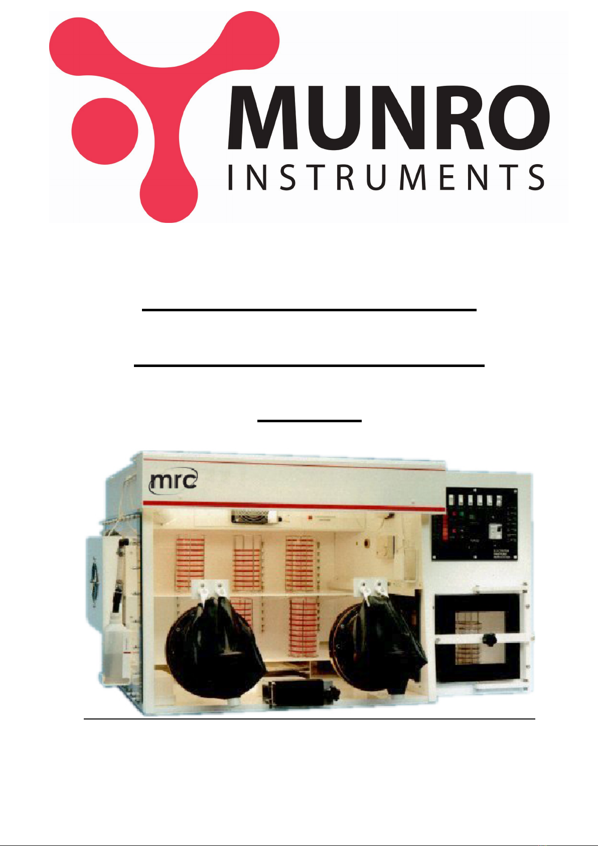
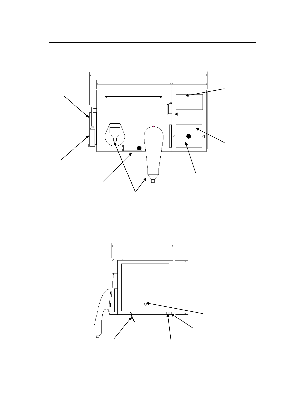
GENERAL ARRANGEMENT OF MUNRO AW400TG ANAEROBIC CABINET
DUAL GAS OPERATION - N2 & MIXED GAS (10% H2+ 10% CO2+ 80% N2)
DO NOT EXCEED 10% H2
Bubble bottle
Bare hand operation gauntlets
Flushing interlock
60 Petri dish capacity
Condensation Plate
Cooling air inlet
Manually sealed
interlock doors
Control panel
Anaerobic indicator bottle
Single plate entry
Omitted
Clear acrylic window
51” (1295mm)
33” (838mm) 15” (381mm)
27 ½” (698mm)
26 ¼” (667mm)
Electrical mains inlet
240V AC 50Hz
N
2
Gas Inlet
6mm dia. “push – in” connector
Gas outlet
Mixed Gas inlet
6mm dia. “push – in” connector

3
GENERAL SPECIFICATION
MODEL AW400TG
LOCK CAPACITY 60 Petri Dishes
MAIN CHAMBER INCUBATION CAPACITY 400 Petri Dishes
DOOR SEALING Manual
GASES 1) Mixed Gas (10% H2+ 10% CO2+ 80% N2)
2) Oxygen free Nitrogen N2
OXYGEN REMOVAL FROM AIRLOCK Positive Pressure flushing with catalyst
FABRICATION MATERIAL Acrylic
OVERALL DIMENSIONS Length 51" 1295mm
Depth 27 1/2" 698mm
Height 26 1/4" 667mm
ELECTRICAL SUPPLY 220/240 VAC 50Hz

4
GAS SUPPLIES
This Anaerobic Cabinet requires two gas cylinders, each fitted with a two stage regulator. The output
sides of the regulators should have a range of 0 - 50 p.s.i. (3.3 bar).
One gas cylinder should contain:
10% Hydrogen + 10% Carbon Dioxide + 80% Nitrogen
The other gas cylinder should contain:
Oxygen free Nitrogen
CAUTION: GAS CONTAINING MORE THAN 10% HYDROGEN SHOULD NOT BE USED
UNDER ANY CIRCUMSTANCES
The gas pressures at the inlets to the cabinet should be approximately 30 psi (2.0 bar) and the gas
flows are as follows:
MIXED GAS 25L/min
N2 25L/min
The diameter of the pipes connecting the cylinders to the cabinet should be selected according to the
length of run to give a minimum pressure drop, this will give maximum gas utilisation.
The cabinet is fitted with 6mm diameter "push in connectors" for the gases.
ELECTRICAL SUPPLIES
VOLTAGE: 220/240 V.A.C.
CURRENT: 5 AMPS
FREQUENCY: 50 Hz
CAUTION
Switching the Anaerobic workstation “OFF” before it has reached its working temperature can
cause the “THERMAL FUSE” protecting the heater to rupture.
We recommend that the heaters are switched off at the control panel if any work is being carried
out on the unit requiring switching “OFF” and “ON” or during any commissioning tests.

5
INSTALLING THE GAS AND ELECTRICAL SUPPLY TO THE AW400TG WORKSTATION
CAUTION:- GAS CONTAINING MORE THAN 10% HYDROGEN MUST NOT BE USED
UNDER ANY CIRCUMSTANCES
2 stage pressure regulator
Secondary gauge showing pipeline
pressure set between 1.6 and 2.5 Bar
sufficient to switch low gas pressure
indicator “OFF”
Primary gauge showing
pressure in bottle
Regulator
Gas isolation
taps close to
cabinet.
6mm diameter flexible
plastic tube 1m long
Electrical supply 220/240V AC 50Hz
Mount cabinet on strong
bench at convenient
height
Select tube diameter to give
minimum pressure drop when 25 L
of gas per minute is flowing.
Diameter depends on length of run
Large gas cylinder containing 9 cubic
meters of mixed gas.
10% H2+ 10% CO2+80% N2
Low gas pressure
indicator
Gas cylinder containing 9 cubic
meters of oxygen free nitrogen

6
AW400TG ASSEMBLY INSTRUCTIONS NO. 1 DRAWING
Place condensation collection
bottle here inside incubator and
fit collection pipe from cool plate
Conditioner
Catalyst
Hang indicator pump
here and plug into
adjacent socket
Clip anaerobic indicator
bottle here
Place conditioning sachet
and palladium catalyst
sachet in channel under
shelf in order shown
Fit small sachet of
catalyst inside roof of lock

7
AW400TG ASSEMBLY INSTRUCTIONS NO. 2 DRAWING
Insert “Mains Failure” battery and battery
holder here
Seal gauntlets with “bungs”
when not in use
Dust both “Wrist Cuffs” with powder
before inserting arms into gauntlets
Gauntlet holder
Hang gauntlet on “Gauntlet
Hooks” with “Gauntlet Holders”
when not in use
Fix gauntlet assembly to “Arm Ports” with
“O” rings – ensure there are no creases in
the gauntlets underneath the “O” rings to
prevent gas leaks
“Push Rod” used
to insert dishes
into incubator
Fit “Bubble Bottle”
here and fill up to line
with water
Arm Ports
Gauntlet
hooks
Bung
Gauntlet
assembly
“O” ring
Powder

8
THE MUNRO AW400TG ANAEROBIC WORKSTATION SPECIAL FEATURES
Many special features have been designed into the MUNRO Anaerobic Workstation that cannot be
found on any other cabinet. All these have been built in for safety, economy of operation and to make it
easier and more comfortable for the operator to use.
MINIMUM BENCH AREA
Although the cabinet will incubate 400 dishes there is still ample room within the unit for the operator to
manipulate the cultures.
OPERATOR COMFORT
Quite often the operator has to spend long periods of time working with their arms inside the unit and for
this reason the cabinet has been designed so that the operator can work sitting down thereby minimising
fatigue. The openings of the glove ports are large, facilitating easy movement of the arms. The viewing
area is large, unobstructed by bends in the material which cause the operator to be constantly moving
their position. The doors are easily sealed by first closing, then turning the tightening knob. If the unit fails
to function because one of the doors has been left open or perhaps a gas bottle has run out of gas then
this is indicated clearly on the Control Panel. The unique bare hand working facility allows the operator to
get their hands in and out of the cabinet without any fuss. In fact the cabinet has been designed to be
very user friendly.
SINGLE PLATE ENTRY LOCK
This lock is used when only a small number of dishes need placing in the incubator. It saves both time and
gas. The front door is opened by unscrewing the hinge pin and the dish is placed in the cabinet by pushing
it with the bar provided. The dish lid travels up a ramp allowing the escaping gas from the cabinet to flush
the air out of the dish before the lid is replaced by the back door. Once the dish is in the incubator the
outer door is re-closed by tightening the screw.
CHECKING THE INCUBATOR ATMOSPHERE FOR OXYGEN
The Anaerobic Indicator Solution will indicate traces of Oxygen in the incubator atmosphere by changing
colour from being clear when the atmosphere is anaerobic to being blue when oxygen is present. The
Indicator Solution is held in a small bottle located at the front of the incubator in the top right hand corner
and held in position by a plastic spring clip. The atmosphere from the cabinet is bubbled through the
solution by a small aquatic pump. The pump is plugged permanently into an electrical socket and the
switch should be left in the "ON" position. The atmosphere of the incubator can be checked for oxygen
content by simply switching the socket "ON" on the Control Panel. It is usually sufficient to check the
atmosphere perhaps once a day allowing the pump to run
for about 1 minute.

9
PREPARING THE ANEROBIC INDICATOR SOLUTION
Make up the Anaerobic Indicator Solution from the two ingredients provided, sufficient to fill the bottle
about 1/2 full using nine parts of solution "A" and one part of solution "B"
Now place a cap lightly on the neck of the bottle and place it in a bath of water and bring it to the boil. The
solution will change from being blue to colourless. Tighten up the cap and remove the bottle from the
water allow it to cool and pass it into the cabinet. The cap can now be removed and the outlet pipe from
the pump connected to the bottle. The bottle can now be placed in position inside the bottle holder where
it will be in full view.
We recommend replacing the solution on a weekly basis.

10
COMMISSIONING THE CABINET
Check all the following points before starting to commission the workstation.
1. Switch "OFF" the cabinet at the Mains ELCB switch
2. Open both the Mixed Gas and the N2regulators, set the secondary gauges to give a maximum
pressure of 30 psi at the inlets to the unit with the gases flowing
3. Ensure that the Gas Trap Bubble Bottle is filled up to the water level line and the gauntlets and
bungs are both fitted to the cabinet. (Page 7)
4. Hang the Indicator Pump on the hook adjacent to the electrical socket, plug the pump into the
socket and switch "ON". Place the Anaerobic Indicator Bottle in position, filled to the appropriate
level with Indicator Solution and connected to the pump with the flexible tubing. (See Instructions
regarding preparation of the solution on (Page 9)
5. Check that the Atmospheric Conditioning Sachets and the Palladium Conditioning Sachets are in
position underneath the shelf. The Atmospheric Conditioning Sachets should be put in first to the
rear of the cabinet. Place the small Palladium Catalyst in the roof of the Lock.
(See Sketch on Page 17)
6. Now switch on the cabinet at the ELCB. If either of the "Low Gas Pressure" neons is illuminated,
increase the appropriate gas pressure until the neon goes out.
7. Switch the light "ON"
8. Check that the heater fans are working and that the heater light is illuminated.
(see WARNING NOTE regarding Thermal Fuse).
9. Switch the Socket "ON" and the Anaerobic Indicator Solution should turn blue.
10. Switch the Dehumidifier "ON" and set the humidistat to 70% RH. (Relative Humidity)
11. After closing all the doors, slide the clip on the Commissioning Switch and switch "ON". Press the
"Lock Flush" button and gas will start to flow in pulses into the Cabinet.
12. The gas flow has been set to 25 litres per minute at the Factory and should not require adjustment
(See Page 11)
13. Leave the Commissioning Switch in this position for one hour or until the Anaerobic Indicator turns
colourless.
14. At this stage the cabinet is anaerobic. Switch the Commissioning Switch "OFF" and replace the
clip to prevent switching it on accidentally.
15. The temperature of the unit will take several hours to settle down.
16. Now check all the functions are working.

11
CHECKING THE GAS FLOW
The Gas Flows and Pressures have been set at the factory and should not require adjustment.
To check the Gas Flow into the Workstation the following equipment is required:
1. Gas Flow Meter (0 – 30 Litres per minute)
2. Pressure Gauge (0 – 3.3 Bar)
Connect up the equipment as shown and start the “Lock Flush”
Disconnect the gas supply to the cabinet at point ‘X’ and insert a flow meter. The meter should
vent to the atmosphere.
Any adjustment to the gas flow should be made using the “Flow Regulator” situated at the end of
the gas train.
Inlet Pressure Switch
Flow Meter
Pressure Gauge
Pressure Regulator –
Outlet Pressure set at 1 Bar
Inlet Solenoid
Flow Regulator
X

12
TRANSFERRING ARTICLES IN AND OUT OF THE CABINET
TRANSFERRING ITEMS INTO THE INCUBATOR
The Workstation is supplied with two stainless steel Petri Dish Holders each capable of holding fourty Petri
Dishes together with four powder coated ten dish holders. These are used for transferring dishes into and
out of the cabinet and stacking them whilst they are being incubated.
To get dishes into the incubator simply load up the Holders and open the 0uter Door by turning the knob
and placing the holder inside the lock. When the door is re-closed, the atmosphere inside the lock is made
Anaerobic by pressing the "Start Lock Flush" button.
The atmosphere within the lock is automatically replaced several times until the oxygen content is
sufficiently low to allow the Inner Door to be opened. At the end of the flushing operation which takes five
minutes, the "Lock Anaerobic" Indicator on the Control Panel will become illuminated.
At this point place the hands inside the incubator using the glove ports (see Working inside the cabinet
with bare hands Page 15). Open the Inner Door and transfer the contents of the "Lock" into the incubator
section of the unit.
TRANSFERRING ITEMS OUT OF THE INCUBATOR
To unload the contents of the incubator check that the Neon Indicator inside the cabinet is not illuminated
then open the Inner Door, place the items into the Lock and re-close the Door. Withdraw the arms from
the glove ports and seal them. The items can now be removed from the cabinet by Opening the 0uter
Door.
SINGLE PLATE ENTRY
Single dishes can be placed into the incubator by opening the small door situated between the two glove
ports and pushing them into the cabinet with the bar provided. The positive pressure within the cabinet
ensures that no oxygen enters the unit during this operation.
CAUTION: TAKE CARE NOT TO DAMAGE THE DOOR SEAL WITH ANY SHARP
OBJECTS WHILST CARRYING OUT THE ABOVE OPERATIONS.

13
THE REMOVAL OF CONDENSATION FROM INSIDE THE INCUBATOR
Water vapour accumulates inside the incubator atmosphere from two sources, firstly from the evaporation
of the media in the Petri dishes and secondly by the hydrogen and the traces of oxygen being linked
together by the palladium catalysts. If this water vapour is not removed it will condense on the cooler
surfaces of the incubator walls and form pools of water. The cabinet however is fitted with a large
aluminium Condensation Plate which is kept a few degrees lower than the temperature inside the
incubator by a fan which blows cool air from the room onto its outer surfaces. This reduction in
temperature is sufficient to cause the excess water vapour inside the incubator to condense, run down its
surface and collect at the bottom and finally fall via a drain tube into the collection bottle situated inside the
cabinet. When this is full, remove it via the lock.
The fan for the Condensation Plate can be switched "OFF" at the Control Panel if the Service Engineer is
working on the unit. The humidity within the incubator is controlled by the Humidistat which is mounted just
above the inner door. The Humidistat switches the fan "ON" and "OFF" automatically.
THE GAS TRAP BUBBLE BOTTLE
The Gas Trap Bubble Bottle is mounted on the incubator endplate just beneath the Condensation Plate
and has several functions. Firstly, it is a safety device so that in the event of a gas Input Solenoid
remaining open, the gas has a way of getting out of the cabinet and not doing any damage to the structure
of the unit. Secondly, it allows the operator to be able to push their arms inside the cabinet without
applying undue pressure. It must be remembered that all gas that gets out of the cabinet via the bubble
bottle is wasted and therefore every effort must be made to minimise this when working inside the
incubator. If one arm is withdrawn as the other arm is pushed into the unit, gas wastage can be reduced.
THE HEATING AND GAS CIRCULATING SYSTEM
The heating and gas circulating system consists of one tubular 400 Watt heaters fixed directly behind the
fan units mounted on detachable plates in the top of the incubator. The fans run continuously whilst the
heater is burst fired.
THE TEMPERATURE CONTROLLER
An adjustable electronic temperature controller fitted in the control panel of the cabinet regulates the
temperature. The controller has a temperature sensor in the right hand top corner of the heating chamber
and the temperature of the incubator can be adjusted between 3 degrees C above ambient to 40 degrees
C. There is a green led incorporated in the temperature controller which indicates when the heater is
operating and a temperature display to give an accurate reading of the internal temperature of the cabinet.
A data sheet covering the temperature controller is included with this documentation.
.

14
THE GAS CIRCULATION SYSTEM
The fan units pick up the cooler incubator atmosphere which has been forced to the top of the incubator
and first passes it over the warm heaters. This warmer gas is now forced down the channel at the back of
the cabinet and passes under the bottom shelf of the incubator where it first meets the sachets of
Conditioner and then the sachets of Catalyst. The gas now gives up just sufficient of its heat to maintain
the required temperature before finding its way back to the top of the incubator due to the suctional force
of the fan.

15
WORKING INSIDE THE CABINET WITH BARE HANDS
Although the MUNRO cabinet can be used with long sleeved gloves it is much easier to work with bare
hands. This bare hand facility is achieved in a very simple but effective way. The Bare Hand Gauntlet
Assembly consists of four components as shown in diagram 1.
1. Sleeve 2. Solid Ring 3. Cuff 4. Bung
The inside of the sleeve is always held at positive pressure by the Gas Pressure Switch, therefore if the
Bung is removed from the Cuff, gas will flow out of the cabinet and no oxygen will enter.
To insert the hand into the cabinet simply lift up the end of the gauntlet and push the Bung into the cabinet
using the tips of the fingers only, followed by the hand (Note: - Do not grip the end of the bung with the
fingers). The Cuff will seal around the wrist as shown in diagram 2. Now place the Bung inside the
cabinet in a convenient position.
To remove the hands from inside the cabinet, simply collect the Bung and release it within the sleeve.
Remove the hand and let the Bung fall into the Cuff where it will seal. Gravity will now hold the Bung in
place. Do not attempt to pull the bung back into the cuff.
ALWAYS ALLOW THE SLEEVE TO FILL WITH GAS BEFORE INSERTING OR WITHDRAWING THE
HAND.
If the hands and Cuffs are lightly dusted with talcum powder the operation becomes very simple.
If the Cuffs are too tight around the wrists they can be trimmed to a more comfortable fit with a sharp pair
of scissors. However they must be sufficiently tight to prevent gas escaping whilst working inside the
cabinet.
Two hooks are provided just above the arm ports together with a Gauntlet Holder for use when the
Gauntlets are not being used. If the Gauntlet is fitted into the Gauntlet Holder about half way up its length,
the Holder can be clipped onto the hook. This has two effects: firstly it prevents the Gauntlets hanging
down and getting in the way and, secondly, it greatly reduces condensation in the Gauntlet Assemblies.
Diagram 1
Diagram 2

16
GENERAL MAINTENANCE
The MUNRO Workstation, unlike other units, uses the energy contained in the gas bottles to do most of
the work required. This means that there are no evacuation or circulation pumps to maintain.
Many of the components used in the construction of the unit are available "off-the-shelf" in almost every
part of the world. However, all spare parts are readily available from MUNRO.
We recommend that the items below are replaced as indicated. However experience shows that they last
approximately twice this period.
RECOMMENDED LIST OF SPARES AND REPLACEMENT PARTS FOR AW500TG
Quantity Description Recommended Replacement
2 Gauntlets 1 year
2 Cuffs 6 months
3 Fans 2 years
2 Heaters 3 years
1 Outer Door Seal 6 months
1 Inner Door Seal 6 months
1 Single Port Door Seal 6 months
2 Large "O" Rings 6 months
6 Small "O" Rings 6 months
1 Spotlight Bulb 2 years
2 Catalyst Sachet Large 2 years
1 Catalyst Sachet Small 2 years
2 Sachet Conditioner 1 year
1 Alarm Battery 1 year
SCHEDULE OF RECOMMENDED PREVENTATIVE MAINTENANCE TASKS FOR AW500TG
Task Interval
Check operating temperature 6 months
Check thermometer 6 months
Check solenoid seals 2 years
Check gas flow and recalibrate 6 months
Check for gas leaks 6 months
Change alarm battery 6 months
Check ALL functions are operating 6 months
WE RECOMMEND THAT ALL THE ABOVE MAINTENANCE WORK IS CARRIED OUT BY
A TRAINED SERVICE ENGINEER

17
CHANGING THE CATALYST AND CONDITIONER
The sachet of Catalyst and the sachet of Conditioner which are housed beneath the bottom shelf of the
incubator will require replacing at a period in excess of one year. If for any reason the sachet of catalyst
gets wet, the contents can be dried out by heating to a temperature of 160°C for a period of two hours.
The sachet of conditioner can, if necessary, be dried at room temperature. The chemicals can then be
returned to their respective containers for further use.
When replacing the sachets, ensure that the sachets of Atmospheric Conditioner are at the REAR of the
cabinet so that the gas passes over them first. (See sketch below)
There is also a sachet of catalyst housed in the roof of the lock. This sachet can be both inserted and
removed by bending it slightly and sliding it in or out of the holder.
CHANGING THE FLUORESCENT LIGHTING TUBE
Switch off the power to the light on the Control Panel and remove the three screws from the top and the
two plastic screws from the front of the Light Shade. The tube can now be removed from its Holding Clips,
the end caps disconnected and the new tube fitted.
CLEANING
The inside of the cabinet can be swabbed out with a weak solution of general laboratory detergent and
warm water, and dried with a soft cloth. In the event of a culture spillage, a 5% Hypochlorite solution
should be applied to the area and left for half an hour. It should then be wiped and swabbed with a 1%
solution of Sodium Thiosulphate. Remove the catalysts and conditioners from the unit while the
Hypochlorite solution is being used.

18
TEST RECORD SHEET
MODEL AW400TG
SERIAL NO 7393
CUSTOMER PUNMICRO
FLUSH CYCLE 4 SECONDS ON 2 SECONDS OFF
FLUSH DURATION N2 - 3 MINUTES, MG - 2 MINUTES, TOTAL 5 MINS
MIXED GAS FALLING CUT OUT PRESSURE 23 PSI
MIXED GAS RISING SWITCH ON PRESSURE 27 PSI
N2GAS FALLING CUT OUT PRESSURE 24 PSI
N2GAS RISING SWITCH ON PRESSURE 30 PSI
MIXED GAS FLOW 25 L / MIN
33L / LOCK FLUSH
N2 GAS FLOW 25 L / MIN
50L / LOCK FLUSH
MIXED GAS INPUT PIPE SIZE 6 mm DIA
N2 GAS INPUT PIPE SIZE 6 mm DIA
INCUBATOR POSITIVE PRESSURE SETTING 6 mm WG
INCUBATOR LEAK NOT DETECTED 1 HOUR
TEMPERATURE SETTING 36.5 deg C
OVER TEMP SETTING OF THERMAL FUSE 96 deg C
LIGHT INTERNAL SOCKET
SPOTLIGHT COMMISSIONING SWITCH
HUMIDISTAT INNER DOOR
MIXED GAS FLOW OUTER DOOR
N2GAS FLOW DEHUMIDIFIER
LOCK FLUSH LOCK ANAEROBIC GAS FLOW
ALARMS GAS LEAK SETTING 2 MINS.
ELCB
CHECKED BY DATE

19
Declaration of Conformity
Equipment Anaerobic Incubator type AW400TG
Manufacturer MUNRO Ltd
Address 44-45 Burnt Mill, Elizabeth Way, Harlow, Essex,
CM20 2HU, UK
Description of Equipment. Incubator for the environmentally controlled incubation of
anaerobic bacteria.
I certify that the apparatus identified above conforms to the requirements of Council Directive
89/336/EEC
Signed Date
Position/status Director.
Table of contents
Other ELECTROTEK Desktop manuals
Popular Desktop manuals by other brands

HP
HP Pro 3420 Maintenance & service guide

micronPC
micronPC Millennia XP+ user guide

Lenovo
Lenovo ideacentre 310A Series Hardware Maintenance Manual

HP
HP Workstation zx6000 Quickspecs

IBM
IBM NetVista A20 quick reference

HP
HP Compaq Business Desktop dx2000 uT Series Product End-of-Life Disassembly Instructions