Elekitsorparts FUNtronics NPR-70 User manual


Elekitsorparts Store Item Name: NPR-70 Modem Item No.: H10015K Document Type:Assembly Guide
2
Description
Thank you for purchasing NPR-70 New Packet Radio modem. The NPR-70 modem was designed by the French Ham F4HDK
and posted on the hackaday website. This is a fully open source modem both on hardware and software. NPR refers to the
New Packet Radio protocol. Through this protocol, the rate of bidirectional IP data transmission can go up to 500kps. This
baudrate is much better than the traditional old-fashioned Packet Radio protocol based on AX.25. Therefore, this Modem can be
a good choice for extending an existing 5.6GHz Hamnet, and can temporarily be used as an effective tool for accessing to DX
Summit and DX Spot information from outdoor. Authorized by the original author F4HDK, elekitsorparts.com is proud to
produce the NPR-70 modem kit. The following content is the assembly guide for this kit. For more information on the NPR-70
modem, please refer to the following website, https://hackaday.io/project/164092
Our assembly guide will be divided into two major steps, each step is divided into a number of small sequences, each of which
has a detailed description on the parts needed and assembly guide. In order to ease the soldering difficulty, all of the SMD parts
except the RF4463F30 are factory assembled on the PCB. You just need to solder the Through Hole parts only. The first step is
to solder the through hole parts, while the second step is the guidance for installing the modem pcb into its enclosure.
NPR-70 v05 is an upgrade for NPR-70 v04, the v05 adds a spi-SRAM chip on board in order to improve the performance while
transmitting. In order to use the external SRAM, please keep the modem’s firmware with the newest update.
Before Assembling
Tools Required in Assembling Electronic Kits
You will need the following tools to build this kit:
•Fine-tip temperature-controlled ESD-SAFE soldering station with 700 to 800°F tip (370-430°C). Recommend a spade tip
no greater than 0.05” (1.3 mm) wide.
•High wattage (approx.100 watt) soldering gun to solder the BNC connectors. Use this iron only where directed in the
procedure. Use the temperature-controlled station for all other soldering.
•IC-grade, small-diameter (.031”) solder (Kester #44 or equivalent). Small diameter solder I is important to avoid filling
adjacent solder pads and creating solder bridges.
•Small, #2 Phillips screwdriver.
•Needle-nose pliers.
•Small wrench or driver for 6-32 nut.
•Small-point diagonal cutters. Flush-cutting type required (Xcelite MS54-5J or equivalent).
•Digital Multimeter (DMM) with voltage, resistance and diode-checking functions. A DMM with capacitance measurement
capability is desirable, but not required.
•Magnifying visor or magnifying glass with a hands-free stand.
•Desoldering tools and supplies are invaluable. Narrow solder wick or a good vacuum desoldering tool such as the
Soldapullt® model DS017LS are recommended.
•Small, #2 (1.4 mm wide) blade screwdriver may be required.
We strongly recommend that you use a conductive wrist strap and anti-static mat while handling the MCU or the PC boards
with the MCU installed. Wrist straps and mats are available at very low cost from Jameco, Mouser, and other electronics
suppliers.

Elekitsorparts Store Item Name: NPR-70 Modem Item No.: H10015K Document Type:Assembly Guide
3
Step 1
We are going to install the RF module, and all of the through-hole parts, modules, DC port and toggle switch in this step. Here
Elekitsorparts Store Item Name: NPR-70 Modem Item No.: H10015K Document Type:Assembly Guide
4
are the parts that we need in this step.
Sequence
Designator
Value
Quantity
needed
Quantity
supplied
Footprint
Category
1
RF4463F30
1
1
2
Male Pin Header 2.54 x 4
1
1
LM2596 Module
1
1
Module
3
W5500 Lite
1
1
Module
4
Female Pin Header 2.54 x
15
2
2
Female Pin Header 2.54 x 1
1
1
STM32 L432KC
1
1
Module
5
Y, G
1
1
R, R
1
1
6
L4940_5V
1
1
TO-220
7
LM2937_3V3
1
1
TO-220
8
SMA Right Angle Long
1
1
9
DC 2.1 Port
1
1
Toggle Switch 5mm
1
1
AWG22 Wire Red 80mm
1
1
AWG22 Wire Black 80mm
1
1
Heat Shrink Tube 3mm x
60mm
1
1
10
SB1, SB2,
SB3, SB4
Power supply jumpers
1Sequence 1
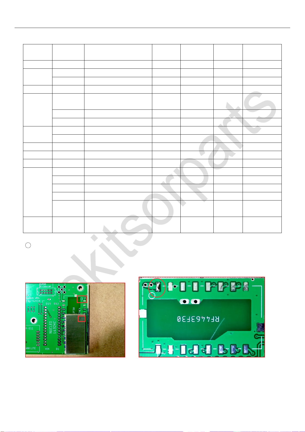
Parts Needed: RF4463F30 x 1, Soldering Position: RF4463F30, Package type: N/A
First of all, have one of the corner solder pads tinned, just as the picture below, at the same time, pay attention to the
direction of the module. Both of the PCB and the RF module have a circle mark at one corner for indicating starting pin.
Then put the module on the PCB and solder the first pin, the module will finally be held on the PCB when done.
Elekitsorparts Store Item Name: NPR-70 Modem Item No.: H10015K Document Type:Assembly Guide
5
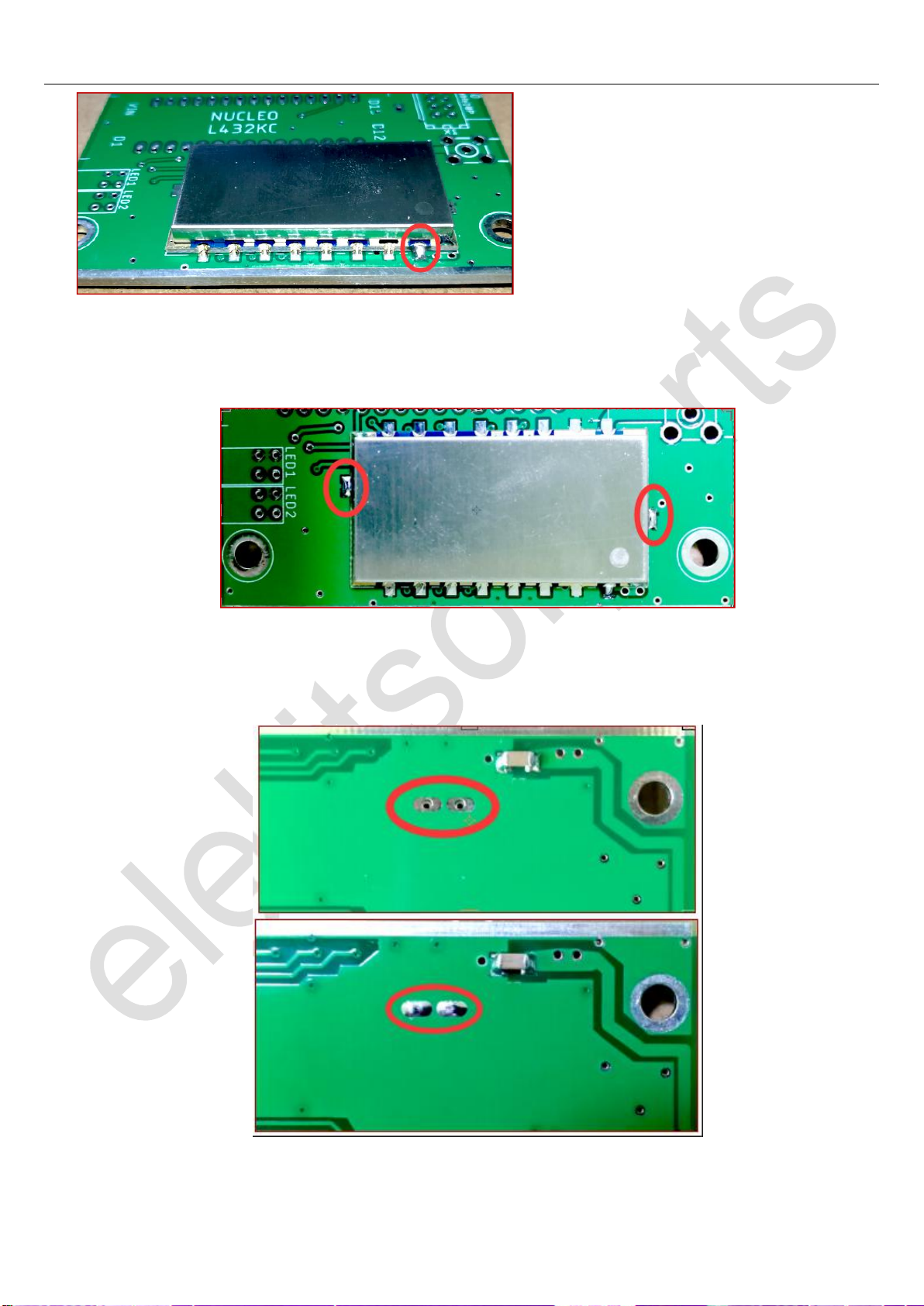
Adjust your soldering iron to the highest temperature that it can go. Solder the 2 pins indicated in the picture below.
Because these 2 pads are connected to GND, and the large areas of copper will cause heat to dissipate quickly, so please keep
the tip of your solder iron stopping on the solder pad for a sufficient amount of time to ensure that the solder is completely
melted.
Next, turn the PCB over to another side. Please solder 2 through-hole pins under the RF module. Keep in mind, these 2
pins connected to the PCB’s GND also, so make sure all of the solder are melted properly and the melted solder will go
through the hole to the bottom of RF module. When it is done, the RF module and the main PCB will keep together.
Now let’s solder the rest pins, it should look like this when it is finished.
Elekitsorparts Store Item Name: NPR-70 Modem Item No.: H10015K Document Type:Assembly Guide
6
Till now, all of the SMD parts have been soldered, please carefully check back at least once in order to ensure the success
of building. Let’s move on to Step 2.
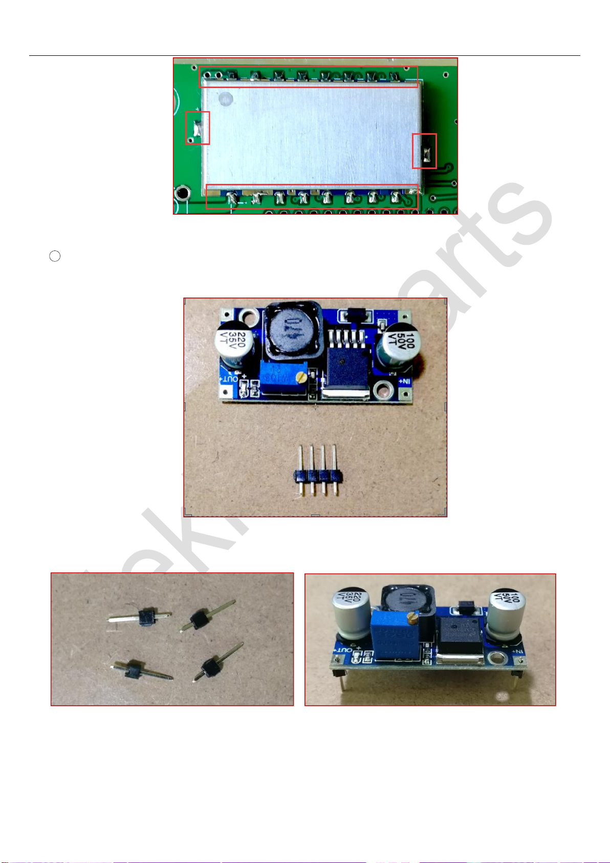
2Sequence 2
Parts Needed: Male Pin Header 2.54 x 4,LM2596 Module
First all, break the 4-pin male header into 4 pieces, and then insert them into the 4 soldering holes on LM2596 module, see
the picture below.

Elekitsorparts Store Item Name: NPR-70 Modem Item No.: H10015K Document Type:Assembly Guide
7
Finally, solder them onto the module. Please keep the leg of the pin header straight when soldering, as we have to insert
the module onto the main PCB later.
Next, apply a 12V DC source to the IN port of this module, meanwhile use a DVM to measure the voltage coming out of
the OUT port. A led on the module should be ON when a DC power source is applied. Now use a flat head screwdriver to
trim the blue potentio-meter while monitoring the output voltage with your DVM. Please rotate the potentio-meter
clockwise or counter-clockwise until the output voltage is 6.5V. Finally, install the module onto main PCB and solder the 4
pins at the bottom side of PCB.
3Sequence 3
Parts Needed: W5500 Lite Module x 1

Elekitsorparts Store Item Name: NPR-70 Modem Item No.: H10015K Document Type:Assembly Guide
8
4Sequence 4
Parts Needed: Female Pin Header 2.54 x 15 x 2, Female Pin Header 2.54 x 1, STM32 L432KC x 1
We have to solder the female pin headers to the main PCB, and then insert STM32L432KC module to the female pin
headers.

Elekitsorparts Store Item Name: NPR-70 Modem Item No.: H10015K Document Type:Assembly Guide
9
Notes on STM32L432KC: The are some important solder joints on STM32L432KC Module board, and 2 or 3 of them
should be dis-soldered in order to configure our modem to work remotely or normally. It is really a tough job to dis-solder
these tiny jumpers on the board, so we have done this job for our users. The solder joint SB9 is the key for configuring the
modem in “Remotely Manageable“ or “Normal” working mode. The modem will work in normal mode if we have SB9
dis-soldered and if SB9 is soldered again, the modem will work back to in remotely manageable mode. You may
solder or dis-solder SB9 again in the future for configuring the modem into the 2 proposed modes. For the detailed
explanation on these jumpers and the two working modes, please refer to F4HDK’s document on hackaday project
page (NPR_modem_assembly_guide and NPR_advanced_guide).
5Sequence 5
Parts Needed: LED1 (Y, G) x 1, LED2 (R, R) x 1
Install the 2 LED Modules to the main PCB and solder them. Please pay attention to distinguish the color of the LEDwhen
installing.
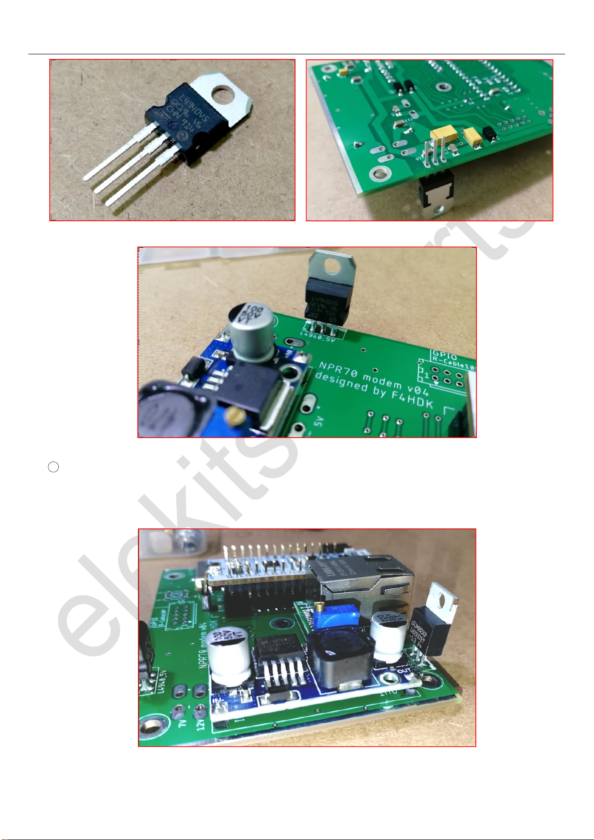
6Sequence 6
Parts Needed: L4940_5V x 1
Now install the L4940_5V to the main board.
Elekitsorparts Store Item Name: NPR-70 Modem Item No.: H10015K Document Type:Assembly Guide
10
7Sequence 7
Parts Needed: LM2937_3V3 x 1
Now solder the LM2937_3V3 to the main board.
Elekitsorparts Store Item Name: NPR-70 Modem Item No.: H10015K Document Type:Assembly Guide
11
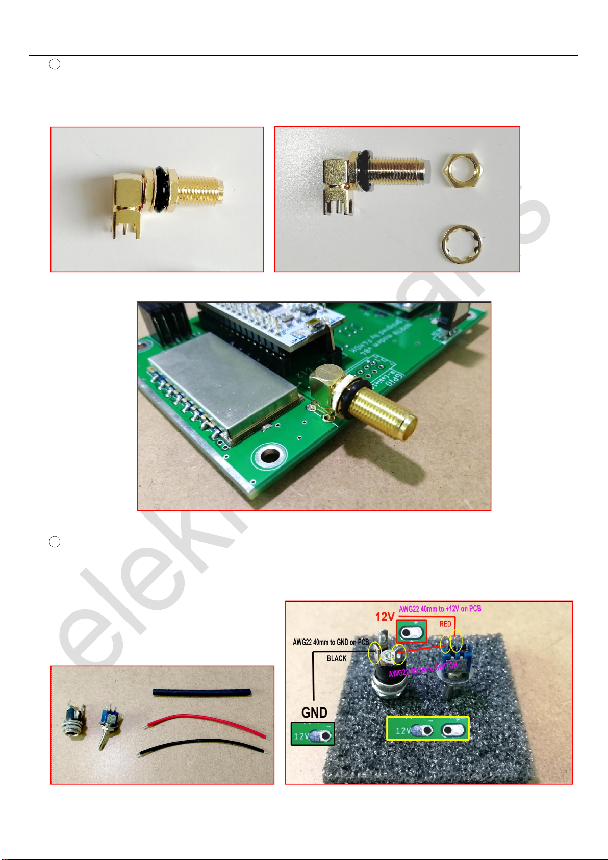
8Sequence 8
Parts Needed: SMA Right Angle Long x 1
Take the SMA port out, remove the outer washer and nut, and solder it to the main board. Please make sure your solder
iron has sent the maximum power out when soldering, as the outward 4 pins are connected to GND.
9Sequence 9
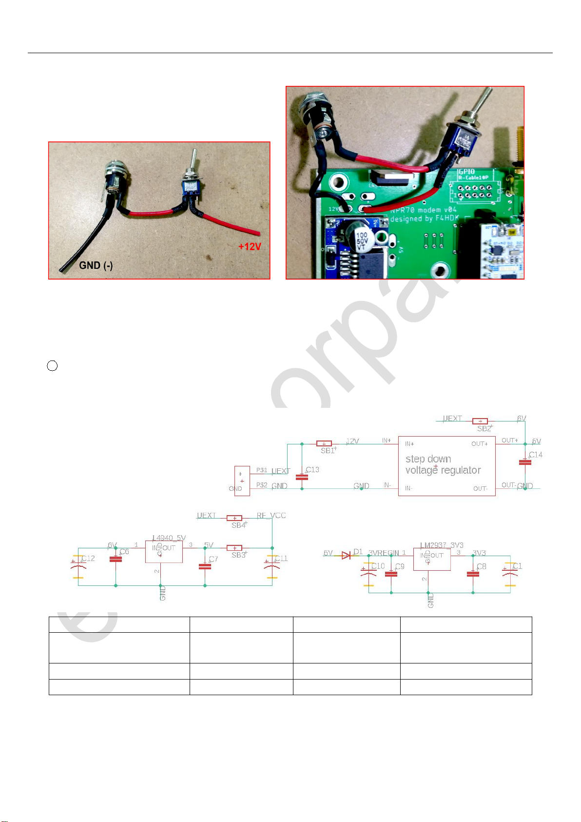
Parts Needed: DC 2.1 Port x 1, Toggle Switch 5mm x 1, AWG22 Wire Red 80mm x 1, AWG22 Wire Black 80mm x 1,
Hot Shrink Tube 3mm x 60mm x 1
Please install the DC PORT and Toggle Switch as the wiring diagram shows.
Elekitsorparts Store Item Name: NPR-70 Modem Item No.: H10015K Document Type:Assembly Guide
12
Now, apply a 12V DC power source to the modem, and switch it ON. If everything goes fine, the PWR led will be on. The
CON led and RX led will be flashing initially, then they go OFF, so as the TX led. The PWR led always keeps ON. If your
modem doesn’t behave like this, please carefully inspect all of the previous sequences and steps. You have to make sure
everything works fine before going to next step.
10 Sequence 10
Unlike NPR-70 v04, NPR-70 v05 has 4 option jumpers on board, they allow you to power the modem by 12V, 6V or 5V
DC power supply, here is a table for describing the power supply choices.
Power Supply Option
Soldering
Dis-soldering
Other Notes
Powered by 12V DC
SB1, SB3
SB2, SB4
Default option for the factory
assembled units
Powered by 6V DC
SB2, SB3
SB1, SB4
Powered by 5V DC
SB4, SB2
SB3, SB1
We would like to power the modem by a 12V or 13.8V DC, so we have to solder SB1, SB3, and keep SB2 and SB4
dis-soldered. See the picture below:

Elekitsorparts Store Item Name: NPR-70 Modem Item No.: H10015K Document Type:Assembly Guide
13
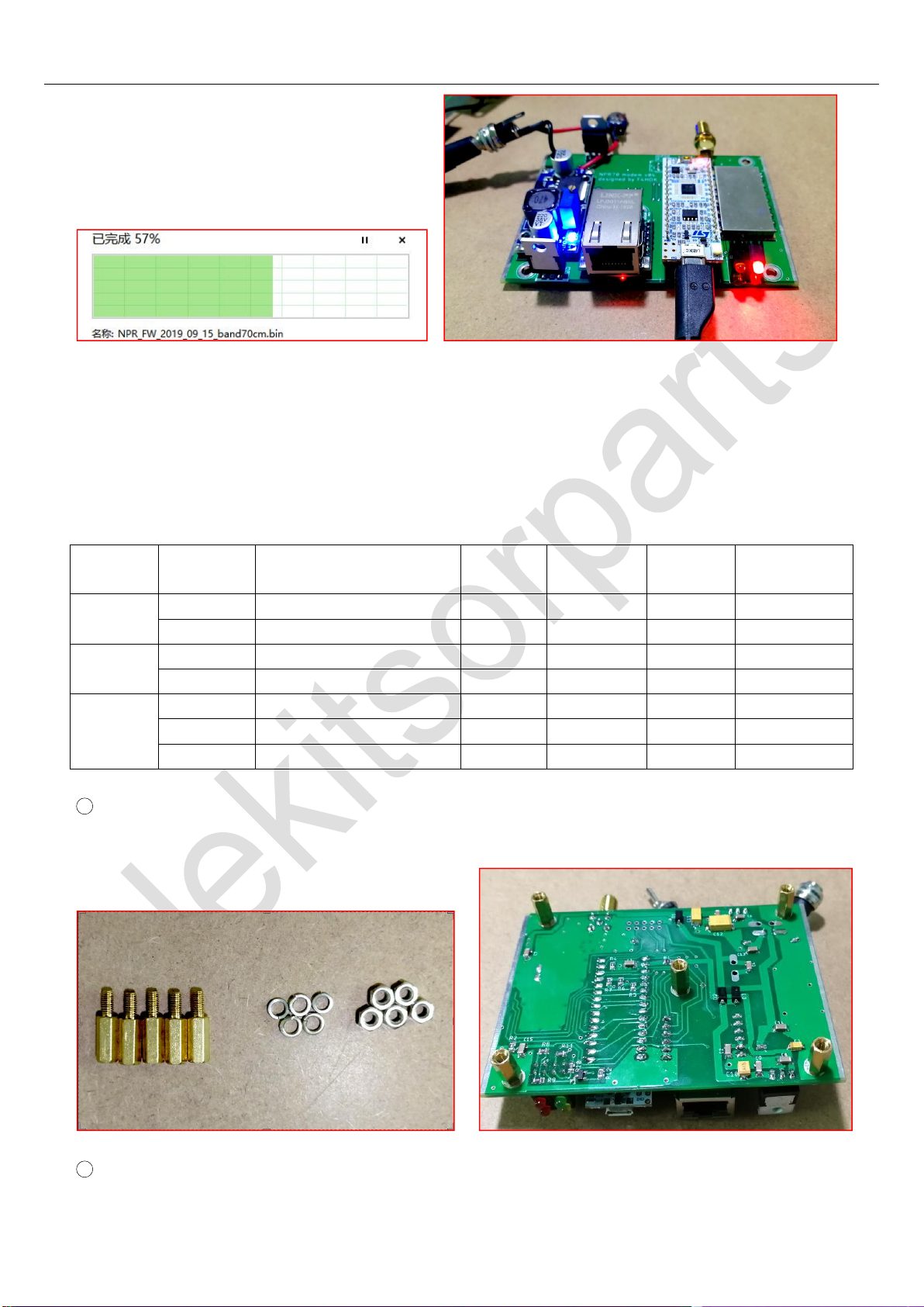
Note on flashing firmware: We have flashed the STM32 board with the newest firmware and upgraded the built-in
ST-LINK to the newest version before shipment. For the future firmware upgrade, please do it according to the following
instructions.
Go to NPR-70 project page on hackaday (https://hackaday.io/project/164092), and download the newest firmware
(NPR_FW_2020_02_23_band70cm) to your PC. Apply a 12V DC power source to the modem, then switch it ON.
Connect the modem to your PC via the supplied Micro-USB cable. Your PC will find a new storage device and assign it a
new Disk Drive symbol just as the picture shows below.
Elekitsorparts Store Item Name: NPR-70 Modem Item No.: H10015K Document Type:Assembly Guide
14
To flash a new firmware, just copy the firmware file and paste it to this new Disk Drive. When finished, unplug the USB
cable and switch off the unit.
Step 3
In this step, we will put the modem board into its enclosure, and finally screw it on. Here are the parts needed in this step.
Sequence
Designator
Value
Quantity
needed
Quantity
supplied
Footprint
Category
1
Copper Posts M3 x 12mm
5
5
Washers & Nuts M3
5
5
2
Screws M3 x 6mm Black
15
15
Enclosure
2
2
3
Rubber Feet
4
4
Master or Client Sticky Tape
2
2
Micro-Usb Cable
1
1
1Sequence 1
Parts Needed:Copper Posts M3 x 12mm x 5, Washers & Nuts M3 x 7
Attach the copper posts to the board, pad the spring washers and lock the nuts, as the picture shows below.
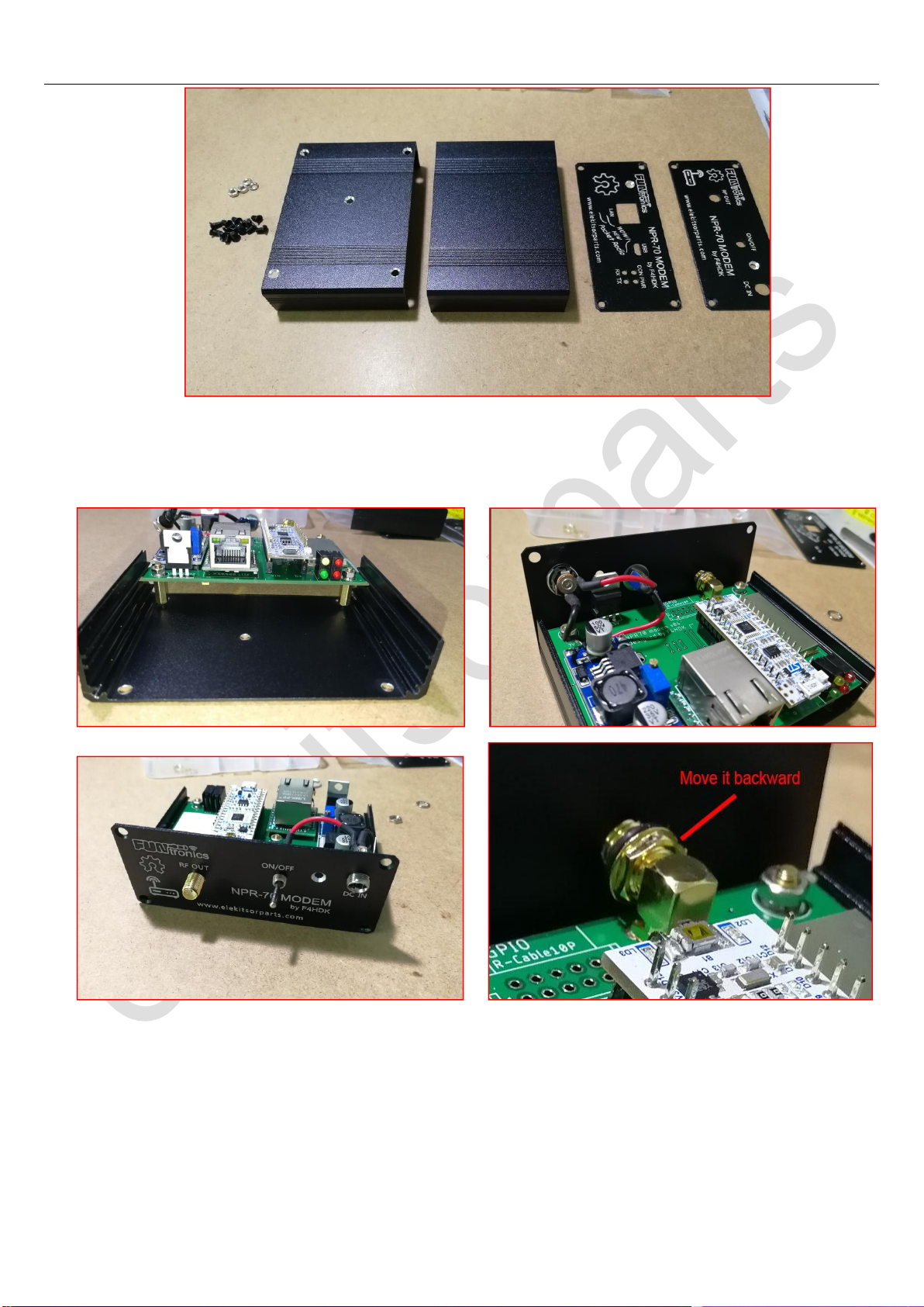
2Sequence 2
Parts Needed:Screws M3 x 6mm Black x 15, Enclosure x 1
Elekitsorparts Store Item Name: NPR-70 Modem Item No.: H10015K Document Type:Assembly Guide
15
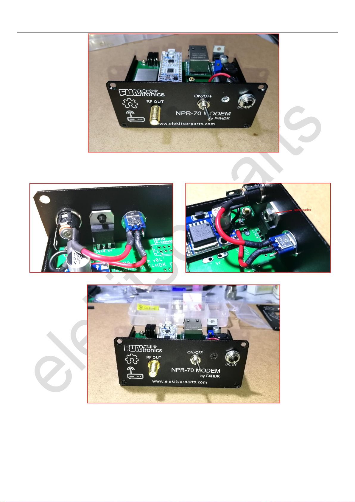
Find out supplied enclosure from the package, insert the modem board to the bottom cover of the enclosure by the slot on
the wall. Locate the rear panel, mount the DC port and toggle switch onto the panel, and finally the rear panel onto the
bottom cover. Please note that you may need to adjust the nut on the SMA port backward in order to fit our modem board
rightly inside the enclosure. See the pictures below for the details.
Elekitsorparts Store Item Name: NPR-70 Modem Item No.: H10015K Document Type:Assembly Guide
16
Next, we have to secure the L4940’s heat-sink plate onto the rear panel, also secure the SMA port with teeth washer and
nut. Now the rear panel is done. Let’s move onto the front panel.
Take out the front panel and secure it to the bottom cover, then following the instructions we just made for L4940, secure
the LM2937's heat sink plate to the front panel.

Elekitsorparts Store Item Name: NPR-70 Modem Item No.: H10015K Document Type:Assembly Guide
17
Now, turn over the modem, go to the bottom side of the enclosure, screw the 5 copper posts fixed on the main PCB board
onto the bottom cover.
Now it is almost done, locate the top cover, put the top cover on and secure it with 4 screws. Pay attention when installing
the top cover, there are groove or bump on the 2 vertical walls, and the bottom cover as well. The bump on the top should
touch the groove on the bottom cover, vice verse.

Elekitsorparts Store Item Name: NPR-70 Modem Item No.: H10015K Document Type:Assembly Guide
18
Take out the rubber feet, paste them on the bottom cover as the following picture shows.
Congratulations! You now have your own NPR-70 modem. It is time to configure your modem into “MASTER” or
“CLIENT” mode, for the detailed configuration guide, please visit F4HDK’s project page on hackaday. It is highly
recommend you to read the “Introduction and quick start guide” first of all.
After all of the configurations is done, stick the adhesive label to the top cover.
NPR-70 project page on hackaday: https://hackaday.io/project/164092
.
Table of contents


 manual")
