Elektor Fortissimo-100 Instructions for use

books
Ton Giesberts
Construction Manual
Elektor Fortissimo-100
Power Amplifier Kit
46 pages
instructions
jump
st rter
from project to product

●3
Elektor Fortissimo-100
Power Amplifier Kit
Designed by Ton Giesberts - Elektor Labs
Construction Manual
V1.0 – date: September 8, 2022,
© Elektor International Media b.v.

●5
Table of Contents
Table of Contents
Section Page
Notice
This document is complementary to the information contained in:
1. the editorial article “The Elektor Fortissimo-100 Power
Amplifier” published in Elektor Magazine edition 11&12 2022;
2. the engineering background and discussions posted on the
Elektor Labs website.
Web Links to these publications may be found in Section 22.
1 – Kit Contents 7
2 – Introduction 12
3 – Tools Needed 13
4 – Locating and Drilling Holes in the Heatsink,
for the PCB Standoffs 14
5 – Bending the Output Stage Transistor Leads 16
6 – Locating and Drilling Holes in the Heatsink,
for the Transistors 17
7 – Small Resistors and Diodes 19
8 – Axial Power Resistors and IC Socket 20
9 – Small Capacitors and Input Terminal Pins 20
10 – Finishing the Assembly of the Protection PCB 21
11 – Small Transistors, LEDs, Radial Power Resistors,
and Large Capacitors 22
12 – Placing the Loudspeaker-Signal Through-Contact Standoffs 23
13 – Transistors T13…T16 and the Small Heatsinks 24
14 – The Output-Stage Transistors 27
15 – Final Assembly 31
16 – Recommendations for the Enclosure 35
17 – Selecting BC546B/BC556B Transistors for Differential Pairs 36
18 – The SMPS800RE Power Supply 37
19 – Bill of Materials 39
20 – Specifications 43
21 – DC Voltages 45
22 – Web Links 45
23 – Schematics and PCB Layouts 46

Elektor Fortissimo-100 Power Amplifier Kit
●6
Disclaimer
The circuits described in the manual are for domestic and educational
use only. All drawings, photographs, PCB layouts, and article texts are
copyright Elektor International Media b.v. and may not be reproduced,
transmitted, or stored in any form in whole or in part without the
prior written consent from the Publisher. Patent protection may exist
in respect or circuits and devices described here. The Publisher does
not accept responsibility for failing to identify such patent(s) or other
protection. The Publisher also disclaims any responsibility for the safe
and proper function of reader-assembled projects based upon or from
schematics or information published in or in relation with this Manual.
Published by Elektor International Media b.v., PO Box 11,
NL-6114-JG, Susteren, The Netherlands.
www.elektor.com; www.elektormagazine.com.

●7
1 – Kit Contents
1 – Kit Contents
• Two PCBs: amplifier PCB and protection PCB.
• All parts listed in the Bill of Materials (BOM) found at the end of
this document (Section 19).
• Construction Manual – Downloadable PDF.
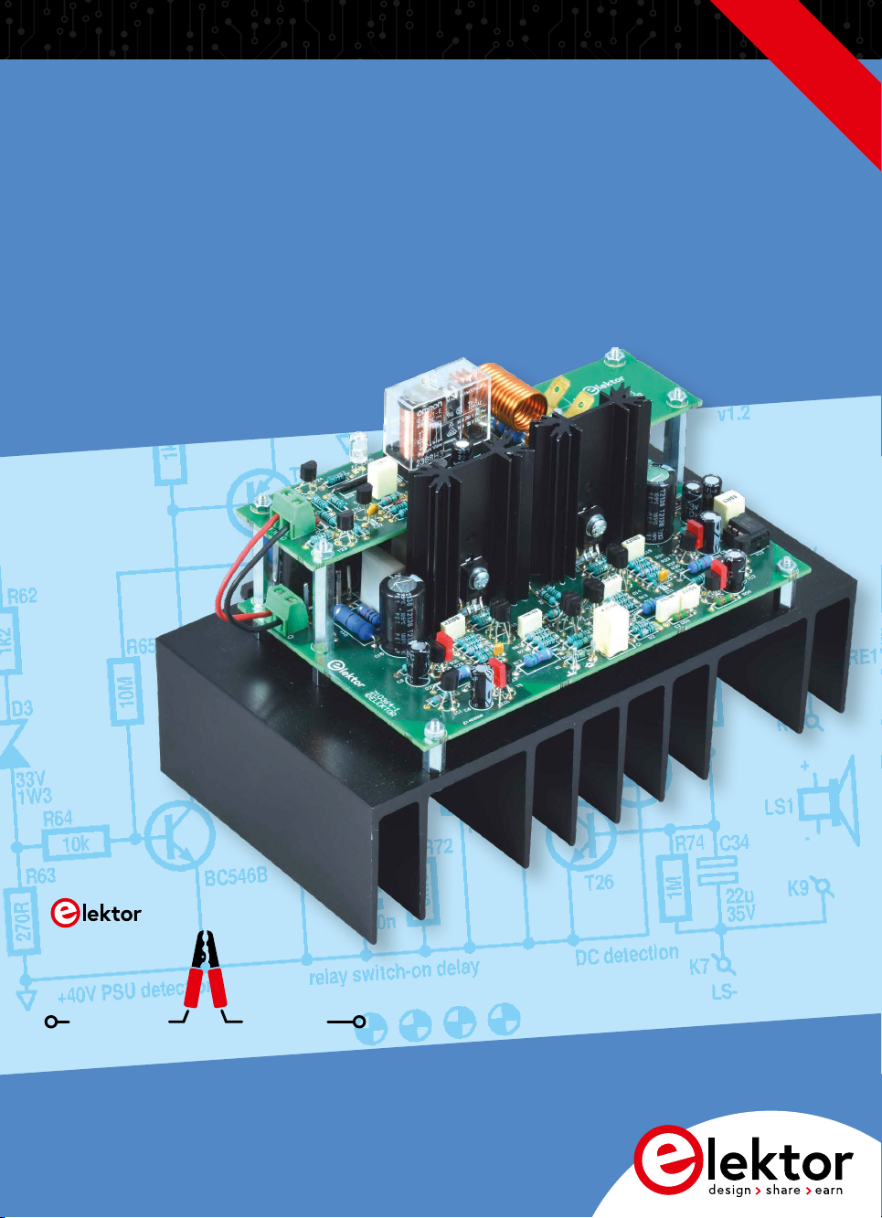
Figure 1. Contents of the Fortissimo-100 Power Amplifier kit
as supplied by the Elektor Store.
Before embarking on the construction of the Kit, be sure to inspect the
contents using the Bill of Materials and the photos that follow. Check
that all parts are supplied and in usable condition.

Elektor Fortissimo-100 Power Amplifier Kit
●8
Figure 2. The resistors and small capacitors in the kit.

●9
1 – Kit Contents
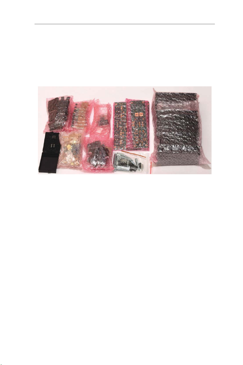
Figure 3. The electrolytic capacitors in the kit.
Figure 4. The small transistors, diodes, and other parts in the kit.

Elektor Fortissimo-100 Power Amplifier Kit
●10
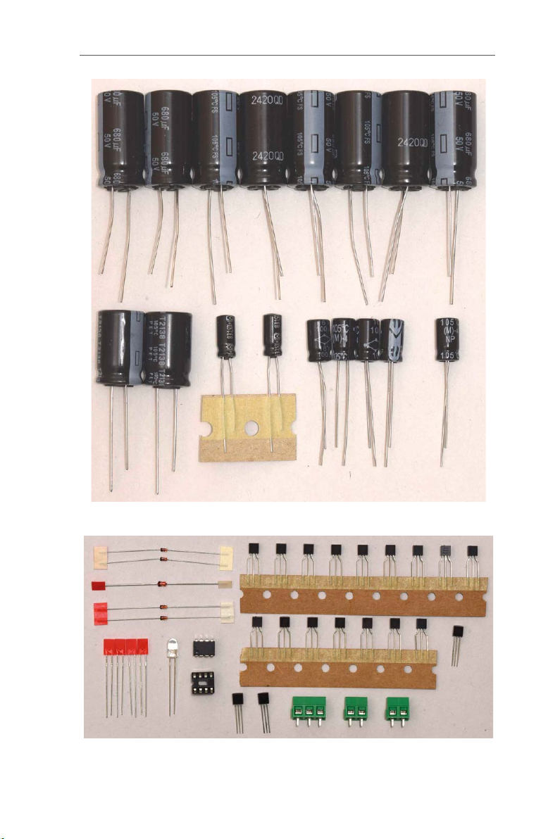
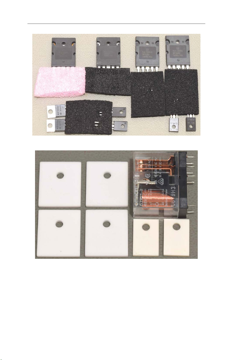
Figure 5. The larger transistors.
Figure 6. The ceramic pads (washers) and the relay in the kit.

●11
Figure 7. The mechanical parts in the kit.
Figure 8. The SK104 heatsinks in the kit.
1 – Kit Contents

Elektor Fortissimo-100 Power Amplifier Kit
●12
Figure 9. The SK53-100-SA heatsink in the kit.
2 – Introduction
Notice: It is strongly advised to closely read the entire Construction
Manual before starting the construction of the amplifier.
The design, especially the placement of the power transistors T17–T22
and the PCB, is aimed at easy replication. The mechanical work need-
ed should be possible with simple tools and basic skills like drilling 12
3-mm holes to mount the transistors and fasten the PCB in parallel
with the back of the heatsink. The fin spacing of the selected heatsink
(type SK53-100-SA from Fischer Elektronik) is sufficient for the heads
of the black 3-mm screws while also allowing room for some error.
The PCB is mounted onto the heatsink with six 10-mm long metal
male-female standoffs with 3-mm thread. The 6 transistors of the out-
put stage are electrically insulated with ceramic (Al2O3) pads, marked
by a lower thermal resistance than comparable types. During the final
stage of construction, apply some thermal grease on the back of the
transistors and on the sides of the pads placed against the heatsink.
Only a very thin layer is required! Take precautions not to get the ther-
mal grease on your fingers as most types are toxic.
The DC protection and relay circuit are placed on a second, smaller
PCB placed in parallel with the amplifier PCB. Six 30-mm long male-fe-
male metal standoffs ensure a solid construction. Standoffs K3 and K4

●13
(amplifier PCB) connect the output of the amplifier to K6 (LS+) and K7
(LS–) on the protection PCB and from there via the relay and output
terminals K8 and K9 to the loudspeaker. “Faston” connectors K8 and
K9 (PCB versions) make sure the series resistance of this connection
to the cable is extremely low.
On the finished amplifier, the screw heads should be on the back of the
heatsink. Black screws won’t stand out that much when looking at the
back of the heatsink. Black Allen-type screws are used for the tran-
sistors (with internal hexagonal recesses). Strangely enough, black
16-mm long screws are few and between at many electronic part dis-
tributors.
Selected parts shown in the photos may have different values or
shapes in your kit. This is because the amplifier shown was a first
prototype for testing.
3 – Tools Needed
• Soldering equipment for through-hole components. Soldering
iron rated at 100 watts minimum. Also recommended is an ex-
tra-long tip for soldering the transistors in the output stage.
• Small pliers with flat jaws.
• Pliers with special jaws for pressing a thermal relief (bend) in
the leads of the push-pull transistors. Alternatively: pliers with
round jaws.
• Pozidriv screwdriver (depends on the exact type of screws in the
kit).
• 2.5-mm tool for hex screws (Allen wrench; also depends on the
exact type of screws in the kit).
• Drill stands or similar tool with 3-mm drill bit to drill 12 3-mm
holes in the large heatsink. Consider using a 3.2-mm drill bit if
accuracy of drilling is sub optimal).
• 10-mm drill bit or similar rod or tube for use as a former to wind
the air inductor on.
3 – Tools Needed

Elektor Fortissimo-100 Power Amplifier Kit
●14
4 – Locating and Drilling Holes in the
Heatsink, for the PCB Standoffs
Figure 10. The bare PC boards for the amplifier and protection
circuitry, as supplied in the kit.
Figure 11. Amplifier PCB used as drilling template.

●15
The amplifier PCB is placed in the center on the heatsink, 1 mm from
the edge where C1 is located, and fixed temporarily with sellotape so
the six positions for the metal standoffs can be marked out (scored).
Use a 3.5-mm drill bit and with some pressure turn it counterclockwise
in the six holes located at the short sides of the PCB, taking great care
to avoid damage to the PCB. Do not score the positions K3 and
K4. Being the outputs of the amplifier, they must never be in electrical
contact with the heatsink! All six holes are located at ample distances
from the heatsink fins to allow room for the screw heads including a
small error margin.
Figure 12. Standoffs secured in place for the PCB to be mounted.
After the six 3-mm holes are drilled, the six 10-mm standoffs are
mounted on the heatsink and fastened with the black 12-mm M3
screws. Next, check if the PCB fits accurately on the six standoffs. If
not, consider filing out one or more holes to slightly correct the position
of the standoff(s).
4 – Locating and Drilling Holes in the Heatsink, for the PCB Standoffs

Elektor Fortissimo-100 Power Amplifier Kit
●16
5 – Bending the Output Stage Transistor
Leads
Figure 13. Bent leads of the TO-220 and TO-264
transistors in the output stage.
Bend all leads of the transistors (T17–T22) perpendicular toward the
front of the transistors (Figure 13). To avoid excessive force exerted
from the leads to the package of the large power transistors, use a
2-mm drill bit and a small vice. Gently clamp the pins and the drill bit
between the vice jaws. Use a flat piece of material to bend all leads
toward the front of the transistor. Bending the leads of the smaller
TO-220 packages can be done with flat-jaw pliers. Bend them at 1 mm
from the package, where the leads become smaller.

6 – Locating and Drilling Holes in the Heatsink, for the Transistors
●17
6 – Locating and Drilling Holes in the
Heatsink, for the Transistors
Figure 14. Preparations for marking the 3-mm holes
required for the transistors.
Before mounting any parts on the PCB, locate the position of the holes
for the six screws to secure the transistors to the heatsink. Figure 14
shows the PCB with the 6 power stage transistors temporarily fitted
(i.e., not soldered) to permit marking out the positions of the six 3-mm
holes. Also, the ceramic insulation pads must be placed between the
transistors and the heatsink since this can affect the exact position of
the holes. In this prototype, the four holes for the power transistors are
approximately 8.8 mm from the edge of the heatsink, and the smaller
transistors, at 11.5 mm. However, this can vary, and the exact location
depends on the exact position of the bend in the transistor leads. It’s
unlikely that a drilling reference for the heatsink indicates the correct
positions of the transistors. Mark (score) the six holes using a 3-mm
drill bit. Using your fingers and with some force, turn the bit counter-
clockwise through the aligned holes in the transistors and pads.

Elektor Fortissimo-100 Power Amplifier Kit
●18
Figure 15. Marked-out positions for the
six holes to be drilled (prototype).
Figure 16. Six 3-mm holes drilled for the
transistors in the output stage.
After drilling the holes, place the transistors in position with their
screws. It’s not necessary to secure them with nuts. Check if the PCB
is a perfect fit with all leads and the six standoffs through their holes.

7 – Small Resistors and Diodes
●19
Now almost all parts can be fitted on the PCBs. Start with the lowest
components, small resistors and diodes (D1…D5).
7 – Small Resistors and Diodes
Figure 17. The small resistors and diodes
soldered onto the two boards.

Elektor Fortissimo-100 Power Amplifier Kit
●20
8 – Axial Power Resistors and IC Socket
Figure 18. Axial power resistors and 8-pin IC socket (pos. IC3)
soldered onto the amp board.
9 – Small Capacitors and Input Terminal
Pins
Figure 19. The small capacitors also soldered
onto the amplifier board.

10 – Finishing the Assembly of the Protection PCB
●21
Place and solder the small capacitors, the smallest ones first: C3, C10,
C11, C32, C4, C5, C12, C2, C13, C14, C18, C19, C29, C17, C33, C28.
Next, the larger/higher-value capacitors: C6, C7, C8, C9, C30, C31,
C34 , input terminal pins, C1.
10 – Finishing the Assembly of the
Protection PCB
Figure 20. To finish the protection board, solder the
relay and the air-cored inductor onto the board.
Figure 21. The completed protection board
(PCB 210364-1 v1.1 shown).
Table of contents
Popular Amplifier manuals by other brands

Harman
Harman JBL SYNTHESIS SDA8300 Quick start installation guide

Precision Power
Precision Power PowerClass PC4200 owner's manual

Soundstream
Soundstream D'Artagnan5.1 Owner's manual and installation guide

Vintage Vibe
Vintage Vibe Wurly 200A Installation

Arcam
Arcam SA30 Service manual

Rotel
Rotel RMB-1076 Technical manual