Sony XM-GTR2202 User manual

SERVICE MANUAL
Sony Corporation
Published by Sony Techno Create Corporation
XM-GTR2202
STEREO POWER AMPLIFIER
9-889-724-02
2011H33-1
© 2011.08
US Model
Canadian Model
AEP Model
UK Model
E Model
Ver. 1.1 2011.08
SPECIFICATIONS
AUDIO POWER SPECIFICATIONS
POWER OUTPUT AND TOTAL HARMONIC DISTORTION
220 watts per channel minimum continuous average power into 4 ohms,
both channels driven from 20 Hz to 20 kHz with no more than 1% total
harmonic distortion per Car Audio Ad Hoc Committee standards.
Other Specifications
Circuit system OTL (output transformerless) circuit
Pulse power supply
Inputs RCA pin jacks
High level input connector
Outputs Speaker terminals
Through out pin jacks
Suitable speaker impedance
2 8 (stereo)
4 8 (when used as a bridging amplifier)
Maximum outputs 440 W 2 (at 4 )
650 W 2 (at 2 )
1,400 W (BTL) (at 4 )
Rated output (supply voltage at 14.4 V, 20 Hz 20 kHz, 1% THD + N)
220 W 2 (at 4 )
270 W 2 (at 2 )
540 W (BTL) (at 4 )
Frequency response 10 Hz 50 kHz (–3 dB)
Input level adjustment range
0.3 6.0 V (RCA pin jacks)
1.2 12.0 V (High level input)
Low-pass filter 50 Hz 300 Hz, 12 dB/oct
Subsonic filter 6 Hz 70 Hz, 12 dB/oct
Low boost 0 10 dB (40 Hz)
Power requirements 12 V DC car battery (negative ground)
Power supply voltage
10.5 16 V
Current drain at rated output: 50 A (at 4 )
Remote input: 1 mA
Dimensions Approx. 424 55 280 mm
(16
3/4 2 1/4 11 1/8 in) (w/h/d) not incl.
projecting parts and controls
Mass Approx. 3.6 kg (7 lb 15 oz) not incl. accessories
Supplied accessories
Mounting screws (4)
High level input cord (1)
Protection cap (1)
Design and specifications are subject to change without notice.
+0
Dimensions / Dimensions / Dimensiones
Unit: mm (in)
Unité : mm (po)
Unidad: mm
ø 6 (1/4)
264 (10
1/2)
424 (16
3/4)
354 (14)
55
(2 1/4)
354 (14)
280 (11
1/8)
jomi

XM-GTR2202
2
PROTECTOR OPERATION CHECK
Thermal Protect
1. Short across TH301 (short between TP19 and TP20) and turn the
power on.
2. Verify that the protector is operated with D904 illuminated green.
At this time, the output on the SP-OUT is reduced to 1/5, sound
comes out from the speaker and the volume control is also operative.
3. Remove the short given in item 1. Verify that the protector is released
and the output on the SP-OUT is restored to the original level.
4. Likewise, perform items 1 to 3 for TH302 (short between TP19 and
TP21) and TH303 (short between TP19 and TP22). Note that for
TH302 and TH303, no sound comes out from the speaker and the
volume control is inoperative.
Over Current Protect
1. Short between the positive and negative sides of the speaker output
terminal TB901 (1/3),(2/3) with the power on.
2. Verify that the protector is operated and D904 illuminates red.
3. Verify that the protector is not released and D904 remains red even
when the short is removed.
4. Verify that the protector is released and D904 illuminates green
when the power is turned off and then on again.
Offset Protect
1. Short between the +12V terminal of TB901 (3/3) and the BTL +
or BTL of the speaker output terminal TB901 (1/3),(2/3).
(Short between +12V terminal and BTL + and between +12V
terminal and BTL .)
2. Verify that the protector is operated and D904 illuminates red.
3. Verify that the protector is not released and D904 remains red even
when the short is removed.
4. Verify that the protector is released and D904 illuminates green
when the power is turned off and then on again.
UNLEADED SOLDER
Boards requiring use of unleaded solder are printed with the lead-free
mark (LF) indicating the solder contains no lead.
(Caution: Some printed circuit boards may not come printed with the
lead free mark due to their particular size)
: LEAD FREE MARK
Unleaded solder has the following characteristics.
• Unleaded solder melts at a temperature about 40 °C higher than
ordinary solder.
Ordinary soldering irons can be used but the iron tip has to be applied
to the solder joint for a slightly longer time.
Soldering irons using a temperature regulator should be set to
about 350 °C.
Caution: The printed pattern (copper foil) may peel away if the
heated tip is applied for too long, so be careful!
• Strong viscosity
Unleaded solder is more viscous (sticky, less prone to flow) than
ordinary solder so use caution not to let solder bridges occur such as
on IC pins, etc.
• Usable with ordinary solder
It is best to use only unleaded solder but unleaded solder may also be
added to ordinary solder.
NOTES ON CHIP COMPONENT REPLACEMENT
• Never reuse a disconnected chip component.
• Notice that the minus side of a tantalum capacitor may be damaged
by heat.
1. GENERAL
Connections .................................................................... 3
2. DISASSEMBLY
2-1. Bottom Plate ................................................................... 7
2-2. MAIN Board Section...................................................... 8
2-3. LED1 Board, LED2 Board ............................................. 8
2-4. MAIN Board................................................................... 9
3. DIAGRAMS
3-1. Block Diagram................................................................ 11
3-2. Printed Wiring Boards .................................................... 12
3-3. Schematic Diagram (1/2)................................................ 13
3-4. Schematic Diagram (2/2)................................................ 14
4. EXPLODED VIEWS
4-1. Heat Sink (Main) Section ............................................... 15
4-2. Main Board Section ........................................................ 16
5. ELECTRICAL PARTS LIST.................................. 17
TABLE OF CONTENTS
SAFETY-RELATED COMPONENT WARNING!
COMPONENTS IDENTIFIED BY MARK 0OR DOTTED LINE
WITH MARK 0ON THE SCHEMATIC DIAGRAMS AND IN
THE PARTS LIST ARE CRITICAL TO SAFE OPERATION.
REPLACE THESE COMPONENTS WITH SONY PARTS
WHOSE PART NUMBERS APPEAR AS SHOWN IN THIS
MANUAL OR IN SUPPLEMENTS PUBLISHED BY SONY.
ATTENTION AU COMPOSANT AYANT RAPPORT
À LA SÉCURITÉ!
LES COMPOSANTS IDENTIFIÉS PAR UNE MARQUE 0SUR
LES DIAGRAMMES SCHÉMATIQUES ET LA LISTE DES
PIÈCES SONT CRITIQUES POUR LA SÉCURITÉ DE FONC-
TIONNEMENT. NE REMPLACER CES COMPOSANTS QUE
PAR DES PIÈCES SONY DONT LES NUMÉROS SONT DON-
NÉS DANS CE MANUEL OU DANS LES SUPPLÉMENTS
PUBLIÉS PAR SONY.
jomi

XM-GTR2202
3
SECTION 1
GENERAL This section is extracted
from instruction manual.
Power Connection Wires (not supplied)
Câbles d’alimentation (non fournis)
Cables de conexión de alimentación (no suministrados)
Connections/Connexions/Conexiones
Cautions
Before making any connections, disconnect the ground
terminal of the car battery to avoid short circuits.
Be sure to use speakers with an adequate power rating. If you
use small capacity speakers, they may be damaged.
Do not connect the #terminal of the speaker system to the
car chassis, and do not connect the # terminal of the right
speaker with that of the left speaker.
This is a phase-inverted Amplifier.
Install the input and output cords away from the power
supply wire as running them close together can generate
some interference noise.
This unit is a high powered amplifier. Therefore, it may not
perform to its full potential if used with the speaker cords
supplied with the car.
If your car is equipped with a computer system for
navigation or some other purpose, do not remove the
ground wire from the car battery. If you disconnect the wire,
the computer memory may be erased. To avoid short circuits
when making connections, disconnect the +12 V power
supply wire until all the other wires have been connected.
This unit is equipped with cooling fan. Do not block the
ventilation hole*.
Connect the +12 V power supply wire only after all the other
wires have been connected.
.
..
.
.
.
.
.
.
.
.
.
.
.
.
Be sure to connect the ground wire of the unit securely to a
metal point of the car. A loose connection may cause a
malfunction of the amplifier.
Be sure to connect the remote control wire of the car audio
unit to the remote terminal.
When using a car audio unit without a remote output on the
amplifier, connect the remote input terminal (REMOTE) to the
accessory power supply.
Use a power supply wire with a fuse attached (80 A).
All power wires connected to the positive battery post should
be fused within 450 mm (18 in) of the battery post, and
before they pass through any metal.
Make sure that the vehicle’s battery wires connected to the
vehicle are of a wire gauge at least equal to that of the main
power wire connected from the battery to the amplifier.
During full-power operation,a current of more than 80 A will
run through the system. Therefore, make sure that the wires
to be connected to the +12 V and GND terminals of this unit
are at least 8-Gauge (AWG-8) or have asectional area of more
than 8 mm 2(11/32 in2).
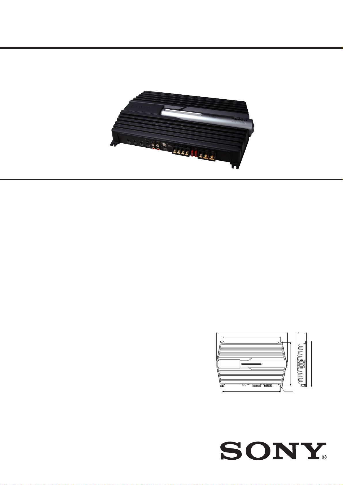
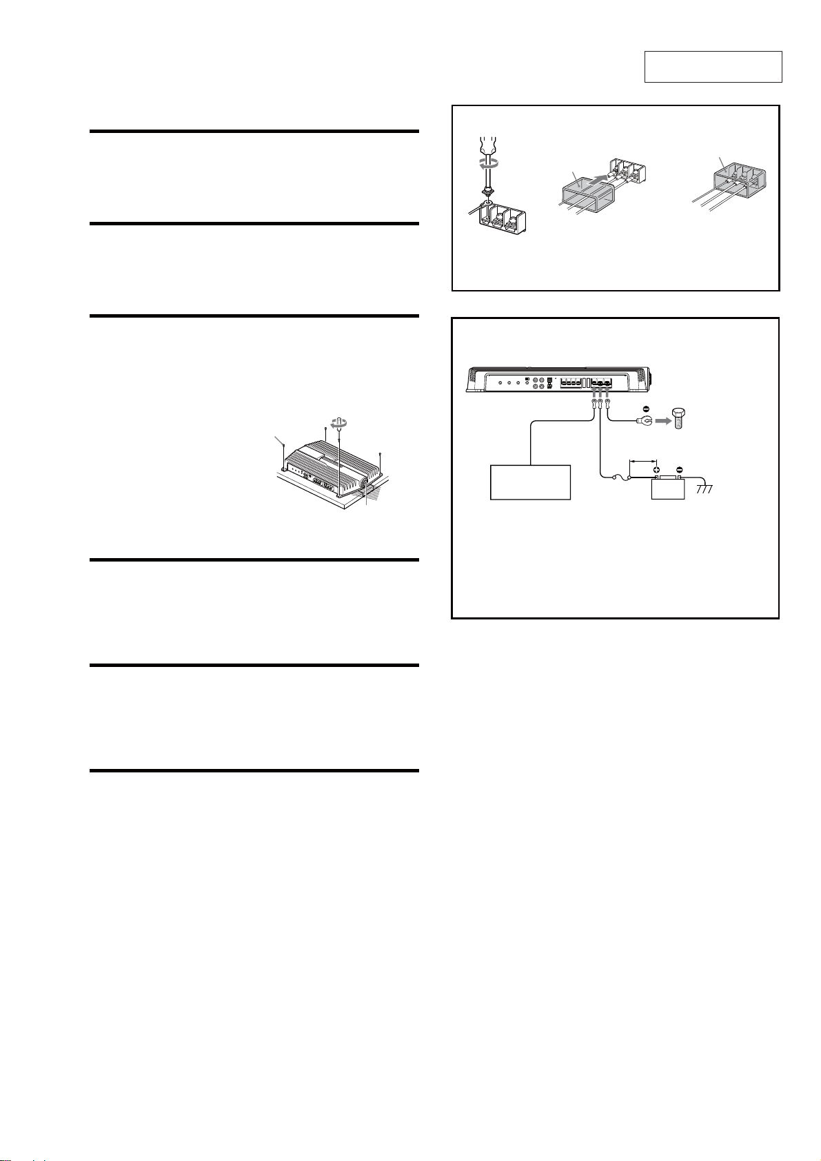
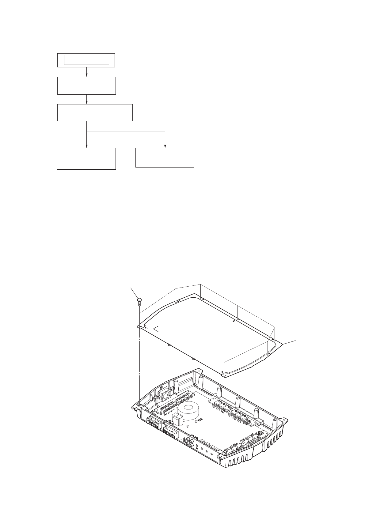
Mount the unit as illustrated.
Montez l’appareil comme illustré.
Monte la unidad tal como se muestra en la
ilustración.
Installation
Before Installation
Mount the unit either inside the trunk or under a seat.
Choose the mounting location carefully so the unit will not
interfere with the normal movements of the driver and it will
not be exposed to direct sunlight or hot air from the heater.
Do not install the unit under the floor carpet, where the heat
dissipation from the unit will be considerably impaired.
First, place the unit where you plan to install it, and mark the
positions of the four screw holes on the surface of the
mounting board (not supplied). Then drill the holes
approximately 3 mm (1/8in) in diameter and mount the unit
onto the board with the supplied mounting screws. The
supplied mounting screws are 15 mm (19/32 in) long. Therefore,
make sure that the mounting board is thicker than 15 mm
(19/32 in).
*1If you have the factory original or some
other car audio unit without a remote
output for the amplifier, connect the
remote input terminal (REMOTE) to the
accessory power supply.
In High level input connection, car audio
unit can also be activated without need for
REMOTE connection. However, this
function is not guaranteed for all car audio
units.
*2Ground to chassis
*1Si vous disposez du modèle d’origine ou
d’un autre autoradio dont l’amplificateur
ne comporte pas de sortie de
télécommande, raccordez la borne
d’entrée de télécommande (REMOTE) à la
prise d’alimentation accessoires.
Dans une connexion d’entrée à haut
niveau, l’autoradio peut également être
activé sans raccordement à REMOTE.
Toutefois, cette fonction n’est pas garantie
pour tous les autoradios.
*2Masse au châssis
*1Si dispone del sistema de audio para
automóvil original de fábrica o de otro
sistema sin una salida remota en el
amplificador, conecte el terminal de
entrada remota (REMOTE) al suministro de
alimentación auxiliar.
En la conexión de entrada de alto nivel, la
unidad de audio del vehículo también
puede activarse sin necesidad de conexión
REMOTE. No obstante, esta función no se
garantiza en todas las unidades de
automóvil.
*2A la masa del chasis
Installation
Avant l’installation
.Installez l’appareil dans le coffre ou sous un siège.
.
.
Choisissez un endroit de montage judicieux pour que
l’appareil ne gêne pas les mouvements naturels du
conducteur et pour qu’il ne soit pas exposé aux rayons
directs du soleil ou à proximité d’une bouche d’air chaud.
.
.
.
..
.
.
.
.
.
.
..
.
.
.
.
.
.
..
.
.
.
.
.
.
N’installez pas l’appareil sous le tapis, car cela empêcherait
l’évacuation de la chaleur de l’appareil.
Tout d’abord, mettez l’appareil où vous prévoyez de l’installer
et tracez les quatre trous de vis sur la surface de la plaque de
montage (non fournie). Percez ensuite les trous selon un
diamètre d’environ 3 mm (1/8po) et installez l’appareil sur la
plaque avec les vis de montage fournies. Les vis de montage
fournies font 15 mm (19/32 po) de long. Par conséquent,
assurez-vous que la plaque de montage fait plus de 15 mm
(19/32 po) d’épaisseur.
Attention
Avant d’effectuer les connexions, débranchez la borne de
masse de la batterie de voiture pour éviter tout court-circuit.
Veillez à utiliser des haut-parleurs de puissance adéquate. Si
vous utilisez des haut-parleurs de faible capacité, ils risquent
d’être endommagés.
Ne raccordez pas la borne #du système de haut-parleurs à
la carrosserie de la voiture ou la borne#du haut-parleur
droit à celle du haut-parleur gauche.
Les phases de cet amplificateur sont inversées.
Éloignez les câbles d’entrée et de sortie du câble
d’alimentation pour éviter les interférences.
Cet appareil est un amplificateur de haute puissance. Il ne
peut donc déployer sa pleine puissance que si les câbles de
haut-parleurs de la voiture lui sont raccordés.
Si votre voiture est équipée d’un système de navigation ou
d’un ordinateur de bord, ne retirez pas le fil de masse de la
batterie de la voiture, sinon les données mémorisées seront
effacées. Pour éviter un court-circuit lorsque vous effectuez
les branchements, branchez le câble d’alimentation +12 V
après avoir branché tous les autres fils.
Cet appareil est équipé d’un ventilateur de refroidissement.
Ne bloquez pas l’orifice de ventilation*.
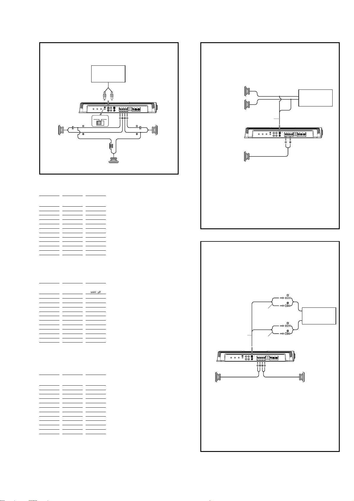
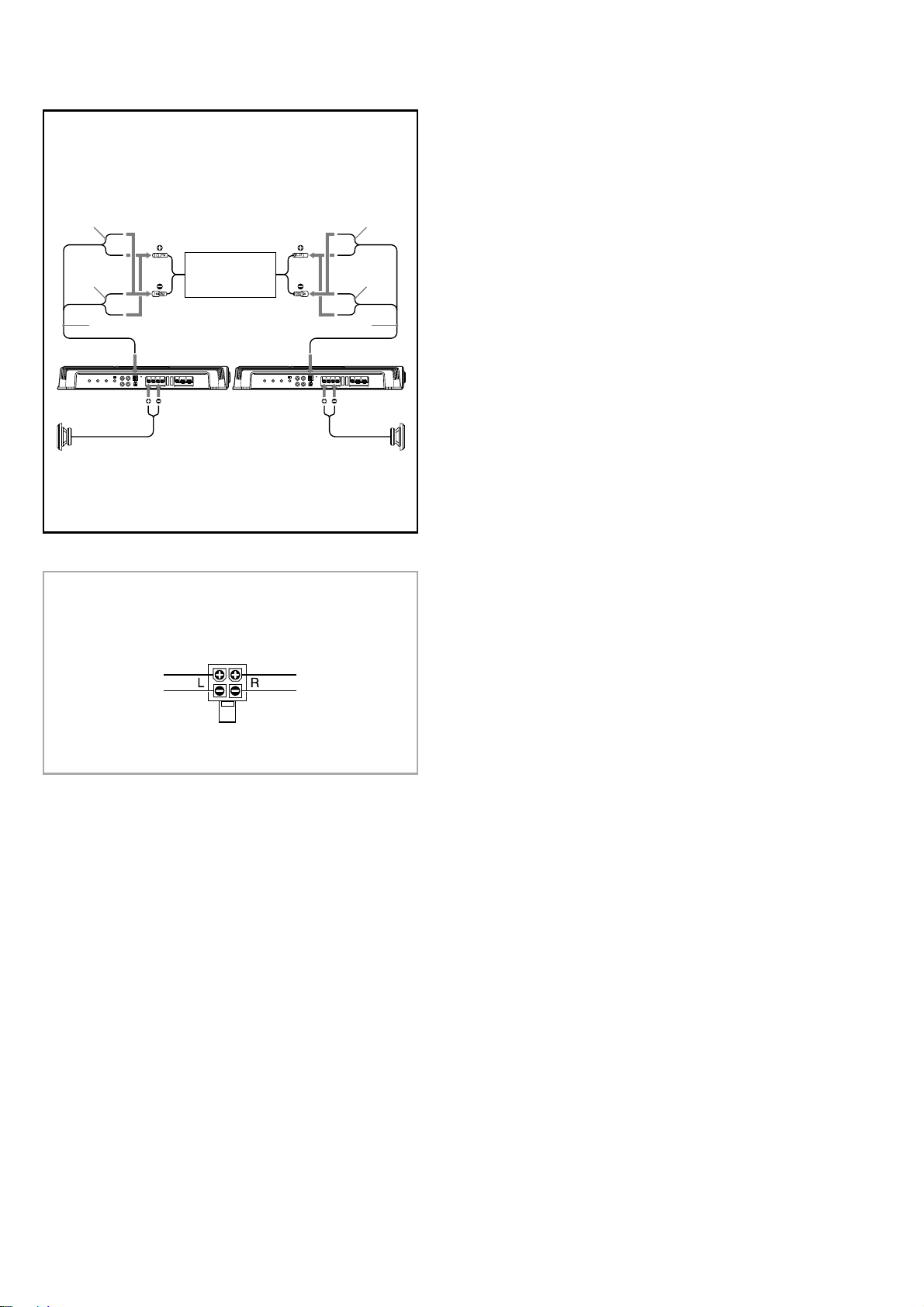
Make the terminal connections as illustrated below.
Procédez aux connexions des bornes comme illustré ci-dessous.
Realice las conexiones de terminal como se ilustra a continuación.
Pass the wires through the cap,
connect the wires, then cover the
terminals with the cap.
Note
When you tighten the screw, be careful not to
apply too much torque*as doing so may
damage the screw.
*The torque value should bHOHVVWKDQ1P
Faites passer les câbles par le cache,
raccordez les câbles, puis recouvrez
les bornes avec le cache.
Remarque
Lorsque vous vissez la vis, faites attention à
ne pas appliquer une trop grande force*, car
cela pourrait endommager la vis.
* Le couple de torsion doit être inférieur à
11P
Pase los cables a través de la cubierta,
conéctelos y cubra los terminales con
dicha cubierta.
Nota
Al apretar el tornillo, tenga cuidado de no
aplicar demasiada fuerza de torsión*, ya que
puede dañarlo.
*El valor de fuerza de torsión debe ser
LQIHULRUD1P
REM
+
12V GND
3
REM
+
12V GND
3
,
to a metal point of the car
versune partie métallique de la carrosserie
a un punto metálico del automóvil
+12 V car battery
Batterie de voiture +12 V
Batería de automóvil de +12 V
Car audio unit
Autoradio
Sistema de audio para
automóvil
Remote output*1
Sortie de
télécommande*1
(REM OUT)
Salida remota*1
(REM OUT) less than 450 mm (18 in)
moins de 450 mm (18 po)
menos de 450 mm
*2
Fuse (80 A)
Fusible (80 A)
Fusible (80 A)
Remarques
Notes on the power supply
sur l’alimentation électrique
Raccordez le câble d’alimentation +12 V uniquement après
avoir réalisé toutes les autres connexions.
Raccordez correctement le fil de masse à une partie
métallique de la voiture. Une connexion lâche peut
provoquer un problème de fonctionnement de
l’amplificateur.
Veillez à raccorder le fil de télécommande de l’autoradio à la
borne de télécommande.
Si vous utilisez un autoradio dont l’amplificateur ne
comporte pas de sortie de télécommande, raccordez la borne
d’entrée de la télécommande (REMOTE) à la prise
d’alimentation accessoires.
Utilisez un câble d’alimentation muni d’un fusible (80 A).
Tous les fils électriques raccordés au support de batterie
positif doivent être protégés par un fusible à une distance
maximum de 450 mm (18 po) du support de batterie et avant
de passer dans une partie métallique quelconque.
Assurez-vous que les fils de la batterie du véhicule raccordés à
ce dernier sont d’un calibre au moins égal à celui du fil
électrique principal reliant la batterie et l’amplificateur.
Pendant une utilisation à pleine puissance, un courant d’une
intensité supérieure à 80 A circule dans le système. Assurez-
vous que les câbles à raccorder aux bornes +12 V et GND de
cet appareil sont de calibre supérieur à 8 (AWG-8) ou d’une
section supérieure à 8 mm 2
( 11/32 po2).
Notas sobre la fuente de alimentación
Conecte el cable de la fuente de alimentación de +12 V sólo
después de haber conectado los otros cables.
Asegúresede conectar firmemente el cable de toma a
tierra de la unidad a un punto metálico del automóvil. Una
conexión incorrecta puede causar fallos de
funcionamiento del amplificador.
Compruebe que conecta el cable de control remoto del
sistema de audio para automóvil al terminal remoto.
Si utiliza un sistema de audio para automóvil sin salida
remota en el amplificador, conecte el terminal de entrada
remota (REMOTE) a la fuente de alimentación auxiliar.
Emplee el cable de la fuente de alimentación con un fusible
fijado (80 A).
Todos los cables de alimentación conectados al polo positivo
de la batería deben conectarse a un fusible situado a menos
de 450 mm del polo de la batería, y antes de pasar por
ninguna pieza metálica.
Asegúrese de que los cables de la batería del vehículo
conectados al mismo tienen una anchura igual o superior a
la del cable de alimentación principal que conecta la batería
con el amplificador.
Durante el funcionamiento a pleno rendimiento, fluye por el
sistema una corriente superior a 80 A. Por tanto, compruebe
que los cables que va a conectar a los terminales de +12 V y
GND de esta unidad son del calibre 8 (AWG 8) como mínimo
o presentan un área de sección superior a 8 mm 2.
Instalación
Antes de realizar la instalación
Monte la unidad en el interior del maletero o debajo de un
asiento.
Elija cuidadosamente el lugar de instalación de forma que la
unidad no dificulte los movimientos normales del conductor
y no quede expuesta a la luz solar directa ni al aire caliente
de la calefacción.
No instale la unidad debajo de la moqueta del suelo, en cuyo
caso la disipación de calor de la misma disminuirá
considerablemente.
En primer lugar, coloque la unidad donde tenga previsto
instalarla y marque sobre la superficie del tablero de montaje
(no suministrado) las posiciones de los cuatro orificios para
los tornillos. A continuación, perfore los orificios con un
diámetro de aproximadamente 3 mm y monte la unidad sobre
el tablero con los tornillos de montaje suministrados.
Compruebe que el grosor del tablero de montaje sea superior a
15 mm, ya que la longitud de estos tornillos es de 15 mm.
Precauciones
Antes de realizar las conexiones, desconecte el terminal de toma
a tierra de la batería del automóvil para evitar cortocircuitos.
Asegúrese de utilizar altavoces con una potencia nominal
adecuada. Si emplea altavoces de capacidad reducida,
pueden dañarse.
No conecte el terminal del sistema de altavoces al chasis
del automóvil, ni el terminal #
#
del altavoz derecho al del
altavoz izquierdo.
Este amplificador es de fase invertida.
Instale los cables de entrada y salida alejados del cable de la
fuente de alimentación, ya que en caso contrario puede
generarse ruido por interferencias.
Esta unidad es un amplificador de alta potencia. Por tanto,
puede no funcionar a pleno rendimiento si se utiliza con los
cables de altavoz suministrados con el automóvil.
Si el automóvil está equipado con un sistema de ordenador
para la navegación o para otra finalidad, no desconecte el
conductor de toma a tierra de la batería del automóvil. Si lo
desconecta, la memoria del ordenador puede borrarse. Para
evitar cortocircuitos al realizar las conexiones, desconecte el
cable de la fuente de alimentación de +12 V hasta conectar
todos los cables.
La unidad dispone de un ventilador de refrigeración. No
obstruya el orificio de ventilación*.
1
Ventilation hole*
Orifice de ventilation*
Orificio de ventilación*
*
.
.
.
.
.
.
.
..
.
.
.
.
jomi

XM-GTR2202
4
2-Speaker System
Système à 2 haut-parleurs
Sistema de 2 altavoces
Caraudio unit
Autoradio
Sistemade audio para
automóvil
For details on the settings of switches and
controls, refer to“Location and Function of
Controls.”
Pour plus de détails sur les réglages des
commutateurs et commandes, reportez-vous à
« Emplacement et fonction des commandes ».
Para obtener más información sobre los ajustes
de los interruptores y controles, consulte
“Ubicación y función de los controles
”.
Left speaker
minȍ
Haut-parleur gauche
minȍ
Altavoz izquierdo
mtnȍ
Right speaker
minȍ
Haut-parleur droit
minȍ
Altavoz derecho
mtnȍ
As a Monaural Amplifier
Comme amplificateur monaural
Como amplificador monoaural
BTLBTL
BTLBTL
Caraudio unit
Autoradio
Sistemade audio para
automóvil
For details on the settings of switches
and controls, refer to“Location and
Function of Controls.”
Note
Make sure that the line output from
the car audio unit is connected to the
jack marked“L (BTL)”on the unit.
Pour plus de détails sur les réglages
des commutateurs et commandes,
reportez-vous à « Emplacement et
fonction des commandes ».
Remarque
Vérifiez que la sortie de ligne de
l’autoradio est raccordée à la prise
portant l’indication « L (BTL) » sur
l’appareil.
Para obtener más información sobre
los ajustes de los interruptores y
controles, consulte“Ubicación y
función de los controles”.
Nota
Compruebe que la salida de línea del
sistema de audio para automóvil está
conectada a la toma con la marca“L
(BTL)”de la unidad.
Right channel
Canal droit
Canal derecho
Left channel
Canal gauche
Canal izquierdo
Left speaker minȍ
Haut-parleur gauche
minȍ
Altavoz izquierdo mtnȍ
Right speaker
minȍ
Haut-parleur droit
minȍ
Altavoz derecho
mtnȍ
2-way System
Système 2 voies
Sistema de 2 vías
Two output channels
Deux canaux de sortie
Dos canales de salida
OFF FILTER OFF FILTER
Caraudio unit
Autoradio
Sistemade audio para
automóvil
Use the THROUGH OUT terminal when
you install more amplifiers.
The signals are output as they were
input. (LOW BOOST, LP, HP do not
work.)
Notes
A maximum 3 amplifiers can be
connected to the THROUGH OUT
terminal. If you connect more than
three amplifiers, it may cause
problems such as sound dropout.
High level input connection cannot
use THROUGH OUT.
Utilisez la borne THROUGH OUT
lorsque vous installez plusieurs
amplificateurs.
Les signaux sont émis tels qu’ils sont
reçus. (LOW BOOST, LP, HP ne
fonctionnent pas.)
Remarques
Vous pouvez raccorder un maximum
de 3 amplificateurs à la borne
THROUGH OUT. Si vous raccordez
plus de trois amplificateurs, cela
peut provoquer des problèmes
comme des baisses du son.
Avec une connexion d’entrée de haut
niveau, vous ne pouvez pas utiliser
THROUGH OUT.
Si instala varios amplificadores, utilice
el terminal THROUGH OUT.
Las señales se emitirán del mismo
modo en que se recibieron. (LOW
BOOST y LP, HP no funcionan).
Notas
Se puede conectar un máximo de 3
amplificadores al terminal
THROUGH OUT. Si conecta más de
tres, pueden producirse problemas,
como interrupciones del sonido.
Una conexión de entrada de nivel
alto no puede utilizar THROUGH
OUT.
Full range speakers minȍ
Haut-parleurs à gamme étendue
minȍ
Altavoces de gama completa
mtnȍ
Subwoofers minȍ
Haut-parleurs d’extrêmes graves
minȍ
Altavoces potenciadores de graves
mtnȍ
LINE OUT
LINE OUT
As the Monaural Amplifier for a Subwoofer
Comme amplificateur monaural pour un haut-parleur
d’extrêmes graves
Como amplificador monoaural para un altavoz potenciador de
graves
OFF FILTER
BTLBTL
Caraudio unit
Autoradio
Sistemade audio para
automóvil
For details on the settings of switches
and controls, refer to“Location and
Function of Controls.”
Note
If you wish to use a subwoofer as a
monaural speaker, connect the
speaker as illustrated above. The
output signals to the subwoofer will be
the combination of the both right and
left output signals.
Pour plus de détails sur les réglages
des commutateurs et commandes,
reportez-vous à « Emplacement et
fonction des commandes ».
Remarque
Si vous désirez utiliser un haut-parleur
d’extrêmes graves comme haut-
parleur monaural, raccordez le haut-
parleur comme illustré ci-dessus. Les
signaux de sortie vers le haut-parleur
d’extrêmes graves seront une
combinaison des signaux de sortie
droit et gauche.
Para obtener más información sobre
los ajustes de los interruptores y
controles, consulte“Ubicación y
función de los controles”.
Nota
Si desea utilizar un altavoz
potenciador de graves como altavoz
monoaural, conecte el altavoz tal
como se muestra en la ilustración. Las
señales que se emitan hacia el altavoz
potenciador de graves serán una
combinación de las señales de salida
derecha e izquierda.
Subwoofer minȍ
Haut-parleur d’extrêmes graves
minȍ
Altavoz potenciador de graves
mtnȍ
LINE OUT
LINE OUT
INPUT THROUGH OUT INPUT
2-way System
Système 2 voies
Sistema de 2 vías
Four output channels
Quatre canaux de sortie
Cuatro canales de salida
OFF FILTER OFF FILTER
Caraudio unit
Autoradio
Sistemade audio para
automóvil
Full range speakers minȍ
Haut-parleurs à gamme étendue minȍ
Altavoces de gama completa mtnȍ
Subwoofers minȍ
Haut-parleurs d’extrêmes graves
minȍ
Altavoces potenciadores de graves
mtnȍ
For details on the settings of switches
and controls, refer to“Location and
Function of Controls.”
Note
In this system, the volume of the
subwoofers will be controlled by the
car audio fader control.
Pour plus de détails sur les réglages
des commutateurs et commandes,
reportez-vous à « Emplacement et
fonction des commandes ».
Remarque
Dans ce système, le volume des haut-
parleurs d’extrêmes graves est contrôlé
par la commande de balance avant/
arrière de l’autoradio.
Para obtener más información sobre
los ajustes de los interruptores y
controles, consulte“Ubicación y
función de los controles”.
Nota
En este sistema, el volumen de los
altavoces potenciadores de graves se
controla mediante el control de
equilibrio entre altavoces del sistema
de audio para automóvil.
LINE OUT
..
.
.
.
.
.
.
.
.
jomi

XM-GTR2202
5
Dual Mode System(With a Bridged Subwoofer)
Double mode de connexion
(avec un haut-parleur d’extrêmes graves en pont)
Sistema de modo dual (con un altavoz potenciador de graves en puente)
OFF FILTER
Caraudio unit
Autoradio
Sistemade audio para
automóvil
For details on the values of C1, C2, L, refer to“Table of
crossover values for 6 dB/octave”.
Pour obtenir davantage d’informations sur les valeurs de
C1, C2 et L, reportez-vous au « Tableau des valeurs de
transition pour 6 dB/oct ».
Para obtener más información sobre los valores de C1, C2
y L, consulte la“Tabla de valores de cruce para 6 dB/
octava”.
Left speaker
Haut-parleur gauche
Altavoz izquierdo
Right speaker
Haut-parleur droit
Altavoz derecho
Subwoofer
Haut-parleur d’extrêmes graves
Altavoz potenciador de graves
Table of crossover values for 6 dB/octave
Crossover
Frequency
unit: Hz
L
(coil)*
unit: mH
C1/C2
(capacitor)*
unit: μF
50 12.7 800
80 8.2 500
100 6.2 400
130 4.7 300
150 4.2 270
200 3.3 200
260 2.4 150
400 1.6 100
600 1.0 68
800 0.8 50
1,000 0.6 39
*Not supplied
Notes
When using passive crossover networks in a multi-speaker
system, care must be taken as the speaker system’s
impedance should not be lower than that of the suitable
impedance for this unit.
When you are installing a 12 decibels/octave system in your
car, the following points must be considered. In a 12 decibels/
octave system where both a choke and capacitor are used in
series to form a circuit, great care must be taken when they
are connected. In such a circuit, there is going to be an
increase in the current which bypasses the speaker with
frequencies around the crossover frequency. If audio signals
continue to be fed into the crossover frequency area, it may
cause the amplifier to become abnormally hot or the fuse to
blow. Also if the speaker is disconnected, a series-resonant
circuit will be formed by the choke and the capacitor. In this
case, the impedance in the resonance area will decrease
dramatically resulting in a short circuit situation causing
damage to the amplifier. Therefore, make sure that a speaker
is connected to such a circuit at all times.
Tableau des valeurs de transition pour
6 dB/oct (4 ȍ)
Fréquence de
recoupement
unité : Hz
L
(bobine)*
unité : mH
C1/C2
(condensateur)*
50 12,7 800
80 8,2 500
100 6,2 400
130 4,7 300
150 4,2 270
200 3,3 200
260 2,4 150
400 1,6 100
600 1,0 68
800 0,8 50
1 000 0,6 39
*Non fournis
Remarques
Lorsque des circuits de recoupement de fréquence passifs
sont utilisés dans un système à plusieurs haut-parleurs, il faut
prendre certaines précautions afin que l’impédance du
système de haut-parleurs ne soit pas inférieure à l’impédance
convenant à cet appareil.
Lors de l’installation d’un système à 12 dB/oct dans votre
véhicule, prenez en compte les points suivants. Dans un
système à 12 dB/oct où une bobine d’arrêt et un
condensateur sont utilisés en série pour former un circuit,
prenez toutes les précautions nécessaires au moment de leur
raccordement. Dans un circuit de ce type, il y a une
augmentation du courant qui passe au niveau du haut-
parleur. Les fréquences sont alors proches de la fréquence de
transition. Si des signaux audio proches de la fréquence de
transition continuent d’arriver, l’amplificateur risque de
chauffer de façon anormale ou le fusible de fondre. De même,
si le haut-parleur est débranché, un circuit résonnant série est
formé par la bobine d’arrêt et le condensateur. Dans ce cas,
l’impédance de la zone de résonance diminue
considérablement, ce qui entraîne un court-circuit qui
endommage l’amplificateur. Par conséquent, assurez-vous
que le haut-parleur est toujours raccordé à un circuit de ce
type.
Tabla de valores de cruce para 6 dB/octava
Frecuencia de
cruce
unidad: Hz
L
(bobina)*
unidad: mH
C1/C2
(condensador)*
unidad: μF
50 12,7 800
80 8,2 500
100 6,2 400
130 4,7 300
150 4,2 270
200 3,3 200
260 2,4 150
400 1,6 100
600 1,0 68
800 0,8 50
1.000 0,6 39
*No suministrados
Notas
Al utilizar redes de cruce pasivas en un sistema con múltiples
altavoces, es necesario asegurar que la impedancia del
sistema de altavoces no sea inferior al valor de impedancia
adecuado para esta unidad.
Al instalar un sistema de 12 decibelios/octava en un
automóvil, hay que tener en cuenta los siguientes puntos. En
un sistema de 12 decibelios/octava donde se emplea una
bobina de choque y un condensador en serie para formar un
circuito, hay que tener mucho cuidado al conectarlos. En los
circuitos de este tipo, se produce un aumento de la corriente
que pasa por alto el altavoz con frecuencias próximas a la
frecuencia de cruce. Si las señales de audio siguen
enviándose a la zona de frecuencia de cruce, puede
producirse un sobrecalentamiento anormal del amplificador
o puede fundirse el fusible. Además, si se desconecta el
altavoz, se formará un circuito de resonancia en serie
compuesto por la bobina y el condensador. En este caso, la
impedancia del área de resonancia disminuirá
considerablemente, dando lugar a una situación de
cortocircuito y dañando el altavoz. Por tanto, es necesario
asegurar que haya un altavoz conectado a un circuito en
todo momento.
High Level Input Connection
(As a Monaural Amplifier for a Subwoofer)
Connexion d’entrée à haut niveau
(Comme amplificateur monaural pour un haut-parleur d’extrêmes graves)
Conexión de entrada de nivel alto
(como amplificador monoaural para un altavoz potenciador de graves)
BTLBTL
Caraudio unit
Autoradio
Sistemade audio para
automóvil
Right speaker
Haut-parleur droit
Altavoz derecho
Left speaker
Haut-parleur gauche
Altavoz izquierdo
SubwoofHUPLQȍ
Haut-parleur d’extrêmes graves
PLQȍ
Altavoz potenciador de graves
PtQȍ
For details on the settings of switches
and controls, refer to“Location and
Function of Controls.”
Note
If you wish to use a subwoofer as a
monaural speaker, connect the
speaker as illustrated above. The
output signals to the subwoofer will be
the combination of the both right and
left output signals.
Pour plus de détails sur les réglages
des commutateurs et commandes,
reportez-vous à « Emplacement et
fonction des commandes ».
Remarque
Si vous désirez utiliser un haut-parleur
d’extrêmes graves comme haut-
parleur monaural, raccordez le haut-
parleur comme illustré ci-dessus. Les
signaux de sortie vers le haut-parleur
d’extrêmes graves seront une
combinaison des signaux de sortie
droit et gauche.
Para obtener más información sobre
los ajustes de los interruptores y
controles, consulte“Ubicación y
función de los controles”.
Nota
Si desea utilizar un altavoz
potenciador de graves como altavoz
monoaural, conecte el altavoz tal
como se muestra en la ilustración. Las
señales que se emitan hacia el altavoz
potenciador de graves serán una
combinación de las señales de salida
derecha e izquierda.
High Level Input Connection (2-Speaker System)
Connexion d’entrée à haut niveau (Système à 2 haut-parleurs)
Conexión de entrada de nivel alto (sistema de 2 altavoces)
Caraudio unit
Autoradio
Sistemade audio para
automóvil
Black-striped cord
Cordon rayé noir
Cable con rayas negras
Black-striped cord
Cordon rayé noir
Cable con rayas negras
For details on the settings of switches
and controls, refer to“Location and
Function of Controls.”
Pour plus de détails sur les réglages
des commutateurs et commandes,
reportez-vous à « Emplacement et
fonction des commandes ».
Para obtener más información sobre
los ajustes de los interruptores y
controles, consulte“Ubicación y
función de los controles”.
Left speaker output
Sortie haut-parleur gauche
Salida del altavoz izquierdo
Right speaker output
Sortie haut-parleur droit
Salida del altavoz derecho
White
Blanc
Blanco
Gray
Gris
Gris
2
LefWVSHDNHUPLQȍ
Haut-parOHXUJDXFKHPLQȍ
Altavoz izquierGRPtQȍ
RighWVSHDNHUPLQȍ
Haut-parleur drRLWPLQȍ
Altavoz derHFKRPtQȍ
LINE OUT
C1 C2
2
*
*
L
.
.
.
.
.
jomi

XM-GTR2202
6
High Level Input Connection(As a Monaural Amplifier)
Connexion d’entrée à haut niveau(Comme amplificateur monaural)
Conexión de entrada de nivel alto(como amplificador monoaural)
BTLBTLBTLBTL
Caraudio unit
Autoradio
Sistemade audio para
automóvil
For details on the settings of switches
and controls, refer to“Location and
Function of Controls.”
Pour plus de détails sur les réglages
des commutateurs et commandes,
reportez-vous à « Emplacement et
fonction des commandes ».
Para obtener más información sobre
los ajustes de los interruptores y
controles, consulte“Ubicación y
función de los controles”.
Black-striped cord
Cordon rayé noir
Cable con rayas negras
Left speaker
PLQȍ
Haut-parleur gauche
PLQȍ
Altavoz izquierdo
PtQȍ
Right speaker
PLQȍ
Haut-parleur droit
PLQȍ
Altavoz derecho
PtQȍ
Left speaker output
Sortie haut-parleur gauche
Salida del altavoz izquierdo
Right speaker output
Sortie haut-parleur droit
Salida del altavoz derecho
Black-striped cord
Cordon rayé noir
Cable con rayas negras
Black-striped cord
Cordon rayé noir
Cable con rayas
negras
2
Black-striped cord
Cordon rayé noir
Cable con rayas
negras
2
*High Level Input Connector
*Connecteur d’entrée à haut niveau
*Conector de entrada de nivel alto
White/Black-striped
Rayé blanc/noir
Con rayas blancas o negras
White
Blanc
Blanco
Gray/Black-striped
Rayé gris/noir
Con rayas grises o negras
Gray
Gris
Gris
**
.
jomi

XM-GTR2202
7
SECTION 2
DISASSEMBLY
Note: This set can be disassemble according to the following sequence.
Note: Follow the disassembly procedure in the numerical order given.
2-1. BOTTOM PLATE
2-1. BOTTOM PLATE
(Page 7)
2-2. MAIN BOARD SECTION
(Page 8)
SET
2-3. LED1 BOARD,
LED2 BOARD
(Page 8)
2-4. MAIN BOARD
(Page 9)
2bottom plate
1seven screws
(+B, TT, B-type, 3 uL)
jomi

XM-GTR2202
8
2-2. MAIN BOARD SECTION
2-3. LED1 BOARD, LED2 BOARD
2LED2 board
4LED1 board 1screw
(+P, TT, B-type, 3 uL)
3screw
(+P, TT, B-type, 3 uL)
7MAIN board section
main heat sink section
4three screws
(+P, TT, B-type, 3 uL) 5three screws
(+P, TT, B-type, 3 uL)
6three screws
(+P, TT, B-type, 3 uL)
3two screws
(+B, TT, B-type, 3 uL)
1CN902 (2P)
2CN701 (2P)
After unfastening the screw,
taping with the screw inserted
facilitates the work.
jomi

XM-GTR2202
9
2-4. MAIN BOARD
3front panel
4MAIN board
1two screws
(+P, TT, B-type, 3 uL)
2two screws
(+P, TT, B-type, 3 uL)
jomi

XM-GTR2202
10
SECTION 3
DIAGRAMS
• A: B+ Line.
• B: B– Line.
• H: adjustment for repair.
• Power voltage is dc 14.4V fed with regulated dc power
supply from +12V and REM terminals.
• Voltages is dc respect to ground under no-signal
conditions.
• Voltages are taken dc with a VOM (Input impedance
10M
Voltage variations may be noted due to normal production
tolerances.
• Waveforms are taken with a oscilloscope.
Voltage variations may be noted due to normal production
tolerances.
• Circled number refer to waveforms.
• Signal path.
F: AUDIO
for printed wiring boards:
• X: Parts extracted from the component side.
• : Pattern from the side which enables seeing.
THIS NOTE IS COMMON FOR PRINTED WIR-
ING BOARDS AND SCHEMATIC DIAGRAMS.
(In addition to this, the necessary note is printed
in each block.)
for schematic diagrams:
• All capacitors are in μF unless otherwise noted. (p: pF)
50 WV or less are not indicated except for electrolytics
and tantalums.
• All resistors are in and 1/4W or less unless otherwise
specified.
Note:
The components identi-
fied by mark 0or dotted
line with mark 0are criti-
cal for safety.
Replace only with part
number specified.
Note:
Les composants identifiés
par une marque 0sont
critiques pour la sécurité.
Ne les remplacer que par
une pièce portant le nu-
méro spécifié.
• Note for Replacement of the Transistors
The transistors Q111, 112, 114, 115, 117, 118, 211, 212, 214, 215,
217 and 218 have two different ranks: P rank and Y rank.
The rank of these transistors need to be selected properly
according to each channel. When replacing any one of these
transistors, check its rank and replace with the appropriate
transistor of the same rank.
Rank Q111,114,117,
211,214,217
Q112,115,118,
212,215,218
P2SC3856-P
(Part No.: 6-552-405-01)
2SA1492-P
(Part No.: 6-552-404-01)
Y2SC3856-Y
(Part No.: 8-729-303-89)
2SA1492-Y
(Part No.: 8-729-303-86)
DISCRIMINATION:
• Waveform • IC Block Diagram
IC901 TL594INSR (MAIN Board (1/2))
OSC
REF 5V
ERROR
ERROR
0.1V
Q1
Q2
16 15 14 13 12 11 10 9
1 2 3 4 5 6 7 8
NON
INV
VREF
VCC
C2
E1
E2
OUT
+IN
-IN
COMPEN
CT
RT
C1
GND
TIME
1IC901 5(CT)
1 V/DIV, 10 ȝsec/DIV
3.1 Vp-p
20 ȝVHF
C3856: 2SC3856
A1492: 2SA1492
P: RANK P
Y: RANK Y
jomi

XM-GTR2202
XM-GTR2202
1111
3-1. BLOCK DIAGRAM
3
2
PRE AMP
IC301 (1/2)
DIFFERENTIAL
AMP
Q104
POWER
AMP
Q111,114,117
OVERLOAD
DET
Q113,116,119
DRIVE
AMP
Q105
DRIVE
AMP
Q109
DIFFERENTIAL
AMP
Q103
POWER
AMP
Q112,115,118
DRIVE
AMP
Q106
DRIVE
AMP
Q110
BIAS
Q207,
208
MUTE
Q102
MUTE
Q202
J001 (2/2)
J001 (1/2)
D901
INPUT
L
(BTL)
SPEAKER OUT
L
R
LINE
SWITCH
Q101
REM
+12V
GND
9
DIFFERENTIAL
AMP
Q204
POWER
AMP
Q211,214,217
OVERLOAD
DET
Q213,216,219
DRIVE
AMP
Q205
DRIVE
AMP
Q209
DIFFERENTIAL
AMP
Q203
POWER
ON/OFF
Q903
POWER
AMP
Q212,215,218
DRIVE
AMP
Q206
DRIVE
AMP
Q210
CN901
L1
3
2
4
HIGH LEVEL
INPUT/
SENSING POWER ON
R
L
OUTPUT
(THROUGH)
R
LINE
SWITCH
Q201
DC OFFSET
DET
Q306,307
15
1
2
14
12
B+
SWITCH
Q901
HIGH
VOLTAGE
DET
Q305
PROTECTOR
DET
Q915
+50V
-50V
OVER VOLTAGE
DET
Q902
REF.
REG
TB901 (2/2)
F901
16
+50V
+54V
+15V
SWITCHING
DRIVER
Q909,911,913
SWITCHING
DRIVER
Q910,912,914
DRIVER
Q907
DRIVER
Q918
DRIVER
Q917
PROTECTOR
DET
Q904,905
DRIVER
Q908
8
10
11
D904
POWER/
PROTECTOR
DC-DC CONVERTER
IC901
SLJQDO SDWK
: AUDIO
TB901 (1/2)
BTL
PROTECTOR
DET
Q906
R
(PROTECTOR)
D919-922
(ILLUMINATOR)
G
(POWER)
R
-3
-4
-1
-2
40A
F902
40A
PRE AMP
IC301 (2/2)
2
3
THERMAL DET
IC304 (1/2)
LEVEL
FILTER
OFF RV801
LOW BOOST
(40Hz)
RV802
SUBSONIC
FILTER
RV301
LOW PASS
FILTER
RV302
1
TEMP.DET
TH302,303
TEMP.DET
TH701,702
FAN901
DC FAN
THERMAL
DET
Q701,702
FAN
DRIVER
Q703 TEMP.DET
TH301
DC OFF DET
Q301,302
PROTECT
SWITCH
Q303
THERMAL DET
IC304 (2/2)
5 7
BIAS
Q107,
108
3
D903
5
6
-1
B+
SWITCH
Q916
EQ
–50V
–54V
–15V
EQ
3
2
LOW BOOST/
GAIN CONTROL AMP
IC303 (1/2)
1
57
3
2
SUBSONIC FILTER
IC302 (1/2)
LPF
IC302 (2/2)
1
LINE AMP
IC305
12
–
+
–
+
–
+
–
+
SW801
(FILTER)
1
7
-2
-1
-2
-1
-2
-2
-1
-1
-2
6
5
LOW BOOST/
GAIN CONTROL AMP
IC303 (2/2)
7
RECT
D315,316
RECT
D310
RECT
D303
RECT
D311
RECT
D304
D312
D313
DC-DC
CONVERTER
TRANSFORMER
T901
-15V REG
Q305
+15V REG
Q304
RECT
D317,318
6
jomi

XM-GTR2202
XM-GTR2202
1212
3-2. PRINTED WIRING BOARDS • : Uses unleaded solder.
1
A
B
C
D
E
F
G
H
J
I
23456789101112
MAIN BOARD
LED1 BOARD LED2 BOARD
12
12
CN906
CN907
R980
R981
R983
R984
D919
D920
C980
12
CN908
R985
R986
R988
R989
D921
C981
D922
B C E B C E B C E B C E
ECB
ECBECB
ECB
BCEBCEBCEBCEBCEBCE
E C B
E C B
E C B
B C E
SDGSDGSDGSDGSDGSDG AKAKAK
E C B
E C B
E C B
G
G (POWER) R (PROTECTOR)
R
E C B E C B
E C B
B C E
B C E
B C E
B C E
B C E
EBB
CC EBB
CC
EBB
CC EBB
CC
18
916
JW180
R210
JW181
R211
JW182
R212
JW183
R213
JW184
R214
R215
R216
JW187
R217
JW188
R218
JW189
R219
JW190
R220
JW191
R221
JW192
R222
JW193
R223
JW194
R224
JW195
R225
JW196
R226
JW197
R227
JW198
R228
JW199
R229
R230
R231
R232
R233
R234
R235
R236
R237
R238
R239
C201
C202
C203
R240
C204
R241
C205
R242
C206
C207
R243
C208
R244
C209
R245
R246
R247
R248
R249
C210
C211
C212
C213
R250
C214
R251
R252
C216
R253
C217
C218
R254
C219
R255
R256
C220
C221
RV301
RV302
C223
JW200
JW201
JW202
JW203
JW204
JW205
Q101
JW206
Q102
JW207
Q103
JW208
Q104
JW209
Q105Q106
Q107
Q108
BCE BCE
ECB ECB
BCE
BCE
BCE
ECB
BCE
Q109
D201
D202
JW211
Q301
JW212
Q302
JW213
Q303
JW214
Q110
Q304
JW215
Q111
Q305
JW216
Q112
Q306
JW217
Q113
Q307
JW218
Q114
Q308
JW219
Q115
Q116
Q117Q118
Q119
JW220
Q701
Q702
Q703
Q901
12 12
B C E
Q902
Q903
Q904
Q905
Q906
Q907
Q908
Q909Q910 Q911Q912 Q913Q914
Q915
L901
L902
Q916
L903
Q917
JW10
L904
Q918
L905
J001
J001
JW11
L906
JW12
JW13
JW14
JW15
JW16
JW17
JW18
JW19
JW20
JW21
JW22
JW23
JW24
JW25
JW26
JW27
JW28
JW29
R101
R102
R103
R104
R105
R106
R107
JW30
R108
JW31
R109
JW32
JW33
JW34
PL1
JW35
R301
PL2
JW36
R302
JW37
R303
JW38
R304
R110
JW39
R111
R305
R112
R306
R113
R307
R114
R308
R115
R309
R116
R117
JW40
R118
JW41
R119
JW42
JW43
JW44
R310
JW45
R311
JW46
R312
JW47
R313
JW48
R120
R314
JW49
R121
R315
R122
R316
R123
R317
R124
R318
R701
R125
R319
R702
R126
R703
R127
JW50
R128
JW51
R129
JW52
JW53
JW54
R320
R321
JW56
R322
JW57
R323
JW58
R130 R324
JW59
R131
R325
R901
R132
R326
R902
R133
R327
R903
R134
R328
R904
R329
R135
R905
R136
R906
R137
R907
JW60
R138
R908
JW61
R139
R909
JW62
JW63
JW64
R330
JW65
R331
C101
JW66
R332
C102
JW67
R333
C103
JW68
R334
R140
R910
C104
JW69
CN701
R335
R141
R911
C105
R336
R142
R912
C106
R337
C107
R143
R913
C108
R144
R914
C109
R145
R915
R146
R916
R147
R917
R148
JW70
R918
JR1
R149
JW71
R919
C301
JR2
JW72
C302
JR3
C303
JW73
JR4
C304
C110
JW74
JR5
C305
C111
JW75
CN901
TH301
JR6
JW76
CN902
C306
C112
TH302
JR7
JW77
C307
C113
TH303
R150
C114
C308
JW78
R920
R151
C309
JW79
R921
R152
R922
C116
R153
R923
C117
C118
R154
R924
C119
R155
BB001
R925
R156
R926
R157
R927
R158
C310
JW80
R928
C311
JW81
R929
C312
JW82
C313
JW83
C120
C314
JW84
C121
C315
JW85
C122
C316
JW86
C123
C317
JW87
JW88
R930
C701
JW89
R931R932 R933
R934
TH701
TP1
R935
TH702
TP2
R936
TP3
R937
C320
TP4
JW90
R938
C321
TP5
JW91
C322
CAM001
TP6
JW92
JW93
C323
TP7
C324
TP8
JW94
C325
TP9
JW95
C901
JW96
CAM002
C326
C902
C327
JW97
C903
C904
C328
JW98
C905
C329
JW99
C906
C907
C908
C909
C330
C331
C332
C333
C334
C910 C335
C911 C912
C336
C913
C914
C915
RV801
C916
RV802
C917
TP10
JW100
TP11
JW101
TP12
JW102
TP13
JW103
TP14
JW104
JW105
TP15
JW106
TP16
JW107
TP17
JW108
TP18
JW1
TP19
JW109
JW2
JW3
JW4
JW5
D101
JW6
D102
JW7
JW8
TP20
JW110
JW9
TP21
JW 111
Q201
TP22
JW112
Q202
JW113
TP23
Q203
JW114
TP24
Q204
TP25
Q205
JW115
Q206
JW116
Q207
JW117
Q208
JW118
Q209
D301
JW119
D302
D303D304
D305 D306
D307
Q210
D308
JW120
Q211
JW121
D309
Q212
JW122
Q213
JW123
Q214
JW124
Q215
JW125
Q216
JW126
Q217
JW127
D310
Q218
JW128
D311
Q219
JW129
D312
D313
D315
D316
D317
D318
JW130
D701
JW131
D702
JW132
JW133
JW134
JW135
JW136
JW137
JW138
JW139
D901
D902
D903
JW140
D904
JW141
JW142
JW143
JW144
JW145
JW146
JW147
JW148
JW149
JW150
JW151
JW152
JW153
JW154
JW155
JW156
JW157
JW158
JW159
JW160
JW161
T901
JW162
JW163
JW164
JW165
JW166
JW167
JW168
JW169
JW170
JW171
R201
JW172
R202
JW173
R203
JW174
R204
JW175
SW801
R205
JW176
R206
JW177
R207
JW178
R208
JW179
R209
1
2
1
2
CN907
D919,920
(ILLUMINATOR-R)
D921,922
(ILLUMINATOR-L)
CN902
RED
WHT
RED
WHT
RED
WHT
RED
WHT
1-880-246-
1-880-247-
1-880-245-
(11
, 12
)
11, 12
(11
, 12
)
11, 12
(11
, 12
)
11, 12
OUTPUT (THROUGH)INPUT
-2
-1
-2
-2
-1
-1 -1
-2
-1
-2
SPEAKER OUT
TB901
GND+12VREM
40A40A
F902F901
L
BTL
R
CN901
HIGH LEVEL INPUT/
SENSING POWER ON
D904
POWER/
PROTECTOR
-1
-1
-3
-2
-4
L
-2
R
-3 -4
LEVEL
LOW BOOST
(40Hz)
RV802
SW801
(FILTER)
RV801
OFF FILTER
LOW PASS
FILTER
RV302
SUBSONIC
FILTER
RV301
1
2
CN701
FAN901
DC FAN
RED+
BLK–
14
58
14
58
14
58
14
58
14
58
BCEBCEBCEBCEBCEBCE
-2
R
-4
R
-3
L
(BTL)
-1
L
ECB
ECB
ECB
BCE
ECB
BCE
ECB
ECB
BCE
ECB ECB
BCE
IC305
IC303
IC302
IC304
IC301
IC901
Ver. 1.1
jomi

XM-GTR2202
XM-GTR2202
1313
3-3. SCHEMATIC DIAGRAM (1/2) • See page 10 for Waveform. • See page 10 for IC Block Diagram.
(Page 14)
103
D
C
2 8
G
H
6
E
134
J
711
B
I
12114
F
A
95
1
(2/2)
MAIN
1BOARD
IC B/D
00
0
0
00
0
00
0
00
000
00
0
00
00
7.5
8.6 13.9
8.9
1.3 -14.4
0
13.9
0
4.4
8.6
13.8
6.5
0
0
14.4
14.4
0.7
0
0.7
14.4
14.4
13.6
9.6
0
0
1.9
1.8
0
5.9
5.9
14.4
6.8
14.2
13.7
13.7
0
6.8
14.4
1.4
0
14.4
14.4
14.4
0
13.6
0
0
2.5
5
5
14.4
14.4
5.9
5.9
14.4
14.4
14.4
-16.2
1515
-16.2
15
-16.2
15
-16.2
0
14.4
1.5
2.5
0.3
3.8
0
-16.2
15
(E (for RED illumination))
(US, Canadian, AEP, UK,
E (for BLUE illumination))
(E (for RED illumination))
(US, Canadian, AEP, UK, E
(for BLUE illumination))
(E (for RED illumination))
(US, Canadian, AEP, UK, E
(for BLUE illumination))
(US, Canadian, AEP, UK, E
(for BLUE illumination))
(E (for RED illumination))
C305
MAIN BOARD (1/2)
LED1 BOARD
LED2 BOARD
IC301
IC301
IC304
IC302 IC302
IC304
IC303
IC305 IC303
IC901
47p
C103
47p
C104
47p
C105
47p
C203
47p
C204
47p
C205
16V
220
C302
50V
22
C311
47p
C330
1000p
C904 16V
100
C905
16V
100
C907
1
C912
1
2
3
4
4P
CN901
D302
MC2838-T112-1
D901
MC2838-T112-1
D902
DZ2J160M0L
SML1216WTP4
D904
RT1N141C-TP-1
Q301
RT1N441C-TP-1
Q302
Q303
RT1P141C-TP-1
RT1N141C-TP-1
Q902
2SC3052F-T1-LF
Q903
Q904
RT1P441C-TP-1
RT1N141C-TP-1
Q905
RT1N141C-TP-1
Q906
RT1N441C-TP-1
Q915
ISA1235AC1-T112-1EF
Q916
22k
R104
22k
R103
22k
R204
22k
R203
1k
R301
2.2k
R302
2.2k
R308
10k
R311 22k
R315
22k
R316
100k
R318 1M
R319
2.2k
R329
100k
R330
10k
R331
10k
R332
10
R333
2.2k
R901
10k
R903
10k
R904
2.2k
R907
22k
R909
10k
R912
100k
R913
10k
R914
47k
R915
4.7k
R916 4.7k
R91710k
R935
10k
R936
10k
R938
+
–
NJM4565M(TE2)
IC301
3
21
+
–
NJM4565M(TE2)
IC301
5
67
+
–
NJM4565M(TE2)
IC304
3
21
+
–
NJM4565M(TE2)
IC304
5
67
NJM4565M(TE2)
IC302
8
POWER
4
GND NJM4565M(TE2)
IC304
8
POWER
4
GND
16 15 14 13 12 11 10 9
87654321
TL594INSR
IC901
15uH
L901
3
2
1
4
TH301 TH302 TH303
TB901
4P+3P+2FUSE
CAM002
1k
R905
0.1
C334
0.1
C906
0.1
C331
0.1
C308
0.1
C309
0.1
C329
0.1
C903
0.1
C902
0.1
C310
1000p
C908
TP1
TP2
TP3
TP4
TP19
TP20 TP21
TP22
TP8
TP9
TP10
TP11
TP12
0.1
C306
+
–
NJM4565M(TE2)
IC302
3
21
50V
2.2
C303 MC2837
D301
16V
100
C307
20kX2
RV301
16V
100
C106
NJM4565M(TE2)
IC301
8
4
GND
20kX2
RV302
+
–
NJM4565M(TE2)
IC302
5
67
50V
2.2
C304
16V
100
C206
0.1
750
R115
50V
2.2
C208
6.8k
R114
10kX2
RV801
+
–
NJM4565M(TE2)
IC303
5
67
2.2k
R113
RV802
10kX2
2.2k
R213
50V
2.2
C207
50V
2.2
C108
50V
2.2
C107
750
R215
NJM4565M(TE2)
IC303
8
POWER
4
GND
6.8k
R214
47p
C209
+
–
NJM4565M(TE2)
IC303
3
21
47p
C109
1
2
1
2
2P
CN701
50V
10
C701
Q701
RT1P441C-TP-1
2SC2235-O/Y(TPE6)
Q703
TP25
2P
CN902
KTC4373
Q917
KTC4373
Q918
J001
4P
0.22
C301
0.1
C118
0.1
C119
0.1
C218
0.1
C219
2.2k
R102
2.2k
R201
0.1
C917
KTA1281Y-AT
Q901
0.01
C913
0.1
C911
0.01
C910
100k
R934
0.01
C909
1k
R920 1k
R921
1
C901
10k
R902
100p
C101 100p
C102 100p
C201 100p
C202
270
R906
470
R703
470
R918
1k
R919
1k
R334
1.5k
R303
1.5k
R937
1.5k
R304
3.3k
R305
3.3k
R306
6.8k
R911
10k
R210
10k
R110 10k
R307
10k
R111
10k
R112
10k
R211
10k
R212
10k
R202
10k
R101
15k
R108
15k
R205
15k
R105
15k
R208
68k
R317
1k
R309 15k
R310
47k
R312
3.3k
R313 3.3k
R314
+
–
NJM4565M(TE2)
IC305
3
21
47p
C120
10k
R157
10k
R158
+
–
NJM4565M(TE2)
IC305
5
67
NJM4565M(TE2)
IC305
8
POWER
4
GND
TH701
TH702
D701
MC2838-T112-1
2SC3052EF-T1-LEF
Q702
MA2J1110GLS0
D309
MA2J1110GLS0
D903
100k
R107
100k
R106
100k
R207
100k
R206
R109
1k
R209
1k
SW801
MAZ8120GMLS0
D702
390
R702
330
R701
10k
R908
270
R116
270
R216
0.5%
24k
R910
1
2
3
4
5
6
7
8
9
10
11
12
13
SELG2E10C-S-TP6
D920
(ILLUMINATOR-R)
2.2k
R980
4.7k
R984
0.1
C980
4.7k
R983
SELG2E10C-S-TP3
D919
(ILLUMINATOR-R)
2.2k
R981
1
2
2P
CN906
1
2
2P
CN907
2.2k
R985
SELG2E10C-S-TP6
D922
(ILLUMINATOR-L)
2.2k
R986
1
2
2P
CN908
SELG2E10C-S-TP3
D921
(ILLUMINATOR-L)
0.1
C981
4.7k
R988
4.7k
R989
PRE AMP
PRE AMP
THERMAL DET
SUBSONIC FILTER
LPF
THERMAL DET
LOW BOOST/GAIN CONTROL AMP
LINE AMP LOW BOOST/GAIN CONTROL AMP
DC-DC CONVERTER
CT
C1
VCC
NON+IN
RT C2
INV
TIME
GND E2
VREF
-IN
COMPEN
E1
OUT
F901
GND
+12V
40A
40A
F902
REM
L +
R +
L -
R -
HIGH LEVEL INPUT/
SENSING POWER ON (1/3)
(1/3)
(2/3)
(2/3)
(3/3)(3/3)(3/3)(3/3)(3/3)
(2/3)
(1/3)
(2/3)
(1/3)
(1/3)
(2/3)
DC OFF DET
DC OFF DET
PROTECT SWITCH
THERMAL DET
THERMAL DET
FAN DRIVER
B+ SWITCH
POWER ON/OFF
OVER VOLTAGE DET
B+ SWITCH
PROTECTOR DET
PROTECTOR DET
PROTECTOR DET
PROTECTOR DET
DRIVER
DRIVER
L
-3
L
(THROUGH)
-4
(BTL)
R
-1
R
-2
INPUT
(3/3)
LEVEL
LOW BOOST
(40Hz)
FILTER
G (POWER)
POWER/
R (PROTECTOR)
PROTECTOR
FAN +B
GND
GND
B+
(CHASSIS)
(FILTER)
OFF
-2
-1
-2
-1
-2
-1
-2
-1
GND
B+
GND
B+
GND
B+
FAN901
DC FAN
–+
LOW PASS
FILTER
SUBSONIC
FILTER
-2
-1
OUTPUT
1L0341V31C0TPC02
1L0341V31C0TPC02
1L0341V31C0TPC02
1L0341V31C0TPC02
POWER
(Page 14)
Ver. 1.1
jomi

XM-GTR2202
XM-GTR2202
1414
3-4. SCHEMATIC DIAGRAM (2/2)
3 8
F
E
1211104
A
1
G
B
92
H
I
C
56
D
7
0.4
0.4
6.3
6.3
6.3
6.3 6.3
6.3
14.4
14.414.4
6.2
6.2
14.4 14.4 14.4
15.3
24.5
-24.6
-17.3
15
-16.2
1.7
-17.5
-16.8
00
-8.7
0
53.5
52.9
-53.5
-52.9
53.5
52.9
-53.5
-52.9
0
-8.7
1.1
0.4
-0.5
0
-0.5
-0.5
-1.1
51.7
0.5
1.1
0.4
-0.5
0
-0.5
-0.5
-1.1
0
-0.5
12.7
0
51.7
0.5
0
-0.5
12.7
0
51.7
0.5
51.7
0.5
51.7
0.5
12.7
0
12.7
0
0
-0.5
51.7
0.5
12.7
0
12.7
0
0
-0.5
0
0.7
00
54 0.5
1.2
0.5
54
1.1
1.1
0
0
0
0
-51.7
-51.7
-54.1
-51.7
-1.1
-1.1
0
0
0
00
0
-51.7
-51.7
-54.1
-1.1
-1.1
-1.1
1.1
1.1
-1.1
0.7
-0.5
-52.9
52.9
0.5
52.9
0
0
-52.9
-52.9-52.9
0.5
0
52.9
0
52.9
-0.5
-51.7
1.2
0
0
0
(1/2)
MAIN 1
BOARD
14
47p
C112
47p
C116
47p
C212
47p
C216
1000p
C322
6.3V470
C328
FCH10A15
D303
RECT
FRH10A15
D304
RECT
D305
DZ2J150M0L
D306
DZ2J160M0L
D307
MC2836-T112-1
D308
DZ2J330M0L
2SC2713G-TE85L
Q107
BIAS
ISA1235AC1-T112-1EF
Q108
BIAS
2SC3421-Y
Q109
DRIVE AMP
2SA1358-Y
Q110
DRIVE AMP
2SC2713G-TE85L
Q207
BIAS
ISA1235AC1-T112-1EF
Q208
BIAS
2SC3421-Y
Q209
DRIVE AMP
2SA1358-Y
Q210
DRIVE AMP
2SC3052F-T1-LF
Q306
DC OFFSET DET
2SC3052F-T1-LF
Q307
DC OFFSET DET
10k
R117
10k
R119
2.2k
R120
100
R129
22k
R130
22k
R131
100
R132
10k
R136
220
R137 0.1X2
R140
5W 0.1X2
R143
5W 0.1X2
R146
5W
10k
R147
2.2
R148
10k
R156
10k
R217
10k
R219
2.2k
R220
100
R229
22k
R232
22k
R231
100
R230
10k
R236
220
R237 0.1X2
R240
5W 0.1X2
R243
5W
0.1X2
R246
5W
10k
R247
2.2
R248
10k
R256
100k
R320
22k
R321
1k
R322
2.2
R323
2.2
R324
22
R923
22
R926
2.2
R928
2.2
R929 2.2
R930
2.2
R931
2.2
R932
2.2
R933
KTC2875-B-RTK
Q101
LINE SWITCH
Q113
OVERLOAD DET
2SC2240-BL(T2SONY,F)
Q116
OVERLOAD DET
2SC2240-BL(T2SONY,F) Q119
OVERLOAD DET
2SC2240-BL(T2SONY,F)
KTC2875-B-RTK
Q201
LINE SWITCH
Q213
OVERLOAD DET
2SC2240-BL(T2SONY,F)
Q216
OVERLOAD DET
2SC2240-BL(T2SONY,F) Q219
OVERLOAD DET
2SC2240-BL(T2SONY,F)
KTC2875-B-RTK
Q907
DRIVER
KTC2875-B-RTK
Q908
DRIVER
TB901
4P+3P+2FUSE
TB901
4P+3P+2FUSE
50V
560
C312
50V
560
C313
CAM001
1
BB001
TP5
TP6
TP7
TP13
TP14
TP15
TP16
TP17
TP18
TP23
TP24
50V
560
C320
50V
560
C321
KTC4373
Q304
+15V REG
KTA1661
Q305
-15V REG
0.1
C324
0.1
C323
63V
100
C315
63V
100
C314
16V
100
C325
16V
100
C326
Q117
POWER AMP
2SC3856
Q111
POWER AMP
2SC3856
Q114
POWER AMP
2SC3856
Q115
POWER AMP
2SA1492
Q118
POWER AMP
2SA1492
Q112
2SA1492
POWER AMP
Q218
POWER AMP
2SA1492
Q212
POWER AMP
2SA1492
Q215
POWER AMP
2SA1492
Q217
POWER AMP
2SC3856
Q211
POWER AMP
2SC3856
Q214
POWER AMP
2SC3856
100V
0.1
C316
100V
0.1
C317
HN4A06J-GRBL(TE85R)
Q203
DIFFERENTIAL AMP
1
2
3
4
5
HN4A06J-GRBL(TE85R)
Q103
DIFFERENTIAL AMP
2
3
5
HN4C06J-GRBL(TE85R)
Q104
DIFFERENTIAL AMP
1
2
3
4
5
HN4C06J-GRBL(TE85R)
Q204
DIFFERENTIAL AMP
1
2
3
4
5
50V
22
C110
50V
22
C210
2SC3052EF-T1-LEF
Q102
MUTE
2SC3052EF-T1-LEF
Q202
MUTE
16V
47
C111
16V
47
C211
22p
C113
22p
C213
2SA1207-AA
Q105
DRIVE AMP
2SA1207-AA
Q205
DRIVE AMP
0.1
C117
0.1
C217
2SC2909-AA
Q206
DRIVE AMP
2SC2909-AA
Q106
DRIVE AMP
0.1
C114
0.1
C214
82k
R249 82k
R149
1000p
C327
22k
R335
2.2k
R924
2.2k
R925
2.2k
R922
2.2k
R927
16V2200
C914
100V
0.1
C333
100V
0.1
C332
0.45uH
L902
T901
2
4
9
6
7
5
3
8
10
1
11
1SS306-TE85L
D310
RECT
1SS306-TE85L
D311
RECT
1SR159-200TE25
D315
RECT
1SR159-200TE25
D316
RECT
1SR159-200TE25
D317
RECT
1SR159-200TE25
D318
RECT
2.2k
R327
2.2k
R328
2SC2713G-TE85L
Q308
HIGH VOLTAGE DET
S
FKV575
Q910
SWITCHING DRIVER
S
FKV575
Q911
SWITCHING DRIVER
S
FKV575
Q912
SWITCHING DRIVER
S
FKV575
Q913
SWITCHING DRIVER
S
FKV575
Q914
SWITCHING DRIVER
S
FKV575
Q909
SWITCHING DRIVER
16V2200
C915
16V2200
C916
1.5k
R126
1.5k
R223
1.5k
R224
1.5k
R123
1.5k
R225
1.5k
R124
1.5k
R226
1.5k
R125
6.8k
R326
10k
R153
10k
R253 10k
R255
10k
R251
10k
R155
10k
R151
15k
R250
15k
R154
15k
R150
15k
R252
15k
R254
15k
R152
0.5%
1.5k
R133
0.5%
1.5k
R233
0.5%
470
R134
0.5%
470
R234
0.5%
6.8k
R135
0.5%
6.8k
R235
470
R118
470
R218
82
R221
82
R121
1.5k
R228
1.5k
R128
68k
R122
68k
R127
68k
R222
68k
R227
470k
R337
100k
R336
47k
R325
0.1
C121
0.1
C122
0.1
C220
0.1
C221
MA2J1110GLS0
D101
MA2J1110GLS0
D313
MA2J1110GLS0
D102
MA2J1110GLS0
D201
MA2J1110GLS0
D202
MA2J1110GLS0
D312
25V
220
C336
25V
220
C335
68
R138
68
R141
68
R144
68
R244
68
R241
68
R238
1.1uH
L903
1.1uH
L904
L905
1.1uH
L906
1.1uH
47p
C123
47p
C223
68
R145
68
R139
68
R142
68
R245
68
R239
68
R242
1
2
3
4
5
6
7
8
9
10
11
12
13
(2/2)MAIN BOARD
(1/3)
(2/3)
(CHASSIS)
DC-DC CONVERTER
TRANSFORMER
BUS BAR
–
+
L
SPEAKER
OUT
R
–
+
BTL
(Page 13)
jomi

15
XM-GTR2202
SECTION 4
EXPLODED VIEWS
1 4-107-874-21 PLATE, TOP
2 4-107-875-01 INDICATOR
3 3-273-612-12 SCREW (+B, TT, B-TYPE, 3XL)
4 3-277-208-11 SCREW (+P, TT, B-TYPE, 3XL)
5 3-277-208-01 SCREW (+P, TT, B-TYPE, 3XL)
6 3-273-612-31 SCREW (+B, TT, B-TYPE, 3XL)
7 3-273-612-01 SCREW (+B, TT, B-TYPE, 3XL)
8 4-118-731-01 SHEET, HEAT TRANSFER
FAN901 1-787-805-11 FAN, DC (DC)
Ref. No. Part No. Description Remark Ref. No. Part No. Description Remark
4-1. HEAT SINK (MAIN) SECTION
Note:
• The mechanical parts with no reference
number in the exploded views are not sup-
plied.
• Items marked “*” are not stocked since
they are seldom required for routine ser-
vice. Some delay should be anticipated
when ordering these items.
• Color Indication of Appearance Parts Ex-
ample:
KNOB, BALANCE (WHITE) . . . (RED)
Parts Color Cabinet’s Color
• Accessories are given in the last of the
electrical parts list.
The components identified by mark 0
or dotted line with mark 0are critical for
safety.
Replace only with part number specified.
Les composants identifiés par une marque
0sont critiques pour la sécurité.
Ne les remplacer que par une pièce por-
tant le numéro spécifié.
not supplied
MAIN board section
not supplied
not supplied
not supplied
not supplied
(LED2 board)
not supplied
(LED1 board)
FAN901
1
2
3
5
6
7
4
4
8
4
7
7
5
5
3
7
jomi

16
XM-GTR2202
Ref. No. Part No. Description Remark Ref. No. Part No. Description Remark
51 A-1733-737-A MAIN BOARD, COMPLETE
52 4-151-858-01 PANEL, FRONT
53 3-277-208-11 SCREW (+P, TT, B-TYPE, 3XL)
54 3-225-184-12 SCREW (+PS.TT.3XL)
55 3-217-129-01 SCREW (+PSW, TT, B-TYPE, 3XL)
56 3-253-537-01 SCREW (M5X11)
57 3-912-431-01 SCREW (+–P)
D303 8-719-079-00 DIODE FCH10A15
D304 8-719-079-01 DIODE FRH10A15
0F901 1-533-743-11 FUSE (BLADE TYPE) (AUTO FUSE) (40A)
0F902 1-533-743-11 FUSE (BLADE TYPE) (AUTO FUSE) (40A)
Q109 8-729-207-82 TRANSISTOR 2SC3421-Y
Q110 8-729-207-89 TRANSISTOR 2SA1358-Y
vQ111 6-552-405-01 TRANSISTOR 2SC3856-P
vQ111 8-729-303-89 TRANSISTOR 2SC3856-Y
vQ112 6-552-404-01 TRANSISTOR 2SA1492-P
vQ112 8-729-303-86 TRANSISTOR 2SA1492-Y
vQ114 6-552-405-01 TRANSISTOR 2SC3856-P
vQ114 8-729-303-89 TRANSISTOR 2SC3856-Y
vQ115 6-552-404-01 TRANSISTOR 2SA1492-P
vQ115 8-729-303-86 TRANSISTOR 2SA1492-Y
vQ117 6-552-405-01 TRANSISTOR 2SC3856-P
vQ117 8-729-303-89 TRANSISTOR 2SC3856-Y
vQ118 6-552-404-01 TRANSISTOR 2SA1492-P
vQ118 8-729-303-86 TRANSISTOR 2SA1492-Y
Q209 8-729-207-82 TRANSISTOR 2SC3421-Y
Q210 8-729-207-89 TRANSISTOR 2SA1358-Y
vQ211 6-552-405-01 TRANSISTOR 2SC3856-P
vQ211 8-729-303-89 TRANSISTOR 2SC3856-Y
vQ212 6-552-404-01 TRANSISTOR 2SA1492-P
vQ212 8-729-303-86 TRANSISTOR 2SA1492-Y
vQ214 6-552-405-01 TRANSISTOR 2SC3856-P
vQ214 8-729-303-89 TRANSISTOR 2SC3856-Y
vQ215 6-552-404-01 TRANSISTOR 2SA1492-P
vQ215 8-729-303-86 TRANSISTOR 2SA1492-Y
vQ217 6-552-405-01 TRANSISTOR 2SC3856-P
vQ217 8-729-303-89 TRANSISTOR 2SC3856-Y
vQ218 6-552-404-01 TRANSISTOR 2SA1492-P
vQ218 8-729-303-86 TRANSISTOR 2SA1492-Y
Q909 6-552-281-01 FET FKV575
Q910 6-552-281-01 FET FKV575
Q911 6-552-281-01 FET FKV575
Q912 6-552-281-01 FET FKV575
Q913 6-552-281-01 FET FKV575
Q914 6-552-281-01 FET FKV575
4-2. MAIN BOARD SECTION
vRefer to page 10 for “Note for
Replacement of the Transistors”.
not supplied
not supplied
not supplied
not
supplied
not supplied
not supplied
F902
F901
Q118, 117,
Q115
Q914, 912, 910,
Q909, 911, 913
Q114, 112, 111
Q110, 109
Q210, 209
Q218, 217, 215
Q214, 212, 211
D304, 303
52
53
53
53
56
57
54
54
54 55
55
54
54
54
55
55
54
53
51
jomi

17
XM-GTR2202
SECTION 5
ELECTRICAL PARTS LIST
LED1 BOARD
***********
< CAPACITOR >
C980 1-107-826-11 CERAMIC CHIP 0.1uF 10% 16V
< LED >
D919 6-503-323-01 LED SELG2E10C-S-TP3 (ILLUMINATOR-R)
(US, Canadian, AEP, UK, E (for BLUE illumination))
D919 6-503-557-01 LED 1L0341V31C0TPC02 (ILLUMINATOR-R)
(E (for RED illumination))
D920 6-503-322-01 LED SELG2E10C-S-TP6 (ILLUMINATOR-R)
(US, Canadian, AEP, UK, E (for BLUE illumination))
D920 6-503-557-01 LED 1L0341V31C0TPC02 (ILLUMINATOR-R)
(E (for RED illumination))
< RESISTOR >
R980 1-216-825-11 METAL CHIP 2.2K 5% 1/10W
R981 1-216-825-11 METAL CHIP 2.2K 5% 1/10W
R983 1-216-829-11 METAL CHIP 4.7K 5% 1/10W
R984 1-216-829-11 METAL CHIP 4.7K 5% 1/10W
*************************************************************
LED2 BOARD
***********
< CAPACITOR >
C981 1-107-826-11 CERAMIC CHIP 0.1uF 10% 16V
< LED >
D921 6-503-323-01 LED SELG2E10C-S-TP3 (ILLUMINATOR-L)
(US, Canadian, AEP, UK, E (for BLUE illumination))
D921 6-503-557-01 LED 1L0341V31C0TPC02 (ILLUMINATOR-L)
(E (for RED illumination))
D922 6-503-322-01 LED SELG2E10C-S-TP6 (ILLUMINATOR-L)
(US, Canadian, AEP, UK, E (for BLUE illumination))
D922 6-503-557-01 LED 1L0341V31C0TPC02 (ILLUMINATOR-L)
(E (for RED illumination))
< RESISTOR >
R985 1-216-825-11 METAL CHIP 2.2K 5% 1/10W
R986 1-216-825-11 METAL CHIP 2.2K 5% 1/10W
R988 1-216-829-11 METAL CHIP 4.7K 5% 1/10W
R989 1-216-829-11 METAL CHIP 4.7K 5% 1/10W
*************************************************************
A-1733-737-A MAIN BOARD, COMPLETE
*********************
3-217-129-01 SCREW (+PSW, TT, B-TYPE, 3XL)
3-225-184-12 SCREW (+PS.TT.3XL)
3-253-537-01 SCREW (M5X11)
3-277-208-11 SCREW (+P, TT, B-TYPE, 3XL)
3-912-431-01 SCREW (+–P)
< CAPACITOR >
C101 1-163-251-11 CERAMIC CHIP 100PF 5% 50V
C102 1-163-251-11 CERAMIC CHIP 100PF 5% 50V
C103 1-162-923-11 CERAMIC CHIP 47PF 5% 50V
C104 1-162-923-11 CERAMIC CHIP 47PF 5% 50V
C105 1-162-923-11 CERAMIC CHIP 47PF 5% 50V
C106 1-126-933-11 ELECT 100uF 20% 16V
C107 1-126-961-11 ELECT 2.2uF 20% 50V
C108 1-126-961-11 ELECT 2.2uF 20% 50V
C109 1-162-923-11 CERAMIC CHIP 47PF 5% 50V
C110 1-126-965-91 ELECT 22uF 20% 50V
C111 1-126-947-11 ELECT 47uF 20% 35V
C112 1-162-923-11 CERAMIC CHIP 47PF 5% 50V
C113 1-162-919-11 CERAMIC CHIP 22PF 5% 50V
C114 1-115-339-11 CERAMIC CHIP 0.1uF 10% 50V
C116 1-162-923-11 CERAMIC CHIP 47PF 5% 50V
C117 1-115-339-11 CERAMIC CHIP 0.1uF 10% 50V
C118 1-107-826-11 CERAMIC CHIP 0.1uF 10% 16V
C119 1-107-826-11 CERAMIC CHIP 0.1uF 10% 16V
C120 1-162-923-11 CERAMIC CHIP 47PF 5% 50V
C121 1-115-339-11 CERAMIC CHIP 0.1uF 10% 50V
C122 1-115-339-11 CERAMIC CHIP 0.1uF 10% 50V
C123 1-162-923-11 CERAMIC CHIP 47PF 5% 50V
C201 1-163-251-11 CERAMIC CHIP 100PF 5% 50V
C202 1-163-251-11 CERAMIC CHIP 100PF 5% 50V
C203 1-162-923-11 CERAMIC CHIP 47PF 5% 50V
C204 1-162-923-11 CERAMIC CHIP 47PF 5% 50V
C205 1-162-923-11 CERAMIC CHIP 47PF 5% 50V
C206 1-126-933-11 ELECT 100uF 20% 16V
C207 1-126-961-11 ELECT 2.2uF 20% 50V
C208 1-126-961-11 ELECT 2.2uF 20% 50V
C209 1-162-923-11 CERAMIC CHIP 47PF 5% 50V
C210 1-126-965-91 ELECT 22uF 20% 50V
C211 1-126-947-11 ELECT 47uF 20% 35V
C212 1-162-923-11 CERAMIC CHIP 47PF 5% 50V
C213 1-162-919-11 CERAMIC CHIP 22PF 5% 50V
C214 1-115-339-11 CERAMIC CHIP 0.1uF 10% 50V
Ref. No. Part No. Description Remark Ref. No. Part No. Description Remark
When indicating parts by reference num-
ber, please include the board.
Note:
• Due to standardization, replacements in
the parts list may be different from the
parts specified in the diagrams or the
components used on the set.
• RESISTORS
All resistors are in ohms.
METAL: Metal-film resistor.
METAL OXIDE: Metal oxide-film resistor.
F: nonflammable
• Items marked “*” are not stocked since
they are seldom required for routine
service. Some delay should be anticipated
when ordering these items.
• SEMICONDUCTORS
In each case, u: , for example:
uA. . : A. . , uPA. . , PA. . ,
uPB. . : PB. . , uPC. . , PC. . ,
uPD. . : PD. .
• CAPACITORS
uF: F
• COILS
uH: H
MAIN
The components identified by mark 0
or dotted line with mark 0are critical for
safety.
Replace only with part number specified.
Les composants identifiés par une marque
0sont critiques pour la sécurité.
Ne les remplacer que par une pièce por-
tant le numéro spécifié.
LED2LED1
Ver. 1.1
jomi

Ref. No. Part No. Description Remark Ref. No. Part No. Description Remark
XM-GTR2202
18
C216 1-162-923-11 CERAMIC CHIP 47PF 5% 50V
C217 1-115-339-11 CERAMIC CHIP 0.1uF 10% 50V
C218 1-107-826-11 CERAMIC CHIP 0.1uF 10% 16V
C219 1-107-826-11 CERAMIC CHIP 0.1uF 10% 16V
C220 1-115-339-11 CERAMIC CHIP 0.1uF 10% 50V
C221 1-115-339-11 CERAMIC CHIP 0.1uF 10% 50V
C223 1-162-923-11 CERAMIC CHIP 47PF 5% 50V
C301 1-127-715-11 CERAMIC CHIP 0.22uF 10% 16V
C302 1-126-934-11 ELECT 220uF 20% 16V
C303 1-126-961-11 ELECT 2.2uF 20% 50V
C304 1-126-961-11 ELECT 2.2uF 20% 50V
C305 1-107-826-11 CERAMIC CHIP 0.1uF 10% 16V
C306 1-107-826-11 CERAMIC CHIP 0.1uF 10% 16V
C307 1-126-933-11 ELECT 100uF 20% 16V
C308 1-107-826-11 CERAMIC CHIP 0.1uF 10% 16V
C309 1-107-826-11 CERAMIC CHIP 0.1uF 10% 16V
C310 1-107-826-11 CERAMIC CHIP 0.1uF 10% 16V
C311 1-126-965-91 ELECT 22uF 20% 50V
C312 1-114-991-11 ELECT 560uF 20% 50V
C313 1-114-991-11 ELECT 560uF 20% 50V
C314 1-128-576-11 ELECT 100uF 20% 63V
C315 1-128-576-11 ELECT 100uF 20% 63V
C316 1-100-623-91 CERAMIC CHIP 0.1uF 10% 100V
C317 1-100-623-91 CERAMIC CHIP 0.1uF 10% 100V
C320 1-114-991-11 ELECT 560uF 20% 50V
C321 1-114-991-11 ELECT 560uF 20% 50V
C322 1-162-964-11 CERAMIC CHIP 0.001uF 10% 50V
C323 1-107-826-11 CERAMIC CHIP 0.1uF 10% 16V
C324 1-107-826-11 CERAMIC CHIP 0.1uF 10% 16V
C325 1-126-933-11 ELECT 100uF 20% 16V
C326 1-126-933-11 ELECT 100uF 20% 16V
C327 1-115-416-11 CERAMIC CHIP 0.001uF 5% 25V
C328 1-104-655-91 ELECT 470uF 20% 6.3V
C329 1-107-826-11 CERAMIC CHIP 0.1uF 10% 16V
C330 1-162-923-11 CERAMIC CHIP 47PF 5% 50V
C331 1-107-826-11 CERAMIC CHIP 0.1uF 10% 16V
C332 1-100-623-91 CERAMIC CHIP 0.1uF 10% 100V
C333 1-100-623-91 CERAMIC CHIP 0.1uF 10% 100V
C334 1-107-826-11 CERAMIC CHIP 0.1uF 10% 16V
C335 1-104-666-11 ELECT 220uF 20% 25V
C336 1-104-666-11 ELECT 220uF 20% 25V
C701 1-126-964-11 ELECT 10uF 20% 50V
C901 1-137-198-81 FILM 1uF 5% 50V
C902 1-107-826-11 CERAMIC CHIP 0.1uF 10% 16V
C903 1-107-826-11 CERAMIC CHIP 0.1uF 10% 16V
C904 1-162-964-11 CERAMIC CHIP 0.001uF 10% 50V
C905 1-126-933-11 ELECT 100uF 20% 16V
C906 1-107-826-11 CERAMIC CHIP 0.1uF 10% 16V
C907 1-126-933-11 ELECT 100uF 20% 16V
C908 1-164-720-91 CERAMIC 0.001uF 5% 50V
C909 1-162-970-11 CERAMIC CHIP 0.01uF 10% 25V
C910 1-162-970-11 CERAMIC CHIP 0.01uF 10% 25V
C911 1-107-826-11 CERAMIC CHIP 0.1uF 10% 16V
C912 1-100-352-91 CERAMIC CHIP 1uF 20% 16V
C913 1-162-970-11 CERAMIC CHIP 0.01uF 10% 25V
C914 1-131-731-12 ELECT 2200uF 20% 16V
C915 1-131-731-12 ELECT 2200uF 20% 16V
C916 1-131-731-12 ELECT 2200uF 20% 16V
C917 1-107-826-11 CERAMIC CHIP 0.1uF 10% 16V
< CONNECTOR >
CN701 1-564-704-41 PIN, CONNECTOR (SMALL TYPE) 2P
*CN901 1-691-785-11 PIN, CONNECTOR (PC BOARD) 4P
(HIGH LEVEL INPUT/SENSING POWER ON)
CN902 1-564-704-41 PIN, CONNECTOR (SMALL TYPE) 2P
< DIODE >
D101 6-501-817-01 DIODE MA2J1110GLS0
D102 6-501-817-01 DIODE MA2J1110GLS0
D201 6-501-817-01 DIODE MA2J1110GLS0
D202 6-501-817-01 DIODE MA2J1110GLS0
D301 6-501-579-01 DIODE MC2837
D302 6-500-335-01 DIODE MC2838-T112-1
D303 8-719-079-00 DIODE FCH10A15
D304 8-719-079-01 DIODE FRH10A15
D305 6-502-976-01 DIODE DZ2J150M0L
D306 6-503-030-01 DIODE DZ2J160M0L
D307 6-500-334-01 DIODE MC2836-T112-1
D308 6-503-042-01 DIODE DZ2J330M0L
D309 6-501-817-01 DIODE MA2J1110GLS0
D310 8-719-054-55 DIODE 1SS306-TE85L
D311 8-719-054-55 DIODE 1SS306-TE85L
D312 6-501-817-01 DIODE MA2J1110GLS0
D313 6-501-817-01 DIODE MA2J1110GLS0
D315 8-719-079-92 DIODE 1SR159-200TE25
D316 8-719-079-92 DIODE 1SR159-200TE25
D317 8-719-079-92 DIODE 1SR159-200TE25
D318 8-719-079-92 DIODE 1SR159-200TE25
D701 6-500-335-01 DIODE MC2838-T112-1
D702 6-501-768-01 DIODE MAZ8120GMLS0
D901 6-500-335-01 DIODE MC2838-T112-1
D902 6-503-030-01 DIODE DZ2J160M0L
D903 6-501-817-01 DIODE MA2J1110GLS0
D904 8-719-025-62 DIODE SML1216W
< FUSE >
0F901 1-533-743-11 FUSE (BLADE TYPE) (AUTO FUSE) (40A/32V)
0F902 1-533-743-11 FUSE (BLADE TYPE) (AUTO FUSE) (40A/32V)
< IC >
IC301 8-759-710-97 IC NJM4565M-D
IC302 8-759-710-97 IC NJM4565M-D
IC303 8-759-710-97 IC NJM4565M-D
IC304 8-759-710-97 IC NJM4565M-D
IC305 8-759-710-97 IC NJM4565M-D
IC901 6-703-643-01 IC TL594INSR
< JACK >
J001 1-779-078-21 JACK, PIN 4P (OUTPUT (THROUGH), INPUT)
< JUMPER RESISTOR >
JR1 1-216-296-11 SHORT CHIP 0
JR2 1-216-296-11 SHORT CHIP 0
JR3 1-216-864-11 SHORT CHIP 0
JR4 1-216-864-11 SHORT CHIP 0
JR5 1-216-864-11 SHORT CHIP 0
JR6 1-216-864-11 SHORT CHIP 0
JR7 1-216-864-11 SHORT CHIP 0
MAIN
jomi

Ref. No. Part No. Description Remark Ref. No. Part No. Description Remark
XM-GTR2202
19
vRefer to page 10 for “Note for
Replacement of the Transistors”.
< COIL >
L901 1-457-586-11 COIL, CHOKE 15uH
L902 1-410-396-41 FERRITE 0.45uH
L903 1-410-397-21 FERRITE 1.1uH
L904 1-410-397-21 FERRITE 1.1uH
L905 1-410-397-21 FERRITE 1.1uH
L906 1-410-397-21 FERRITE 1.1uH
< TRANSISTOR >
Q101 6-550-686-01 TRANSISTOR KTC2875-B-RTK
Q102 8-729-620-07 TRANSISTOR 2SC3052EF-T1-LEF
Q103 6-550-032-01 TRANSISTOR HN4A06J-GRBL(TE85R)
Q104 6-550-031-01 TRANSISTOR HN4C06J-GRBL(TE85R)
Q105 8-729-821-00 TRANSISTOR 2SA1207
Q106 8-729-823-99 TRANSISTOR 2SC2909-AA
Q107 8-729-271-31 TRANSISTOR 2SC2713-G
Q108 6-551-696-01 TRANSISTOR ISA1235AC1-T112-1EF
Q109 8-729-207-82 TRANSISTOR 2SC3421-Y
Q110 8-729-207-89 TRANSISTOR 2SA1358-Y
vQ111 6-552-405-01 TRANSISTOR 2SC3856-P
vQ111 8-729-303-89 TRANSISTOR 2SC3856-Y
vQ112 6-552-404-01 TRANSISTOR 2SA1492-P
vQ112 8-729-303-86 TRANSISTOR 2SA1492-Y
Q113 6-551-967-01 TRANSISTOR 2SC2240-BL(T2SONY,F)
vQ114 6-552-405-01 TRANSISTOR 2SC3856-P
vQ114 8-729-303-89 TRANSISTOR 2SC3856-Y
vQ115 6-552-404-01 TRANSISTOR 2SA1492-P
vQ115 8-729-303-86 TRANSISTOR 2SA1492-Y
Q116 6-551-967-01 TRANSISTOR 2SC2240-BL(T2SONY,F)
vQ117 6-552-405-01 TRANSISTOR 2SC3856-P
vQ117 8-729-303-89 TRANSISTOR 2SC3856-Y
vQ118 6-552-404-01 TRANSISTOR 2SA1492-P
vQ118 8-729-303-86 TRANSISTOR 2SA1492-Y
Q119 6-551-967-01 TRANSISTOR 2SC2240-BL(T2SONY,F)
Q201 6-550-686-01 TRANSISTOR KTC2875-B-RTK
Q202 8-729-620-07 TRANSISTOR 2SC3052EF-T1-LEF
Q203 6-550-032-01 TRANSISTOR HN4A06J-GRBL(TE85R)
Q204 6-550-031-01 TRANSISTOR HN4C06J-GRBL(TE85R)
Q205 8-729-821-00 TRANSISTOR 2SA1207
Q206 8-729-823-99 TRANSISTOR 2SC2909-AA
Q207 8-729-271-31 TRANSISTOR 2SC2713-G
Q208 6-551-696-01 TRANSISTOR ISA1235AC1-T112-1EF
Q209 8-729-207-82 TRANSISTOR 2SC3421-Y
Q210 8-729-207-89 TRANSISTOR 2SA1358-Y
vQ211 6-552-405-01 TRANSISTOR 2SC3856-P
vQ211 8-729-303-89 TRANSISTOR 2SC3856-Y
vQ212 6-552-404-01 TRANSISTOR 2SA1492-P
vQ212 8-729-303-86 TRANSISTOR 2SA1492-Y
Q213 6-551-967-01 TRANSISTOR 2SC2240-BL(T2SONY,F)
vQ214 6-552-405-01 TRANSISTOR 2SC3856-P
vQ214 8-729-303-89 TRANSISTOR 2SC3856-Y
vQ215 6-552-404-01 TRANSISTOR 2SA1492-P
vQ215 8-729-303-86 TRANSISTOR 2SA1492-Y
Q216 6-551-967-01 TRANSISTOR 2SC2240-BL(T2SONY,F)
vQ217 6-552-405-01 TRANSISTOR 2SC3856-P
vQ217 8-729-303-89 TRANSISTOR 2SC3856-Y
vQ218 6-552-404-01 TRANSISTOR 2SA1492-P
vQ218 8-729-303-86 TRANSISTOR 2SA1492-Y
Q219 6-551-967-01 TRANSISTOR 2SC2240-BL(T2SONY,F)
Q301 8-729-038-23 TRANSISTOR RT1N141C-TP-1
Q302 8-729-038-28 TRANSISTOR RT1N441C-TP-1
Q303 8-729-027-23 TRANSISTOR DTA114EKA-T146
Q304 6-550-693-01 TRANSISTOR KTC4373
Q305 6-550-690-01 TRANSISTOR KTA1661
Q306 8-729-120-28 TRANSISTOR 2SC1623-L5L6
Q307 8-729-120-28 TRANSISTOR 2SC1623-L5L6
Q308 8-729-271-31 TRANSISTOR 2SC2713-G
Q701 8-729-027-38 TRANSISTOR DTA144EKA-T146
Q702 8-729-620-07 TRANSISTOR 2SC3052EF-T1-LEF
Q703 8-729-020-80 TRANSISTOR 2SC2235-O/Y(TPE6)
Q901 8-729-052-82 TRANSISTOR KTA1281Y-AT
Q902 8-729-038-23 TRANSISTOR RT1N141C-TP-1
Q903 8-729-120-28 TRANSISTOR 2SC1623-L5L6
Q904 8-729-027-38 TRANSISTOR DTA144EKA-T146
Q905 8-729-038-23 TRANSISTOR RT1N141C-TP-1
Q906 8-729-038-23 TRANSISTOR RT1N141C-TP-1
Q907 6-550-686-01 TRANSISTOR KTC2875-B-RTK
Q908 6-550-686-01 TRANSISTOR KTC2875-B-RTK
Q909 6-552-281-01 FET FKV575
Q910 6-552-281-01 FET FKV575
Q911 6-552-281-01 FET FKV575
Q912 6-552-281-01 FET FKV575
Q913 6-552-281-01 FET FKV575
Q914 6-552-281-01 FET FKV575
Q915 8-729-038-28 TRANSISTOR RT1N441C-TP-1
Q916 6-551-696-01 TRANSISTOR ISA1235AC1-T112-1EF
Q917 6-550-693-01 TRANSISTOR KTC4373
Q918 6-550-693-01 TRANSISTOR KTC4373
< RESISTOR >
R101 1-216-833-11 METAL CHIP 10K 5% 1/10W
R102 1-216-057-00 METAL CHIP 2.2K 5% 1/10W
R103 1-216-837-11 METAL CHIP 22K 5% 1/10W
R104 1-216-837-11 METAL CHIP 22K 5% 1/10W
R105 1-216-835-11 METAL CHIP 15K 5% 1/10W
R106 1-216-845-11 METAL CHIP 100K 5% 1/10W
R107 1-216-845-11 METAL CHIP 100K 5% 1/10W
R108 1-216-835-11 METAL CHIP 15K 5% 1/10W
R109 1-216-821-11 METAL CHIP 1K 5% 1/10W
R110 1-216-833-11 METAL CHIP 10K 5% 1/10W
R111 1-216-833-11 METAL CHIP 10K 5% 1/10W
R112 1-216-833-11 METAL CHIP 10K 5% 1/10W
R113 1-216-825-11 METAL CHIP 2.2K 5% 1/10W
R114 1-218-867-11 METAL CHIP 6.8K 0.5% 1/10W
R115 1-218-484-11 METAL CHIP 750 5% 1/10W
R116 1-216-814-11 METAL CHIP 270 5% 1/10W
R117 1-216-833-11 METAL CHIP 10K 5% 1/10W
R118 1-216-817-11 METAL CHIP 470 5% 1/10W
R119 1-216-222-00 METAL CHIP 10K 5% 1/8W
R120 1-216-206-00 METAL CHIP 2.2K 5% 1/8W
R121 1-216-808-11 METAL CHIP 82 5% 1/10W
R122 1-216-843-11 METAL CHIP 68K 5% 1/10W
R123 1-216-823-11 METAL CHIP 1.5K 5% 1/10W
R124 1-216-823-11 METAL CHIP 1.5K 5% 1/10W
R125 1-216-823-11 METAL CHIP 1.5K 5% 1/10W
R126 1-216-823-11 METAL CHIP 1.5K 5% 1/10W
R127 1-216-843-11 METAL CHIP 68K 5% 1/10W
R128 1-216-823-11 METAL CHIP 1.5K 5% 1/10W
R129 1-216-809-11 METAL CHIP 100 5% 1/10W
R130 1-216-837-11 METAL CHIP 22K 5% 1/10W
MAIN
jomi

Ref. No. Part No. Description Remark
XM-GTR2202
20
Ref. No. Part No. Description Remark
R131 1-216-837-11 METAL CHIP 22K 5% 1/10W
R132 1-216-809-11 METAL CHIP 100 5% 1/10W
R133 1-218-851-11 METAL CHIP 1.5K 0.5% 1/10W
R134 1-218-839-11 METAL CHIP 470 0.5% 1/10W
R135 1-218-867-11 METAL CHIP 6.8K 0.5% 1/10W
R136 1-216-222-00 METAL CHIP 10K 5% 1/8W
R137 1-216-182-00 METAL CHIP 220 5% 1/8W
R138 1-216-170-00 METAL CHIP 68 5% 1/8W
R139 1-216-170-00 METAL CHIP 68 5% 1/8W
R140 1-205-991-11 ENCAPSULATED COMPONENT 0.1X2 5W
R141 1-216-170-00 METAL CHIP 68 5% 1/8W
R142 1-216-170-00 METAL CHIP 68 5% 1/8W
R143 1-205-991-11 ENCAPSULATED COMPONENT 0.1X2 5W
R144 1-216-170-00 METAL CHIP 68 5% 1/8W
R145 1-216-170-00 METAL CHIP 68 5% 1/8W
R146 1-205-991-11 ENCAPSULATED COMPONENT 0.1X2 5W
R147 1-216-833-11 METAL CHIP 10K 5% 1/10W
R148 1-216-134-00 METAL CHIP 2.2 5% 1/8W
R149 1-216-844-11 METAL CHIP 82K 5% 1/10W
R150 1-216-835-11 METAL CHIP 15K 5% 1/10W
R151 1-216-833-11 METAL CHIP 10K 5% 1/10W
R152 1-216-835-11 METAL CHIP 15K 5% 1/10W
R153 1-216-833-11 METAL CHIP 10K 5% 1/10W
R154 1-216-835-11 METAL CHIP 15K 5% 1/10W
R155 1-216-833-11 METAL CHIP 10K 5% 1/10W
R156 1-216-833-11 METAL CHIP 10K 5% 1/10W
R157 1-216-833-11 METAL CHIP 10K 5% 1/10W
R158 1-216-833-11 METAL CHIP 10K 5% 1/10W
R201 1-216-057-00 METAL CHIP 2.2K 5% 1/10W
R202 1-216-833-11 METAL CHIP 10K 5% 1/10W
R203 1-216-837-11 METAL CHIP 22K 5% 1/10W
R204 1-216-837-11 METAL CHIP 22K 5% 1/10W
R205 1-216-835-11 METAL CHIP 15K 5% 1/10W
R206 1-216-845-11 METAL CHIP 100K 5% 1/10W
R207 1-216-845-11 METAL CHIP 100K 5% 1/10W
R208 1-216-835-11 METAL CHIP 15K 5% 1/10W
R209 1-216-821-11 METAL CHIP 1K 5% 1/10W
R210 1-216-833-11 METAL CHIP 10K 5% 1/10W
R211 1-216-833-11 METAL CHIP 10K 5% 1/10W
R212 1-216-833-11 METAL CHIP 10K 5% 1/10W
R213 1-216-825-11 METAL CHIP 2.2K 5% 1/10W
R214 1-218-867-11 METAL CHIP 6.8K 0.5% 1/10W
R215 1-218-484-11 METAL CHIP 750 5% 1/10W
R216 1-216-814-11 METAL CHIP 270 5% 1/10W
R217 1-216-833-11 METAL CHIP 10K 5% 1/10W
R218 1-216-817-11 METAL CHIP 470 5% 1/10W
R219 1-216-222-00 METAL CHIP 10K 5% 1/8W
R220 1-216-206-00 METAL CHIP 2.2K 5% 1/8W
R221 1-216-808-11 METAL CHIP 82 5% 1/10W
R222 1-216-843-11 METAL CHIP 68K 5% 1/10W
R223 1-216-823-11 METAL CHIP 1.5K 5% 1/10W
R224 1-216-823-11 METAL CHIP 1.5K 5% 1/10W
R225 1-216-823-11 METAL CHIP 1.5K 5% 1/10W
R226 1-216-823-11 METAL CHIP 1.5K 5% 1/10W
R227 1-216-843-11 METAL CHIP 68K 5% 1/10W
R228 1-216-823-11 METAL CHIP 1.5K 5% 1/10W
R229 1-216-809-11 METAL CHIP 100 5% 1/10W
R230 1-216-809-11 METAL CHIP 100 5% 1/10W
R231 1-216-837-11 METAL CHIP 22K 5% 1/10W
R232 1-216-837-11 METAL CHIP 22K 5% 1/10W
R233 1-218-851-11 METAL CHIP 1.5K 0.5% 1/10W
R234 1-218-839-11 METAL CHIP 470 0.5% 1/10W
R235 1-218-867-11 METAL CHIP 6.8K 0.5% 1/10W
R236 1-216-222-00 METAL CHIP 10K 5% 1/8W
R237 1-216-182-00 METAL CHIP 220 5% 1/8W
R238 1-216-170-00 METAL CHIP 68 5% 1/8W
R239 1-216-170-00 METAL CHIP 68 5% 1/8W
R240 1-205-991-11 ENCAPSULATED COMPONENT 0.1X2 5W
R241 1-216-170-00 METAL CHIP 68 5% 1/8W
R242 1-216-170-00 METAL CHIP 68 5% 1/8W
R243 1-205-991-11 ENCAPSULATED COMPONENT 0.1X2 5W
R244 1-216-170-00 METAL CHIP 68 5% 1/8W
R245 1-216-170-00 METAL CHIP 68 5% 1/8W
R246 1-205-991-11 ENCAPSULATED COMPONENT 0.1X2 5W
R247 1-216-833-11 METAL CHIP 10K 5% 1/10W
R248 1-216-134-00 METAL CHIP 2.2 5% 1/8W
R249 1-216-844-11 METAL CHIP 82K 5% 1/10W
R250 1-216-835-11 METAL CHIP 15K 5% 1/10W
R251 1-216-833-11 METAL CHIP 10K 5% 1/10W
R252 1-216-835-11 METAL CHIP 15K 5% 1/10W
R253 1-216-833-11 METAL CHIP 10K 5% 1/10W
R254 1-216-835-11 METAL CHIP 15K 5% 1/10W
R255 1-216-833-11 METAL CHIP 10K 5% 1/10W
R256 1-216-833-11 METAL CHIP 10K 5% 1/10W
R301 1-216-198-91 METAL CHIP 1K 5% 1/8W
R302 1-216-206-00 METAL CHIP 2.2K 5% 1/8W
R303 1-216-823-11 METAL CHIP 1.5K 5% 1/10W
R304 1-216-823-11 METAL CHIP 1.5K 5% 1/10W
R305 1-216-827-11 METAL CHIP 3.3K 5% 1/10W
R306 1-216-827-11 METAL CHIP 3.3K 5% 1/10W
R307 1-216-833-11 METAL CHIP 10K 5% 1/10W
R308 1-216-206-00 METAL CHIP 2.2K 5% 1/8W
R309 1-216-821-11 METAL CHIP 1K 5% 1/10W
R310 1-216-835-11 METAL CHIP 15K 5% 1/10W
R311 1-216-833-11 METAL CHIP 10K 5% 1/10W
R312 1-216-841-11 METAL CHIP 47K 5% 1/10W
R313 1-216-827-11 METAL CHIP 3.3K 5% 1/10W
R314 1-216-827-11 METAL CHIP 3.3K 5% 1/10W
R315 1-216-837-11 METAL CHIP 22K 5% 1/10W
R316 1-216-837-11 METAL CHIP 22K 5% 1/10W
R317 1-216-843-11 METAL CHIP 68K 5% 1/10W
R318 1-216-845-11 METAL CHIP 100K 5% 1/10W
R319 1-216-857-11 METAL CHIP 1M 5% 1/10W
R320 1-216-845-11 METAL CHIP 100K 5% 1/10W
R321 1-216-230-00 METAL CHIP 22K 5% 1/8W
R322 1-216-821-11 METAL CHIP 1K 5% 1/10W
R323 1-216-134-00 METAL CHIP 2.2 5% 1/8W
R324 1-216-134-00 METAL CHIP 2.2 5% 1/8W
R325 1-216-841-11 METAL CHIP 47K 5% 1/10W
R326 1-218-867-11 METAL CHIP 6.8K 0.5% 1/10W
R327 1-216-057-00 METAL CHIP 2.2K 5% 1/10W
R328 1-216-057-00 METAL CHIP 2.2K 5% 1/10W
R329 1-216-206-00 METAL CHIP 2.2K 5% 1/8W
R330 1-216-845-11 METAL CHIP 100K 5% 1/10W
R331 1-216-833-11 METAL CHIP 10K 5% 1/10W
R332 1-216-833-11 METAL CHIP 10K 5% 1/10W
R333 1-216-797-11 METAL CHIP 10 5% 1/10W
R334 1-216-821-11 METAL CHIP 1K 5% 1/10W
R335 1-216-837-11 METAL CHIP 22K 5% 1/10W
R336 1-216-845-11 METAL CHIP 100K 5% 1/10W
MAIN
jomi
Table of contents
Other Sony Amplifier manuals

Sony
Sony XM-DS1600P5 Operating & Mounting User manual

Sony
Sony TA-N1 User manual

Sony
Sony XM-N502 User manual

Sony
Sony XM-N1004 User manual

Sony
Sony XM-GTR2022 User manual

Sony
Sony XM-4501 User manual

Sony
Sony XM-502Z - Stereo Power Amplifier User manual

Sony
Sony XM-754SX Primary User manual

Sony
Sony ta-ax44 User manual

Sony
Sony XM-5020X-UK User manual