Ceriatone TMB User manual

!
!
1
36W “TMB”
36W Amplifier
User’s Manual

!
!
2
Thank you for the purchase of your Ceriatone guitar amplifier! Here, we hope to explain how best to use your new amp.
Table of Contents
1) About the 36W……………...…………………………………………………………………………………………page 2
2) Quick setup……………………………………………………………………………………………………………page 3
3) Front Panel controls………………………………………………………………………………………………….page 4
4) Rear Panel controls…………………………………………………………………………………………………..page 6
5) Tube compliment and bias adjustment……………………………….……………………………………………page 8
6) Frequently Asked Questions………………………………………………………………………………………...page 9
7) Settings templates…………………………………………………………………………………………………….page 10
1) About the 36W “TMB”
Our British series of amplifiers has been overwhelmingly popular, and is still the backbone of our amplifier line. The 18W is a
particularly special amplifier to me, because it was our first offering under the Ceriatone brand!
These amplifiers were a classic rock unsung hero, and they became a hot design in the DIY community with the advent of
Internet discussion groups and forums.The 36W TMB (like it’s little brother 18W TMB) replaces the tremolo channel with a
Plexi-inspired channel with full Treble, Middle, Bass tonestack and dedicated Master Volume. The power section is also beefed
up with a quad of EL84s and a GZ34/5AR4 rectifier
Most of all, we hope the 36W TMB becomes an integral part of your tone equation to exhilarate your playing and music.
Rock on!
-Nik Azam

!
!
3
2) QUICK SETUP (for instant gratification)
! !
!
1) Plug your guitar using a 1/4” instrument cable into the upper I input on the right of the front panel
2) Plug a suitable power cable from the amp’s rear panel MAINS cable inlet to your wall power receptacle
3) Plug the amp into your speaker cabinet using 1/4” speaker cable
4) Set the IMPEDANCE SELECTOR to the match the impedance of your speaker cabinet
5) Set all rotary tone and gain controls on the front panel to 12:00 (clock face)
6) Set VOLUME controls at just above minimum
7) Set front panel POWER switch in the ON position (down position, with adjacent STANDBY switch in the “STANDBY”
mode) for 30 seconds to allow tube filaments to warm up
8) Set front panel STANDBY switch to “ON” mode (down position)
9) ROCK!!!!!!

!
!
4
3) FRONT PANEL CONTROLS
From left to right:
1) POWER 2-way toggle switch
2) STANDBY 2-way toggle switch
3) INDICATOR LED
4) BASS control
5) MIDDLE control
6) TREBLE control
7) VOLUME control
8) MASTER VOLUME control
9) INPUT input ¼” instrument jacks
10)TONE control
11)VOLUME control
12)INPUT I and II input ¼” instrument jack
POWER two-way toggle switch powers the amp on and off. With the toggle switch in the DOWN (“ON”) position, the amp is on.
In the UP position, the amp is OFF.

!
!
5
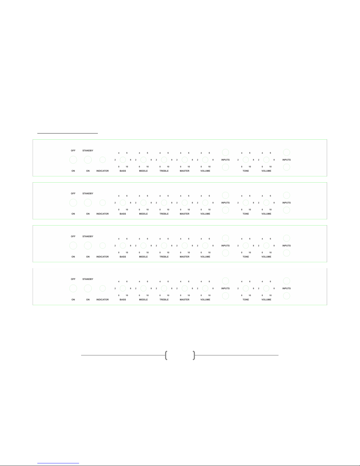
STANDBY applies high voltage to the vacuum tube anodes (and screen grids) during use of the amp.To ensure long tube life,
first power the unit on with the STANDBY toggle switch in UP position for approximately 30 seconds. You can then switch to
DOWN (“ON”) to use the amp. With the toggle switch in the UP position, the amp is in STANDBY mode. In the DOWN
position, the amp is in OPERATE mode
INDICATOR will illuminate when the amp is powered by turning the front panel POWER toggle switch to the ON position. If
INDICATOR does not turn on, check your power cable connections, and then the fuse on the rear of the unit.
BASS adjusts low frequencies
MIDRANGE adjusts the mid frequency response
TREBLE adjusts the high frequency response
VOLUME sets the overall gain and distortion level of the TMB channel of the amp.
MASTER VOLUME sets the overall volume level of the TMB channel of the amp.
INPUT ¼” jack for instrument cables. Plug your guitar in here for the TMB Channel. The UPPER input is higher gain, whereas
the LOWER input is lower gain.
TONE adjusts the frequency balance for the NORMAL channel. At counter-clockwise settings, the tone has more bottom end
and less treble. At clockwise settings, the tone has less bottom end and more treble.
VOLUME sets the overall volume and gain of the NORMAL channel of the amp.
INPUT I and II are ¼” jacks for instrument cables. Plug your guitar in here for the NORMAL Channel. The UPPER input is
higher gain, whereas the LOWER input is lower gain.

!
!
6
4) REAR PANEL CONTROLS
From left to right:
1) NEGATIVE FEEDBACK 2-way toggle switch
2) OUTPUT IMPEDANCE ¼” speaker jacks (x3)
3) POWER 2-way toggle switch
4) MAINS FUSE
5) MAINS IEC cable inlet
NEGATIVE FEEDBACKtoggle switch adds or defeats negative feedback in the power amplifier. UP engages negative
feedback, which will tighten the response of the amp and decrease breakup and harmonic content. DOWN defeats the
negative feedback, which eases the transition to breakup, and increases the bandwidth of the power section.
OUTPUT IMPEDANCE ¼” speaker cable jacks. Use a ¼” speaker cable to connect your speaker cabinet to the amplifier using
these jacks. If you use one speaker cabinet, either jack is acceptable. Plug your cabinet into the jack that matches the total
impedance of your cab to the number above the jack (16, 8, or 4 Ohms)
NOTE – never turn your amplifier to OPERATE mode (“ON” / DOWN position on STANDBY) without connecting the amplifier to
a speaker cabinet or suitable dummy load! Failing to do so may damage your amplifier!
POWER switches the power output of the power amp. For the 36W, half mode is approximately 18W. LO mode configures the
power tubes to run in triode operation, and this negates any need to reconfigure the OUTPUT IMPEDANCE.

!
!
7
MAINS FUSE slow-blow fuse – used to protect your amplifier from voltage spikes or excessive current draw. Replace only
when necessary with 2A Slo-Blo
MAINS IEC cable inlet – plug a suitable IEC power cable into this inlet to power your amplifier

!
!
8
5) TUBE COMPLIMENT AND BIAS ADJUSTMENT
!
From left to right:
V1 – 12AX7/ECC83 (Input stage Normal and TMB channel)
V2 – 12AX7/ECC83 (phase inverter)
V3 – 12AX7/ECC83 (TMB Stage 2 and cathode follower)
V4-7 – EL84
V8 – GZ34/5AR4
Amplifier is cathode-biased and requires NO BIAS ADJUSTMENT when installing new power tubes!

!
!
9
6) FREQUENTLY ASKED QUESTIONS
How do I hook up this thing?
-See Section 2, beginning on page 3.
Can I substitute different tube types?
-Although you can try 12AT7s, 12AU7s, 5751s without any harm, the design is optimized for 12AX7s, and are
therefore the only recommended tube in the preamp positions. You must use EL84s and a GZ34
Do I need to use a matched and balanced phase inverter?
-It is not necessary. Feel free to experiment with different tubes (of the same type) in your amp, though!
I’ve read that the components used in this type of amplifier are really important. What is inside my amplifier?
-We use a combination of parts custom-made for us to our specifications (power transformer, output
transformer, choke, high-temperature / low-ESR electrolytic capacitors) and those used in our British series
(1/2W carbon composition resistors, 1W carbon film resistors, TAD Mustard capacitors, high-voltage silver
mica capacitors, Belton tube sockets, and Alpha potentiometers, Cliff jacks). Finally, we occasionally use
NOS components from our vast surplus parts collection in locations they work well and complement the
voicing or enhance the performance of the amplifier.

!
!
10
7) SETTINGS TEMPLATES

!
!
11
Table of contents
Other Ceriatone Amplifier manuals

Ceriatone
Ceriatone Chupacabra HRP Series User manual

Ceriatone
Ceriatone Dizzy 30 User manual

Ceriatone
Ceriatone JTM50 User manual

Ceriatone
Ceriatone Bluesbreaker JTM45 User manual

Ceriatone
Ceriatone 2550 User manual

Ceriatone
Ceriatone AFD 35 User manual

Ceriatone
Ceriatone AH Deluxe 50 User manual

Ceriatone
Ceriatone Ceriatone User manual
Popular Amplifier manuals by other brands

Cambridge Audio
Cambridge Audio 851E user manual

Creek Audio
Creek Audio Destiny 2 operating instructions

Boulder
Boulder 1012 DAC Preamplifier owner's manual

Behringer
Behringer Ultrabass BX600 Technical specifications

STUDER REVOX
STUDER REVOX A720 operating instructions

ESX
ESX QUANTUM QXFA6.2C installation instructions