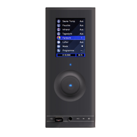
ELEKTRODESIGN Digireg evo.018 User manual

de.elektrodesign.cz
CONTROL MODULE
Digireg®evo.018
user manual
User manual
Elektrodesign Digireg®evo.018
version 2022 EN 1.0
Digireg®evo.018 switchboard Digireg®evo.018 IP65 switchboard Company of Soler & Palau Ventilation Group

2Control Module
Digireg®evo.018
elektrodesign@elektrodesign.cz |de.elektrodesign.cz
Contents
General .................................................................................................................................... 3
Introductory information to Digireg®controller..................................................................... 4
Principles of heat recovery ventilation.................................................................................. 4
Selection of HVAC unit type according to function............................................................. 5
Heat recovery unit + circulation (heating) ............................................................................. 5
Supply air unit, supply and exhaust air unit.......................................................................... 5
Selected HW and SW parameters - explanation of function and use ............................... 6
Ground collector................................................................................................................... 6
Preheating + cooling............................................................................................................. 6
Heating + bypass + mixing damper...................................................................................... 7
Circulation + boost + RH + summer/winter mode switching................................................ 8
Anti-freeze protection for water coil ..................................................................................... 9
Anti-freeze protection for heat exchanger ............................................................................ 9
Bivalent heating for heat pump............................................................................................. 9
Connection and operation of heat pump / or condensing unit........................................... 10
Heat pump defrost mode.................................................................................................... 10
Dynamic temperature control ............................................................................................. 11
Equal-pressure ventilation .................................................................................................. 11
„Fire alarm“ input response ................................................................................................ 11
HW blocking input response............................................................................................... 11
Fan control in automatic mode........................................................................................... 11
Response to changes in temperature and fan speed settings during pre-set schedule.... 12
Programmable time schedules........................................................................................... 12
Cool down period for electric and gas heating................................................................... 12
Control of air dampers........................................................................................................ 12
Important notes on assembly and installation .................................................................. 13
Interconnecting Digireg®CP TFT controller with another regulator.................................... 13
Connection of the communication cable to the terminal block....................................... 14
Description of operations and display of values on Digireg®CP TFT control module .. 15
Setting time schedules ....................................................................................................... 16
Current day and time setting .............................................................................................. 17
Alarms, reporting errors and alarm history ......................................................................... 17
Adjusting the position of mixing damper and bivalence..................................................... 18
Access to service settings.................................................................................................. 18
Types of basic system icons displayed on remote control module.................................... 19
Description of icons displayed on control module + operating modes .......................... 21
Unit operation and alarm icons........................................................................................... 21
Icons used as bottoms to adjust unit function ................................................................... 22
Additional control module adjustments and functions ....................................................... 23
Technical support................................................................................................................. 24
Unit decommissioning ......................................................................................................... 24
Disposal and recycling......................................................................................................... 24
Technical list and registration sheet................................................................................... 25
Warranty claim form............................................................................................................. 26

3
Control Module
Digireg®evo.018
user manual Elektrodesign Digireg®evo.018 |version 2022 EN 1.0
General
INTRODUCTION
This manual refers to Digireg® evo.018 con-
trol module. The intention of this manual is
to provide information in regards to Digireg
installation, commissioning and use. Due
to the fact that our products are constantly
evolving, we reserve the right to change this
manual without any prior notice.
WARRANTY
We do not guarantee compatibility of this
device with any other special usage there-
fore, the determination of compatibility falls
upon full competence of customers and
project engineers. The warranty for this mo-
dule goes in accordance with the valid legal
regulations. The warranty is considered valid
if all installation and maintenance instruc-
tions were fully followed. Digireg warranty
covers manufacturing defects, material
defects or malfunctions of the device.
The warranty does not cover defects
caused by:
– improper use and design
– improper handling (does not apply to
mechanical damage)
– transport (compensation for damage-
caused during transport must be claimed
from the carrier)
– incorrect installation, incorrect electrical-
connection or inadequate protection
– incorrect operation
– unauthorized device tampering
– disassembling of the device
– use in unfit conditions or in an unsuitable
manner
– normal wear and tear
– third party intervention
– due to a natural disaster
With warranty claim, it is necessary to
submit a report containing:
– information regarding the person or
– company generating the claim
– date or purchase and invoice number
– description of the defect
– wire connection diagram
– measured values during the startup
• voltage
• current
• air temperature
ELEKTRODESIGN ventilátory s.r.o. reserves
the right to decide whether warranty repair
work will be done on site or at the company
service center. The method of correcting the
defect is solely at the discretion of the servi-
ce company ELEKTRODESIGN ventilátory
spol. s r.o. The complaining party will receive
a written statement stating the result of the
complaint. In any event of an unjustified
complaint, the complaining party pays all
costs associated with repairs.
Warranty conditions
Digireg must be installed by qualified per-
sonnel or by a professional HVAC company.
The electrical connection must be made by
qualified electrical company. Installation and
location of equipment must be performed
in accordance with ČSN 33 2000- 4-42 (IEC
364-4-42). The device must be subjected to
initial electrical inspection according to ČSN
33 1500. The device must be set to meet
the project specifications. During the first
startup, it is necessary to measure all speci-
fied values and record those measurements.
Those will be confirmed by a company
providing the unit commissioning. In the
case of any future warranty claim it will be
necessary to submit a full record of the
above-mentioned parameters together with
the complaint, including the initial revision,
generated during the initial startup.
During normal operation, it is necessary
to perform regular inspections of electrical
equipment according to ČSN 33 1500 and
to perform inspections and maintenance on
the unit.
After receiving and unpacking the module
from transport packaging, the customer is
obliged to perform following inspections. It
is necessary to check for any damages as
well as whether the device delivered reflects
the device ordered. It is necessary to check
whether the shipping label and identification
data on shipping packaging, equipment
label or motor model number correspond
to project specifics and that it meets what
was ordered. Due to the constant technical
improvements of the equipment and chan-
ges in technical parameters, and due to a
certain time lag between ordering and order
processing, the manufacturer reserves the
right to implement changes to equipment
without notifying the customer.
The customer is responsible for inquiring
about any equipment changes before ma-
king the final order. Subsequent complaints
cannot be taken into account.
CIVIL LIABILITY
The Digireg®evo.018 control unit is de-
signed primarily for control of air handling
units. Neither the manufacturer nor the seller
is liable for defects caused by:
– inappropriate use
– normal wear and tear of components
– failure to observe the instructions for
safety, use and commissioning specified
in this manual
– not using the manufacturer‘s original
components
SAFETY REGULATIONS
Adherence to these instructions should not
pose any safety, health or environmental
risks in accordance with EC directives (CE
marked). The same applies to other pro-
ducts used in the device or during installati-
on. Consider the following warnings:
– Follow the safety instructions to prevent
damage to the device or personal injury.
– The technical information in this manual
must not be changed.
– It is forbidden to interfere with the motor
of the device.
– The motors of the device must be conne-
cted to a single-phase 230 V / 50 Hz AC
mains supply.
– In order for the device to comply with EC
directives, the device must be connec-
ted to the mains in accordance with the
applicable regulations.
– The equipment must be installed in such
a way that, under normal operating con-
ditions, it cannot come into contact with
any moving and/or live part.
– The device complies with the applicable
regulations for the operation of electrical
equipment.
– Always disconnect the device from
thepower supply before carrying out any
work on it.
– Appropriate tools must be used when-
handling or maintaining the device.
– The device must only be used for the
purposes for which it is intended.
– This appliance is not intended for use by
children under the age of 8 and persons
with reduced physical, sensory or mental
capabilities, or lack of experience and
knowledge, unless they are under the
supervision of a responsible person or
they have been sufficiently instructed in
the safe use of the equipment, and for
whom the risks associated with it cannot
be understood. The user must ensure
that children do not play with the device.
Cleaning and maintenance of the appli-
ance must not be carried out by children
without supervision.

4
elektrodesign@elektrodesign.cz |de.elektrodesign.cz
Digireg®evo.018
Introduction
Introduction of the Digireg®evo.018 controller
Digireg®evo.018 control module was de-
signed to control air handling units manu-
factured by ELEKTRODESIGN Ventilator
s.r.o. and the Soler & Palau Ventilation
Group. Each Digireg module can control one
piece of air handling equipment (unit) fitted
with heat recovery module and some type
of heater and cooler. Source of heating can
come in form of electric heat strip, hot water
coil, gas fired unit or heat pump. Cooling
can be provided by chill water coil, DX coil
or heat pump. Under a certain technical
condition, Digireg® can be used to control
forced air heating. In such a case, Digireg
controls two units. Indoor unit - circulating
air with either heating or cooling provisions
and additional heat recovery unit – providing
ventilation with its own control.
The basic function of Digireg control module
allows for the controller to be installed with
a majority of air handling units coming from
different manufacturers. The only limiting fac-
tor for Digireg use is the need to use TGCU
(TGCK) type of temperature sensors. Other
inputs and outputs use unified signal values
and common components which are typical
of any hybrid HVAC control product range.
The controller can be also used on devices
with significantly higher output of heating
and higher fan output than is permitted by
preinstalled protection elements; such an
installation will be conditioned by external
main switch design, power breaker and
safety contactor.
Digireg®evo.018 controller is a micropro-
cessor controlled, single-purpose system
which functions and uses are defined in the
product catalogue sheet. The catalog sheet
can be found at ELEKTRODESIGN ventilá-
tory s.r.o. website or in ELEKTRODESIGN
catalog. The wiring configuration and device
settings shall be performed by authorized
technician and with considerations to custo-
mer‘s request however, only in compliance
to the range of functions and values listed in
the catalogue sheet and installation manual.
Setting of parameters is done by special
configuration software.
When required for any other application, or
function or combination of device functions
that are not listed in the catalogue sheet or
in the manual, it will not be possible to use
this type of controller. In such cases, another
brand of programmable control device must
be used.
This operation manual is designed for
basic user operation procedures and for
installation of air handling equipment. During
unit commissioning, and when the unit is
equipped with Digireg®evo.018 controller
and the Digireg®CP TFT controller, commi-
ssioning technician must provide the owner/
operator with all information regarding to the
safe operation of the equipment and must
demonstrate all unit functions in regards to
the equipment.
The controller commissioning and thus
commissioning of the entire air handling unit
must be performed by a qualified company
in close cooperation with authorized service
technician who is familiar with the controller.
Depending on the equipment accessories,
cooperation of several trades (electrical
engineering, refrigeration tech, HVAC tech)
during unit commissioning might be nece-
ssary.
Any service technician working with the
controller must possess a registered certi-
ficate of competence. The commissioning
technician must then provide his registra-
tion certificate number and write it in the
Technical and Registration Sheet which
is included with each unit. In the event of
non-completion of the said protocol and mi-
ssing certificate number, the equipment shall
be treated as non-commissioned and will
not become a subject to the warranty claim
conditions. Detailed list of all equipment
requiring authorized start-up procedure is
listed on the website. Also listed is a link to
ELEKTRODESIGN’s service center.
The principle of heat recovery system
The main function of any heat recovery unit
is to preheat (or pre-cool) incoming outside
air by carrying air through a heat recovery
module. This process of heat recovery varies
based on outside air temperature and unit
configuration. The heat recovery module is
used for economical preheating or pre-coo-
ling of outside air and only after the initial
outside air preconditioning, electric or water
heating/ cooling is applied to meet the actu-
al temperature that is desired. This process
of heat recovery saves a large amount of
energy while still ensuring excellent indoor
air quality. AHU’s control system evaluates
the heat recovery option by collecting data
coming every minute from temperatures
sensors and also by considering AHU
settings.
Demand for heating and cooling is proce-
ssed by Digireg control system and it is
distributed between heat recovery module
and additional added source of heating or
cooling. The amount of heat recovery usage
is regulated by air by-pass. The higher
usage of by-pass equals to smaller usage of
a heat recovery module.
Heating
Electric heat strip, hot water, gas fired
burner or heat pump:
0–25%
of efficiency is transferred to heat recovery
module and recuperator
25–100%
of efficiency is converted to heating
0–100%
Cooling adjustable
cold water or heat pump
0–25%
of power is transferred to the use of
a recuperator
25–100%
of power is converted to cooling 0–100%
Cooling on/off
compressor or heat pump on/off
0–50%
of power is transferred to the use of
a recuperator
50–100%
of power is converted to cooling 0–100%

5
user manual Elektrodesign Digireg®evo.018 |version 2022 EN 1.0
Digireg®evo.018
Selection of the type of HVAC unit
Heat recovery unit
Air handling device coupled with heat reco-
very module and fans which provides remo-
val of stale air (exhaled air, containing faulty
odors from kitchen, toilet etc.) to outside
the building and its replacement with fresh,
heated (cooled in summer) air. Provides
controlled ventilation with heat recovery thus
ensures optimal use of already produced
(and already paid for) heat with high effici-
ency (in the case of using EDV units up to
97 %). In summer, on the other hand, this
ventilation can be used to cool the living
space. The heat recovery module could be
built either as fixed plates, or counterflow,
rotating wheel type or a liquid type.
Each unit comes fitted with supply and
exhaust fan, supply air and return air filter
and with a heat recovery module. Optional
humidity and CO2or VOC sensors provide
for „intelligent“ ventilation control (ventilation
based on current air quality inside venti-
lated space). The unit includes air bypass
which navigates air around the recupera-
tor in the warm season in order to reduce
fan resistance, therefore providing energy
savings. Different types of supplemental
heating and cooling provisions comes as an
option (electric heating, gas fired heating,
heat pump, ground collector, water heating/
cooling with mixing node).
Heat recovery + circulation (heating), hot air heating unit
Heat recovery unit interconnected with ano-
ther, circulation only unit which is dedicated
for air circulation and heating/cooling in
designated areas. Control of the circulation
(heating) unit and the heat recovery unit is
realized by one controller. All features and
options of heating unit remain standard,
as well as the possibility of adding different
types of heating and cooling provisions, or
their combinations. Only heat recovery unit’s
fan output and time mode are being cont-
rolled. Designed primarily for compact heat
recovery units with internal control, suited
for family houses and apartments, controlled
by a cable.
Supply air unit
Used for delivering fresh outdoor air to
designated areas. Each unit is fitted with
one supply fan, replaceable filter, necessary
temperature and humidity sensors as well
as CO2/VOC/SQA sensor. Different types of
supplemental heating and cooling provisions
come as an option.
Supply air and exhaust air unit
Designed for supplying fresh air and exhaus-
ting stale air without the use of heat recove-
ry option. Supply air unit is interconnected
with exhaust air unit while both units are
controlled by controller mounted on
the supply air unit. All product features
designated for supply air units remain stan-
dard, as will all the options for adding diffe-
rent types of heating and cooling provisions.

6
elektrodesign@elektrodesign.cz |de.elektrodesign.cz
Digireg®evo.018
Selected HW and SW parameters
Freecooling
Only used in Summer as to provide for
economic means of cooling under a certain
and defined, operating conditions. If the
outdoor temperature is lower than the indoor
temperature, the incoming outdoor air can be
cooled by bypassing heat recovery module in
order to cool the indoor space without use of
mechanical cooling. If the conditions are not
met, Free cooling is switched off.
Conditions:
The unit switched to summer mode.
External temperature sensor must be
connected.
Temperature required must be at least
1°C lower than the actual temperature -
weather is regulated to room temperature
(reading the room sensor / sensor located
inside the controller), or to return air tem-
perature).
The external temperature must at least
1 °C lower than the real temperature for it
to make sense to supply outside air.
Cannot be used when set to supply air
temperature control.
If the conditions are not met, the unit is
switched off.
Explanation of function and use
Availability and access to each function
listed below depends on the initial control
system settings. Initial function configuration
should be given by project documentation,
by actual design of the air conditioning
equipment and by all required functions.
These requirements must correspond with
catalogue list for the controller. The descrip-
tion should be given in the project docu-
mentation - technical report. The operation
of the device is determined by the „Local
Operating Rules“.
Ground collector
Used during summer period for cooling
and during winter period for preheating for
ventilation/recuperation. The settings must
be adapted to the yield of the collector.
Conditions:
It must be enabled in HW parameters.
External temperature sensor must be
installed.
Preheating
It is used in winter to protect the recuperator
from freezing by starting an electric, water
or other pre-heater at suction of the unit.
Preheating is triggered by a potential-free
contact depending on setting of the exhaust
air temperature limit - operation only when
preheating is required. Depending on the
version, the pre-heater must be equipped
with the prescribed security/protection
system.
Conditions:
It must be enabled in the HW parameters.
Exhaust air temperature must be lower
than the set value for unlocking the
function and return air temperature must
be lower than the operating temperature
for preheating.
The switching hysteresis is fixed at 2 °C
and the switching repetition period is at
least 2 minutes.
Cooling
Each unit can be equipped with several
types of cooling provisions:
Compressor / compressor with inverter
Chilled water coil
Heat pump with reversible evaporator coil

7
user manual Elektrodesign Digireg®evo.018 |version 2022 EN 1.0
Digireg®evo.018
Selected HW and SW parameters
Heating
The unit can be equipped with several
types of heating options:
Electric heat strip single-stage, two-stage
Hot-water coil
Heat pump with reversible evaporator coil
Combined electric heating and hot water
heating
Gas fired heater
Bypass and rotating wheel heat recovery
Heat recovery bypass allows air to go around
the recuperator. Bypass can be mounted
on both, supply air side and return air side.
With rotating wheel all streams of air will pass
through the wheel. Heat recovery is done by
moving air through rotating heat recovery
wheel. When set as a rotary recuperator with
analog control, the digital bypass output can
be used as a command to close the FM or
RRT speed controller. It switches at 5 % ana-
log signal for RRT.
Mixing air damper
Designed to mix return air with incoming fre-
sh air. Helps with energy savings when some
of the heated air being exhausted from the
interior is returning directly to incoming fresh
air by means of supply air. Can also be used
to reduce indoor humidity by increasing
fresh air supply or by reducing the amount
of air being recirculated.

8
elektrodesign@elektrodesign.cz |de.elektrodesign.cz
Digireg®evo.018
Selected HW and SW parameters
Circulation
Certain types of heat recovery units can be
switched to indoor air circulation only mode
by means of adjusting internal dampers.
With this application the circulating air can
be re-heated or cooled down without going
through heat loss that would accumulate
through mixing air together with outdoor air.
This mode can be used for quick heating
or cooling of interior space, but only when
people are absented.
The circulation mode feature sends ana-
logue output to mixing damper, modula-
ting damper opening. When circulation
mode is being used it is necessary to put
in consideration unit’s initial configurati-
on and we must also follow any hygiene
requirements for the building.
Boost
BOOST mode is used to change air flow
volume while increasing the temperature of
unit’s preset value. BOOST mode is activa-
ted by an external switch contact. BOOST
mode will stay active until the required time
setting is reached, after contact is opened.
Boost mode cannot be used at the same
time with pool ventilation settings, when
unit operation in controlled according to
water temperature in the pool.
Summer/winter mode
Summer or winter mode can be set manu-
ally via service access or, when an external
temperature sensor is installed, the unit will
select between summer and winter mode
automatically.
The current mode is indicated by either sun
icon or snowflake icon displayed on touch
screen of the controller. Actual outdoor
temperature will also be displayed.
The outdoor temperature sensor must be
installed in order for added heating and
cooling provisions to work properly.
The service technician can set the tempe-
rature shift for automatic selection of the
Summer/Winter mode by ±5 °C.
RH
Relative Humidity mode is used to increase
air flow to a preset value. It becomes active
after closing either a humidity sensor con-
tacts or another switching contact which fe-
atures adjustable run-down time period after
contact opens. The Boost and RH modes
take precedence over other modes except
unit’s OFF mode and FIRE mode.
When AHU is turned off manually, or remo-
tely via contact, or remotely via ModBus,
or from active time programs then Boost
and RH modes do not work and the unit
operation is prohibited. RH function cannot
be used at the same time as the HW lock
function.

9
user manual Elektrodesign Digireg®evo.018 |version 2022 EN 1.0
Digireg®evo.018
Selected HW and SW parameters
Heat exchanger freeze protection
Based on air pressure differential noted
across exhaust side of heat exchanger or on
temperature of exhausted air. This function
can be set using the unit configuration
software.
Unit’s freeze protection response is
configured based on heat recovery unit’s
design and also on required function of the
unit. Anti-freeze protection options can be
activated by switching unit to OFF position,
by opening bypass (on the supply side) or
by restricting the operation of inlet fan, or
by combination of opening the bypass and
switching off the unit.
Bivalent heating for heat pump
When heat pump’s output is not sufficient
to maintain selected air temperature the
unit’s controller will switch to bivalent heat.
Nevertheless, the bivalent heating will not be
activated until meeting the time delay setup
for insufficient heat pump output. This time
delay constant is set to three hours and its
intention is to eliminate rapid transitions be-
tween heat requirement during defrost cycle
and transition of the heating function to
bivalence only. After releasing supplemental
heating, the concurrence of heat sources
is regulated so that the controller reduces
demand for additional source.
Outputs used for bivalent heating:
When heat pump is being used together
with another bivalent heat source:
Electric bi-valence
1. Degree of bi-valence
Output to SSR I + JTR1
2. Degree of bi-valence
Output to SSR II + JTR2
Water bi-valence
1. Degree of bi-valence
Analogue output 0–10VJTR1
2. Degree of bi-valence
Analogue output 0–10VJTR2
Coms with the same antifreeze protec-
tion as it is provided with water heat
exchanger. First response is to attempt to
warm up water and if water temperature
continues to drop, the device is switched
off completely.
Hot water coil freeze protection
Freeze protection control is based on two
adjustable stages of temperature limits
coming from a temperature sensor which is
mounted on hot water return line. Correct
temperature sensor placement close to the
unit and good insulation around the sensor
is essential to proper function of the freeze
protection control.
The first stage temperature limit opens
mixing valve while bringing hot water to
heater exchanger.
The second stage limit opens mixing
valve providing hot water to heat exchan-
ger while unit’s fan motors and air intake
dampers are shot close at the same time.
For better reliability of freeze protection, or
when higher level of safety is required, it is
possible to connect NC switch of capillary
frost protection that will be installed in
series with the sensor.
Any freeze protection system is functio-
nal only when hot water is continuously
supplied to the unit and the power supply
is switched on. If these conditions are not
met, the protection cannot be functional
and will not prevent damage to the heat
exchanger.
ESU mixing valve must be installed as
close as possible to heat exchanger.
Maximum acceptable total pipe length
with regard to the functionality of the
system is up to 5 meters.
The optimal temperature control is
achieved when mixing valve is installed
directly at the water heater inlet and
when proper hydraulic balancing and
uninterrupted supply of heating water to
the mixing valve is provided.

10
elektrodesign@elektrodesign.cz |de.elektrodesign.cz
Digireg®evo.018
Notes on connection and operation
Notes on heat pump or condensing unit operation
Heat pump must be compatible for opera-
tion when coupled with air handling units.
This means that heat pump must have its
own temperature controller reacting on
evaporating temperature and have the
ability of controlling temperature in both
heating and cooling mode. Air temperature
after evaporator, while the heat pump is
running, must be in the range of +15 to
+40 °C. It is not possible to use devi-
ces regulating the evaporating pressure
(temperature) to low or negative values
(less than +10 °C) or use devices which
cannot be switched off with on/off signal.
Another condition is to control the defrost
by non-reversible cycle. If bivalent heating
is installed, the evaporator temperature
sensor must be installed on evaporator
outlet side, before any bivalent heater.
Digireg®comes with only one set of com-
pressor control allowing activation of one
condensing unit. For this reason, multiple
condensing unit cannot be controlled
separately. If a multi-circuit evaporator
control is required, it is necessary to use
either a multi-circuit compressor unit (with
one control regulator) or an AHU box for
controlling several units. Also, it is not po-
ssible to use a condensing unit dedicated
for split systems controlled by combined
analogue input for regulating and input for
cooling/heating switching.
Digireg’s control board heat pump outputs
correspond to industry unified set of signals:
– Signal for switching compressor ON/OFF/
or activating water cooling
– Signal for switching heat pump’s opera-
ting mode between heating and cooling/
also output for ESU mixing valve
– 0–10V signal for 0–100 % compressor
power output
0V minimum power
for cooling and heating mode
10V maximum power
for cooling and heating mode
Digireg®does not contain any autono-
mous controller that would be dedica-
ted for a heat pump function. Supplied
condensing unit must come equipped
with appropriate control module such as
AHU box.

11
user manual Elektrodesign Digireg®evo.018 |version 2022 EN 1.0
Cascade temperature control (terminals 53/54)
Mainly used for swimming pool ventilation.
After switching on Boost mode, supply
or exhaust air temperatures are regulated
according to pool water temperature, by
stepping one level above. Temperature
sensor located inside remote control module
is used in replacement of water temperature
sensor.
It cannot be used for room temperature
control based on temperature sensor
located inside remote control module.
Cannot be used together with the BOOST
function.
Equal-pressure ventilation
Stands for providing equal amount of air
coming in through the supply side and which
equals to amount of air leaving through the
exhaust side.
If AHU’s pressure sensor detects higher
than normal pressure difference across
heat exchanger (indicating risk of frozen
heat exchanger) it will automatically limit
power coming to supply fan. This func-
tion must be pre-programmed in Digireg.
Authorized service technician can preset
AHU performance for permanent positive
or negative pressure. This is done by
adjusting the power output coming to
exhaust fan by ±50% depending on the
project requirement and according to any
pressure losses accumulated in ductwork
distribution systems.
Warning: when operating HVAC units
in rooms equipped with a chimney ven-
tilated heater, and without a separate
combustion air intake, there is a risk
of reversing the flow of combustion air
leading to CO poisoning.
„Fire Alarm“ input response (terminals 69/70)
When Fire Alarm input is disconnected, the
output power of fan motors during normal
operation is set to 0-100 %. If Fire Alarm
input is not being used, it must be interco-
nnected with a jumper wire.
In order to unlock the device that was
switched to state “Fire Alarm” it is necessary
to eliminate the cause of this fault. This can
be done by means of resetting the unit by
switching the main power to OFF and ON
position.
Under no circumstances shall be the AHU
used for fire or fire safety ventilation.
When the fire alarm contact becomes
open the AHU will switch to OFF position
in order to prevent any smoke recircula-
tion.
Digireg®evo.018
Selected HW and SW parameters
HW blocking input response (terminals 67/68)
When HW input becomes opened, and after
AHU runs through standard cooling down
period, the AHU goes into the blocking sta-
te. All unit’s outputs are switched to off po-
sition and the unit cannot be switched to on
position by control module or by accessing
service SW. Anti-freeze protection for heat
exchanger and fire alarm mode remain avai-
lable and active. When HW blocking input
closes once again the unit switches back
to normal operating state, corresponding to
the last unit operating mode programmed in
control module or based on the last progra-
mmable time schedule.
HW blocking input cannot be used toge-
ther with RH mode reading info from a
humidistat.

12
elektrodesign@elektrodesign.cz |de.elektrodesign.cz
Digireg®evo.018
Selected HW and SW parameters
Response to temperature and fan speed settings while running time programs
When controlling AHU with pre-programmed
time period any manual program changes
activated by a user will be valid only up to
next preprogrammed time period.
In order to run manually adjusted program
continuously it is necessary to switch
preprogrammed time setting to off position.
This can be done by deactivating a time
program icon which is located on remote
display control module
Time programs
Seven days programable setting is available.
Time programs provide option to program up
to eight time periods daily for every day of
a week separately. Each time period can be
assigned with requested temperature setting
and fan power performance. The shortest
time interval can be programmed to period
of 5 minutes. The time periods must be set in
ascending order, the time period sequence is
automatically cross-checked and any alloca-
ted time slot overlap cannot be set.
It is possible to copy and paste program-
med daily time periods.
Rundown, cooling time period for electric and gas heating
The rundown time period is fixed at:
Wire heater - 2 minutes.
Electric strip heater - 4 minutes.
Gas fired heater - 3 minutes.
Control of air dampers
Digireg®controller provides separate output
terminals to control supply air damper and re-
turn air damper. Start sequence to modulate
dampers to open or close position is delayed
by adjustable interval of 30 to 240 seconds.
Both dampers must have common source
of power supply, combination of 24 VAC and
230 VAC is not possible.

13
user manual Elektrodesign Digireg®evo.018 |version 2022 EN 1.0
Digireg®evo.018
Important notes on assembly and installation
Cable connection
Digireg®CP TFT control module must be
connected with Digireg®control board
with a SYKFY or UTP 2x2x0.5 type of data
cable. When only a short cable is needed
2x2x0.25 or an equivalent type of twisted
pair cable is acceptable. When a thicker
type of wire is used, protentional damage
to control board connectors becomes
likely. Improper wire connection could lead
to faulty display on control module or faulty
signal transmission.
Main disconnect enclosure with control
board, including all wire cabling, must be
properly secured to AHU or to building
structure. In a case where connecting
cable distribution runs inside pre-installed
cable supporting structure, the wiring must
be made with stranded conductors and
secured tightly against being pulled out of
the control module or the control board, in
accordance with ČSN-EN.
The authorized service technician will
not commission AHU unless the cable
harness running between control module
and control board is properly fastened.
Outdoor rated electrical enclosure, when
installed outdoors, must be installed away
from direct sun exposure and must be
shielded from rain and snow (installed
under a roof with a sufficient overlap). Fai-
lure to observe these basic principles will
cause a significant reduction to life of all
electric parts located inside the enclosure
and possible permanent damage. Out-
door type enclosures with increased IP65
protection are only produced up to the
maximum size listed as M3-Vx, M1-E8-2
or M3-E15. Where outdoor installation is
required SSR relays will be mounted inside
the AHU, on the return air side of the unit.
The outdoor enclosure must be installed
in a freely ventilated place. When electric
heating is part of the installation, asso-
ciated heat sink is mounted on the right
side of the enclosure and it requires good
circulation of cooled air. When installed
inside of another enclosure or unventilated
space, it is necessary to ensure sufficient
air ventilation.
Manostats (differential pressure sensors)
which are located inside each AHU must
be adjusted according to the AHU’s actual
performance and considering installed
HVAC ductwork and accessories. Manostat
adjustment involves manostats dedicated
for filter clogging, manostats confirming
fan operation and manostats sensing
freezing up of heat recovery module. Initial
manostat setting based on project values
comes preset from the manufacturer
Smoke detectors must not be connected
to power supply that is dedicated for Digi-
reg®control board. The initial unit start-up
process switches from on and off causing
the smoke detectors to signal Fire alarm.
It is necessary to provide a separate and
protected power supply dedicated to smo-
ke detector which will be located before
the main Digireg power switch.
Analogue sensors with uninsulated output
voltage must not be powered from Digireg®
switchboard transformer. Separate power
supplies must be used, optimally for each
sensor separately or sensors with direct
230 VAC supply.
Connection of Digireg®CP TFT control module
Digireg®CP TFT touch screen control mo-
dule may only be used with Digireg®evo.018
control board. It is not compatible with
Digireg®CP monochrome controller or with
Digireg®HW1 regulator.
The control module is intended for place-
ment in areas intended for people occu-
pation. The control module protection
corresponds to the IP20 classification.
When installed in exteriors, bathroom areas,
swimming pool areas, industrial kitchens it
is necessary to provide additional control
module protection.
The control module must be connected to
its control board with a SYKFY 2x2x0.5 or
equivalent (UTP) data cable.
During the first installation, it is necessary
activate CR 2032 battery which stores set
time, date and programmed parameters -
the installed battery has an insulating strip
and it must be removed by carefully pulling
it out. The battery life expectancy during
normal usage is up to 10 years.

14
elektrodesign@elektrodesign.cz |de.elektrodesign.cz
Digireg®evo.018
Assembly and installation notes
Description of data terminals connection:
1) White green – RS485 / signal B —> Digireg®terminal 60
2) Green – RS485 / signal A —> Digireg®terminal 59
3) White orange – power supply / GND —> Digireg®terminal 58
4) Orange – power supply / +12VDC —> Digireg®terminal 57
The controller base must be installed on a
level surface (optimally installation box 68 to
the plaster-board) using suitable fastening
screws. The heads must not protrude above
the level of the base.
After the wires of the communication conne-
ctor have been fitted correctly (Fig. 1), the
connector can be inserted and the contro-
ller itself can be fastened with the correct
screws. Mounting screws (Fig. 2) of the
controller on the base in the picture below.
Damage of the threads can lead to inco-
rrect fastening and damage to the device,
responsibility of the installer.
After mounting, the top cover frame must be
installed. It is necessary to proceed by pu-
lling it from the bottom up, on the underside
there is a hole for the internal temperature
sensor.
Fig. 1
Fig. 2
Connection of communication cable to terminal board
J1 connection terminal block is equipped
with a special connector with self-locking
contacts for connecting a fixed conductor
(wire) with diameter 0.25 to 1 mm.
Any other different diameter cable is used it
must be transitioned in by an adapter, which
can be ordered.
Figure 1 shows the position of CR 2032
backup battery. The battery life expectancy
during normal usage is up to 10 years.
Figure 1 shows J2 connector dedicated for
optional connection for an external room
temperature sensor.
Below it is a four-pin connector J1 for co-
nnecting the base to the controller.

15
user manual Elektrodesign Digireg®evo.018 |version 2022 EN 1.0
Digireg®CP TFT
Description of controller operation
Photos of graphic display are used for
clarity.
The individual screens can differ in actual
design and operation.
Display of data reading when AHUs power supply is switched on
When the main switch or main power bre-
aker is turned on, „Searching for air handling
unit“ screen appears. After communication
with AHU is secured, the basic screen is
displayed.
If the controller keeps searching for AHU,
there is a communication wire issue. The
wires may be broken or wire order may be
reversed.
Basic screen display when AHU is turned off
Basic screen display when AHU is turned on
The lower middle “Play” icon, as displayed
on attached picture, signals operation of the
unit based on preset “time program”. When
the unit is running with “time program” in
stop notion, this function is indicated by
“Pause” icon. By pressing the “Pause” icon
the unit returns back to run “time program”.
Default screen for adjusting different values
Default screen for adjusting temperature
value, fan speed value and access to misce-
llaneous items.
Setting desired temperature value
Setting desired temperature value after
clicking on the thermometer icon.

16
elektrodesign@elektrodesign.cz |de.elektrodesign.cz
Digireg®CP TFT
Description of controller operation
Access to miscellaneous items
Access to miscellaneous items, after
clicking on the miscellaneous items icon
located on previous screen. Description of
icons, from left to right and from top to
bottom:
1) Icon for access to program settings.
2) Empty space reserved for mixing contro-
ller or bivalent reheating item.
3) Icon for access to language options.
4) Icon for displaying graphical visualization
of current system operation.
5) “Arrow” icon to return to the previous
screen.
6) Actual date and time settings.
7) Icon for access to service menu (access
code is required).
8) Icon for a fault display and access to
fault history.
Setting fan speed value after clicking on the fan icon
By clicking on „arrow left“ icon, we will
return one step back to the home screen.
By clicking on icon with symbols located to
the right, we go either to temperature or fan
power settings.
AHUs set to equal-pressure ventilation have
only one fan icon available, which equals to
one fan setting. AHUs set to independent
pressure setting will have one icon for supp-
ly air pressure and one icon for exhaust.
Shown in the photo.
Setting of programs running in time intervals
By clicking on the “program settings” icon
we can create or modify unit’s operation
during different time intervals. This option
offers up to 8 programmable time sections
per day, seven days per week. Minimum run
time for each programmable section is 5
minutes, time overlap is not allowed. Inside
each time section we can set duration of
current time interval, adjust temperature
settings and adjust fan speed.
Access to each time section and adjustable
options is intuitive by clicking on the corre-
sponding symbol.
Time interval setting, green color digit dis-
play indicate that current period is OK, red
color digit indicate a time overlap. The green
color check mark saves the interval, the
red color trash symbol deletes the interval.
The “Arrow” icon pointing left will display
air temperature and fan speed adjustment
screen.
Setting for desired air temperature and fan
speed.
Graphic interpretation of current time
intervals together with air temperature se-
ttings and fan speed settings.

17
user manual Elektrodesign Digireg®evo.018 |version 2022 EN 1.0
Digireg®CP TFT
Description of controller operation
Actual day and time settings
Proper operation of RTC calendar and clock
requires activation of CR 2032 battery by
removing inserted insulation tape and by
programing current day and time.
If a battery fault is displayed on control
module the battery must be replaced.
Daily time programs can be copied to
across the weekly calendar.
Language settings
Language options available are Czech,
English, German, Spanish, Russian, Slovak
and French.
In service access menu English and Czech
language is used.
System running errors, error reporting and system fault history
Error messages will be displayed on fault
display screen by error number. When the
error is active, corresponding error number
will be framed in red. The “ribbon” symbol
located at the bottom right allows access to
the error history, up to 250 recordings.
By clicking on individual error number, we
can access the error’s history by acknowled-
ging the error.
The actual restart of AHU is performed by
switching the control module OFF and ON.
Restart is also possible by switching the
AHU main power supply OFF and ON.

18
elektrodesign@elektrodesign.cz |de.elektrodesign.cz
The bivalent heat source option may be
activated or deactivated by the Biv OFF
icon located to the right side of the display.
Actual switching on for bivalent heat
depends on preset setpoint and switching
time of the continuous heating demand.
During normal operation the main source
of heat is provided by a heat pump and an
auxiliary source of heat comes on as se-
cond. If necessary, the auxiliary source can
be set as an emergency heater by adjus-
ting temperature values for blocking heat
pump’s operation based on the outside
temperature.
Digireg®CP TFT
Description of controller operation
Adjusting settings for mixing damper and for bi-valent heat
Accessible only when programmed and
enabled during initial unit commissioning.
Mixing damper icon will be displayed in the
same location as may be displayed icon for
bivalent heat source for heat pump.
Access to service settings
Can be accessed only by entering appropri-
ate codes.
Accessing the service setting gains access
to selecting the initial screen display, bloc-
king parameters access to unauthorized
personnel etc.
Password for service access: .................
Password to lock the display: 8080
Display customization password: 1110
Icons for mixing valve or bi-valent heat on the home screen
If both functions are programmed, we can
access the second setting that is located in
a submenu after clicking on the first displa-
yed function.

19
user manual Elektrodesign Digireg®evo.018 |version 2022 EN 1.0
Digireg®CP TFT
Description of controller operation
Service settings - setting hardware parameters
Service setting - setting software parameters
Service setting - setting controller parameters
Access to the service menu is possible
after entering appropriate password by
an authorized technicians.
Examples of graphical visualizations
Supply air unit with electric heating and
mechanical cooling. Active time interval
program settings.
Supply air unit with hot water heating and
mechanical cooling. Active time interval
program settings.
Supply air and exhaust air unit coupled
with electric heating and mechanical coo-
ling. Mixing valve and active time interval
program settings.

20
elektrodesign@elektrodesign.cz |de.elektrodesign.cz
Digireg®CP TFT
Description of controller operation
Heat recovery unit with hot water heating
and mechanical cooling. Active time inter-
val program.
Supply and exhaust air units coupled with
hot water heating and mechanical cooling.
Active time interval program settings.
Heat recovery unit with electric heating
and mechanical cooling. By-pass damper
and mixing air damper with active time
program.
Table of contents
Popular Control Unit manuals by other brands

SMC Networks
SMC Networks VM400 Series Operation manual

Sierra Wireless
Sierra Wireless AirPrime HL8518 Product Technical Specification

Demex
Demex Easy GSM Firmware update instructions

oventrop
oventrop Cocon QTZ technical information

Littfinski Daten Technik
Littfinski Daten Technik RM-88-N-O-B Assembly instruction

ICP DAS USA
ICP DAS USA M-7016 quick start guide