ELEKTROMET PANNEX DUO COMBI VVB 160L User manual

ver.01/2 PANNEX DUO COMBI VVB 160L
1
HOT TAP WATER HEATERS
type WJ/W-Q
with a helical coil and
an electric heater
INSTALLATION AND USER’S MANUAL
GUARANTEE TERMS

ver.01/2 PANNEX DUO COMBI VVB 160L
2
INDEX
1. CONSTRUCTION AND USE …………….……………….……………….……………….………………3
2. INSTALLATION …………….……………….……………….……………….……………….…………….5
Connecting to the water supply and central heating systems…………….……………….…………….5
Connecting to the wiring system …………….……………….……………….……………….…………..6
Connecting to the circulation system …………….……………….……………….……………….……...6
Start-up …………….……………….……………….……………….……………….………………….…...7
3. MAINTENANCE AND USAGE …………….……………….……………….……………….…………….7
Operation of the heater connected to a boiler …………….……………….……………….…………….7
Maintenance tips …………….……………….……………….……………….……………….……………7
Magnesium anode rod replacement …………….……………….……………….……………….……….7
4. WARRANTY TERMS AND CONDITIONS…………….…………………….……………….……………8
Please read „Instructions for Use” and „ Warranty Terms and Conditions”
carefully before heater installation and start up.
Heater installation and start up should be performed in accordance with the
“Instructions for Use” by a qualified person.

ver.01/2 PANNEX DUO COMBI VVB 160L
3
1. CONSTRUCTION AND USE
WJ/W-Q type water heaters with spiral coil pipe are used for heating usable water
and its storage. They can be used in houses, small blocks of flats and other types of
buildings equipped with low-temperature water boilers and electric supply of ~400V
(in case of the heaters with the electric heater). These appliances are ready to
operate with the water supply systems with pressure of 1,0 MPa.
In both types, the heating water necessary to heat the usable water is delivered
(e.g. from the central heating boiler) to the spiral coil pipe, which has a big heating
surface and is installed inside the tank of the heater. The heating water inside the
pipe heats the surface of the coil pipe which warms the usable water stored in the
tank.
The pressure tank is made of steel sheet covered with a layer of ceramic enamel
inside, which together with the magnesium anode rod installed in the top end cap
protects the tank against corrosion and guarantees good quality of the usable water.
The anode rod functions on the basis of the difference between the electrochemical
potentials of the anode rod and the tank materials. The access to the anode rod
which requires periodical inspection and replacement is secured by a removable
insert The tank is insulated with polyurethane foam (contains no FCKW) screened
with metal jacket made from thin steel sheet covered with powder paint and upper
and lower plastic lids. The heaters should be mounted on walls or other suitable and
solid constructions in vertical position.
The heater PANNEX DUO COMBI VVB 160L is additionally equipped with the
so-called “dry” electric heater with the heating power of 3000 W supplied with the
three-phase electric current of ~400 V. In this type of heaters it is possible to
replace heating elements without the necessity of draining the tank.
Thanks to modern construction and technologies used to produce the WJ/KW
types heaters they are economical, durable and their installation, usage and
maintenance are easy and safe. They can be installed in every type of room with the
water-supply and wiring system connections, except for the places where the danger
of explosion or fire may occur or in which the temperature may fall below 0°C. Pic.
1 presents the construction and dimensions of both versions of the heater.
ver.01/2 PANNEX DUO COMBI VVB 160L
4
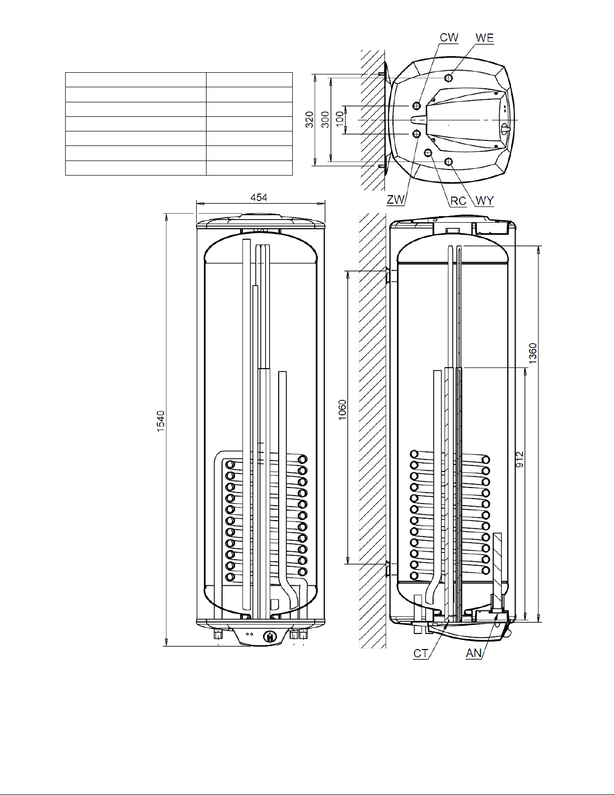
Picture 1. Construction and dimensions of PANNEX DUO COMBI VVB 160L heaters.
Table 1. Technical specification of PANNEX DUO COMBI VVB 160L heaters
WE –Heating Water Inlet
¾”
WY –Heating Water Outlet
¾”
CR –Circulation
¾”
ZW –Cold Water
¾”
CW –Hot Water
¾”
CT –Temperature sensor
ø16 mm
AN –Magnesium Anode
1¼” [30 x 270]

ver.01/2 PANNEX DUO COMBI VVB 160L
5
Type
PANNEX DUO COMBI VVB 160L
Capacity
dm³
158
Coil surface
m²
0,9
Coil capacity
dm³
4,0
Permanent usable water heating capacity
80/10/45ºC*
70/10/45ºC
60/10/45ºC
dm³/h
337
253
190
Permanent heating power
80/10/45ºC
70/10/45ºC
60/10/45ºC
kW
15,3
11,5
8,6
Demanded amount of heating water
m³/h
3
Heating water flow resistance in coil
mbar
120
Sound power level
dB
15
Water heating energy efficiency class
C
Annual electricity consumption
kWh/a
2652
Declared load profile
L
Specific energy efficiency
%
39
Tank operating parameters
Max. pressure and operationl temp.
pr=1,0 MPa tm = 80ºC
Heating agent parameters
Max. pressure and operationl temp.
pr=1,0 MPa tm = 100ºC
Heater mass w/o water
kg
77
WE –heating water supply
G out.¾”
WY –heating water return
G out.¾”
CR –circulation
G in. 1/2”
ZW –cold water
G out.¾”
CW –hot water
G out.¾”
CT –temperature sensor
ø16
80ºC, 70ºC, 60ºC – heating water temp. at coil pipe inlet
10ºC –usable cold water temp.
45ºC – usable hot water temp.
Technical specification of the electric heater installed
Nominal voltage ………………….…...400V 50Hz
Heater nominal power………………...3000 W
Water temperature control range….....20 - 75ºC
2. INSTALLATION
Taking construction of the heater into consideration, it must be mounted
vertically with the use of the mounting holders situated on the back side of the casing
(see picture 1). Before installation it is advised to make sure that the wall on which
the heater is to be mounted is solid enough and the hammer drive plugs are suitable
for the type of the wall and the mass of the heater filled with water.
Connecting to the water-supply and heating systems.
The heater is meant to work with the connection to the water-supply system
with water pressure that does not exceed the level of 1,0 Mpa. However, if the
pressure is higher than 0,7 Mpa it is recommended to install a pressure reducing
valve or an expansion tank on the water supply line before connecting the heater to
the water supply system in order to limit water leaks from the safety valve. The
spiral coil pipe may be supplied with water from the low-temperature water boiler
ver.01/2 PANNEX DUO COMBI VVB 160L
6
operating in a closed system with the expansion vessel or in an open system with
the pressure vessel. The temperature sensor which controls the work of the boiler
supplying the heating system of the heater should be placed in the thermometer pipe
situated under the cover of the control panel in the lid of the stub pipe of the bottom
end cap. In order to avoid heat losses it is recommended to use short and insulated
kinds of hoses/pipes to create line supplying water from the central heating system.
It is forbidden to use heaters without safety valve installed or with the
damaged safety valve as it may cause damage to the heater or put people’s
health or life in danger.
Connecting to the wiring system
The heater PANNEX DUO COMBI VVB 160L is additionally equipped with the
so-called “dry” electric heater with the heating power of 3000 W supplied with the
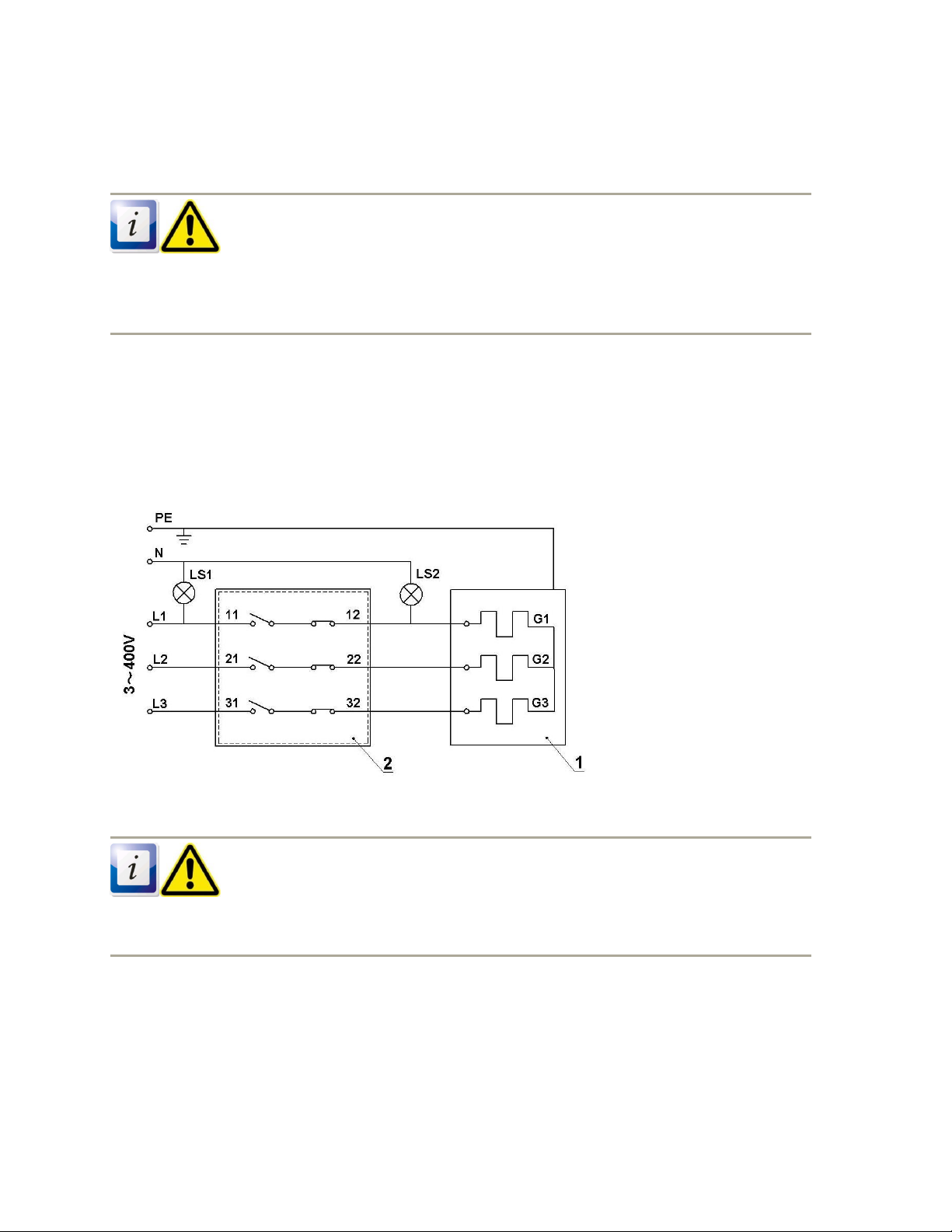
three-phase electric current of ~400 V. The wiring diagram of the heater is
presented in picture 2. It is recommended not to turn the heater on before filling the
tank up with water as it may cause damage to the heating elements and the
necessity of their replacement.
1- heating element
2 –thermostat with the
temperature switch regulator
LS1, LS2 –signaling lamps
Picture 2. The wiring diagram of the PANNEX DUO COMBI VVB 160L heater
Connecting to the power supply system may be performed only by a qualified
person.
Connecting to the circulation system
When the supplying sources are far away from the heater it is recommended to
use the circulating water connection pipe situated in the top end cap and. A
circulating pump should be installed on the circulation line and the pipes delivering
water to the supplying sources should be thermally insulated. In case there is no
circulation the connection pipe should be plugged.

ver.01/2 PANNEX DUO COMBI VVB 160L
7
Start up
After installation the heater must be filled up with water. In order to do that perform
the following:
–open one of the hot usable water supplying sources and the valve on the cold
water inlet to the heater (water-supply system)
–fill the tank up to the moment when water appears in the open hot usable water
supplying source and close the open hot usable water valve.
–check the tightness of the installed connection to the heater
–fill the heating water network, paying attention to deaeration of the coil pipe (it may
be performed by using a suitable circulating pump or a special vent installed on the
heating water inlet pipe)
–check the tightness of the connection between the heating network and the heater
–switch the central heating boiler on
After connecting to the wiring system and switching the electric supply on (the
green signalling lamp switches on) the desired temperature of water should be
adjusted with the use of the thermostat knob. When the heater is on, the red
signaling lamp is on. When the temperature of water reaches the required level the
thermostat switches off the heater and the lamp turns off.
Description of the heater knob settings:
1 - approx. 25°C
2 - approx. 50°C
3 - approx. 75°C
ECO - setting between 1 and 2 in which the tank was tested for energy class,
the most economical setting (approx. 45°C).
When the temperature exceeds 87°C the safety switch cuts off the power
supply to the electric heater. Before switching the power supply on again the
temperature must go down below 87°C and the safety switch must be reset by
pushing the button on the temperature limit control. In order to do that the power
must be shut off and the cover of the control panel must be removed.When the
power shut off performed by the safety switch happens too often it may indicate that
the thermostat or the temperature limit control is out of order and needs to be
replaced by a qualified person. To limit the risk of electric shock all the metal
elements of the heater are connected to the protection wire.
3. MAINTENANCE AND USAGE
Operation of the heater connected to a boiler
The temperature sensor which controls the work of the boiler supplying the
heating system of the heater should be placed in the thermometer pipe situated
under the cover of the control panel in the lid of the stub pipe of the bottom end cap.
To get access to the pipe the lower control panel or the insert should be removed. In
case of the heater with the electric heater there are also capillary pipes of the
thermostat and the temperature limit control in the pipe (when removing capillary
pipes violent twists of the cables connecting capillary pipes to the thermostat and
safety switch should be avoided)
Maintenance tips
1. The proper functioning of the safety valve should be checked periodically, at least
once a month and each time before first start-up after a period of shutdown.
2. During the work of the heater the magnesium anode rod slowly depletes so its
condition should be checked periodically, at least once every 18 months and it

ver.01/2 PANNEX DUO COMBI VVB 160L
8
should be replaced if necessary. It is recommended to replace the anode rod
every two years.
Magnesium anode rod replacement
The magnesium anode rod is situated in the top end cap of the tank and can be
accessed after the upper panel has been removed, picture 1.
To inspect or replace the anode rod perform the following:
–turn off the supply of the cold usable water and turn on the hot water using any of
the taps (the best one is the tap situated under the level of the top end cap of the
heater) in order to drain some amount of water out and reduce the overpressure in
the tank
–unscrew 4 positioning pins from upper panel and take it off
–remove the element of insulation that covers the insert with the attached anode rod
–using s60 socket wrench unscrew (1 ¼” twist) the plug together with the attached
anode rod
–screw the new anode rod with the insert in, paying attention to the tightness of the
connections (it is also advised to replace the seals)
The magnesium anode rod plays an important role in the process of the heater
maintenance as it protects the enameled tank against corrosion and its regular
inspection, replacement and proper installation are the conditions which
should be fulfilled in order to get the warranty of
Before performing any maintenance or repair works, please make sure that the
power supply to the heater is shut off.
4. WARRANTY TERMS AND CONDITIONS
1. The warranty of the enameled tank is valid for 60 months
2. The warranty of the other heating elements is valid for 24 months
3. The period of warranty is valid from the date of purchase. The date must be
specified in a Warranty Card and confirmed by a proof of purchase (receipt) written
and stamped by the vendor.
4. The guarantor guarantees a faultless operation of the heater on the condition that
it is installed and used in accordance with this Instructions for Use.

ver.01/2 PANNEX DUO COMBI VVB 160L
9
Zakład Urządzeń Grzewczych
„ELEKTROMET”
Gołuszowice 53
48-100 Głubczyce
tel. +48 / 077 / 485 65 40
DEKLARACJA ZGODNOŚCI
(DECLARATION OF CONFORMITY)
Pan Wojciech Jurkiewicz
(Mr) ……………………………………………………………………
(Imię, Nazwisko / Surname, Name)
reprezentujący firmę ZUG “ELEKTROMET” Gołuszowice 53 48-100 Głubczyce
(legal representative of) ……..……………………………………………………………
(Nazwa i adres producenta / Manufacturer’s Name and Address)
DEKLARUJE / DECLARES
z pełną odpowiedzialnością, że wyrób:
(with all responsibility, that the product):
Elektryczny pojemnościowy podgrzewacz wody użytkowej typu
PANNEX DUO COMBI VVB 160L
…………………………………………………………………………………………
(nazwa, typ lub model / name, type or model)
został zaprojektowany, wyprodukowany i wprowadzony na rynek zgodnie z następującymi
dyrektywami:
(has been designed, manufactured and placed on the market in conformity with directives):
-Dyrektywa Urządzeń Ciśnieniowych (PED): 2014/68/UE
-Pressure Equipment Directive (PED): 2014/68/UE
-Dyrektywa niskonapięciowa 2014/35/UE;
the safety principles of the “Low voltage” Directive 2014/35/UE
-Dyrektywa kompatybilności elektromagnetycznej “EMC” 2004/108/WE
the protection requirements of „EMC” Directive 2004/108/EC
-Dyrektywa Prostych Zbiorników Ciśnieniowych 2014/29/UE
- The Simple Pressure Vessels Directive 2014/29/UE
i niżej wymienionymi odpowiednimi normami:
and that the following relevant Standards:
- PN - EN 60335 - 1
- PN - EN 60335-2-21
- PN - EN 61000-3-2
- PN - EN 61000-3-3
- PN - EN 55014-1
Gołuszowice, 06. lipiec. 2017r.
…………………………………………………….….. …………………………………………………
(miejsce i data wystawienia) (imię i nazwisko oraz podpis)
(place and date) (Name, Surname and Signature)

ver.01/2 PANNEX DUO COMBI VVB 160L
10
ver.01/2 PANNEX DUO COMBI VVB 160L
11
ver.01/2 PANNEX DUO COMBI VVB 160L
12
Table of contents
Popular Water Heater manuals by other brands

andrews
andrews CSC39 Installation guide, operation & service manual

Bosch
Bosch Tronic 1000 T installation instructions

Zelmer
Zelmer CK2320 user manual

Radiantec
Radiantec Solar Water Heater owner's manual

STIEBEL ELTRON
STIEBEL ELTRON HSBB 180 Plus Operation and installation

STIEBEL ELTRON
STIEBEL ELTRON DEL 18 SLi Operating and installation instructions

STIEBEL ELTRON
STIEBEL ELTRON Accelera 300 OPERATING AND INSTALLATION Manual

Bradford White
Bradford White U65L155E N Series Service manual

Ariston
Ariston 45 Assembly and operation instructions

Air Venturi
Air Venturi EZ Fill system manual

Dux
Dux DN15DS Installation and owner's guide

Haier
Haier ES30V-A3 instruction manual


