Element SUM-C32 Quick setup guide

Jelement
SUM—C32
ASSEMBLY
&
USE
INSTRUCTIONS
4003091
3v.A

.CAUTION
/
INFORMATION
Make
sure
no
obstacles
are
in
the
desk's
path.
Make
sure
the
desktop
is
not
touching
any
walls.
Make
sure
all
cards
are
appropriate
length
to
accommodate
the
change
in
height.
Pinch
Point
Keep
hands
and
fingers
clear.
Keep
children
away
from
electric
height-adjustable
desks,
control
units
and
handsets.
There
is
a
risk
of
injury
and
electric
shock.
A
A
Keep
all
electrical
components
away
from
liquids.
A
Do
not
sit
or
stand
on
the
desk
frame.
A
A
Do
not
crawl
or
lie
under
the
desk
frame.
A
Do
not
open
any
of
the
components
-
the
Legs,
Control
Box,
or
Switch.
A
There
is
a
danger
of
electric
shock.
Do
not
place
any
obiects
taller
than
20'
underneath
the
desk.
A
This
product
is
designed
with
a
duty
cycle
of
10%
{2
min.
on,
I8
min.
off).
o
In
the
event
of
a
power
outage
or
if
the
power
cord
is
unplugged,
0
a
manual
reset
may
be
necessary
~
see
USE
section.
IUSE
/
LIABILITY
This
height
adiustable
desk
has
electric
motors
and
is
designed
for
use
in
dry
work
areas
only.
The
desk
height
is
adiustable
so
that
it
can
be
positioned
at
the
most
ergonomically
suitable
height.
Any
other
use
is
at
user's
risk.
Under
no
circumstances
does
the
manufacturer
accept
warranty
claims
or
liability
claims
for
damages
caused
from
improper
use
or
handling
of
the
desk
frame.
IMPORTANT:
Please
read
this
manual
carefully.
If
this
desk
is
sold,
please
provide
this
manual
to
the
buyer.

J-ASSEMBL
TOOLS
N"
4mm
Allen
Wrench
[included]
PARTS
LIST
EControl
Bax
Handset
a
Power
Cord
acoble
(1.3m)
Phillips
Head
Screwdriver
and/or
Power
Drill
Frame
End
A
Frame
End
B
Center
Rail
Side
Bracket
V
>2}:
Tape
Measure
EM8X25
Set
Screw
(preinstalled)
mex1
4
Machine
Screw
8
beM
cs
Machine
Screw
8
IEM5x2O
Wood
Screw
12
M5x16
Wood
Screw
4
Cable
Clip
10
e3-
.ASSEMBLY—
out
all
components
and
hardware
to
ensure
that
you
have
all
the
components
and
hardware
listed
on
the
pans
Page.
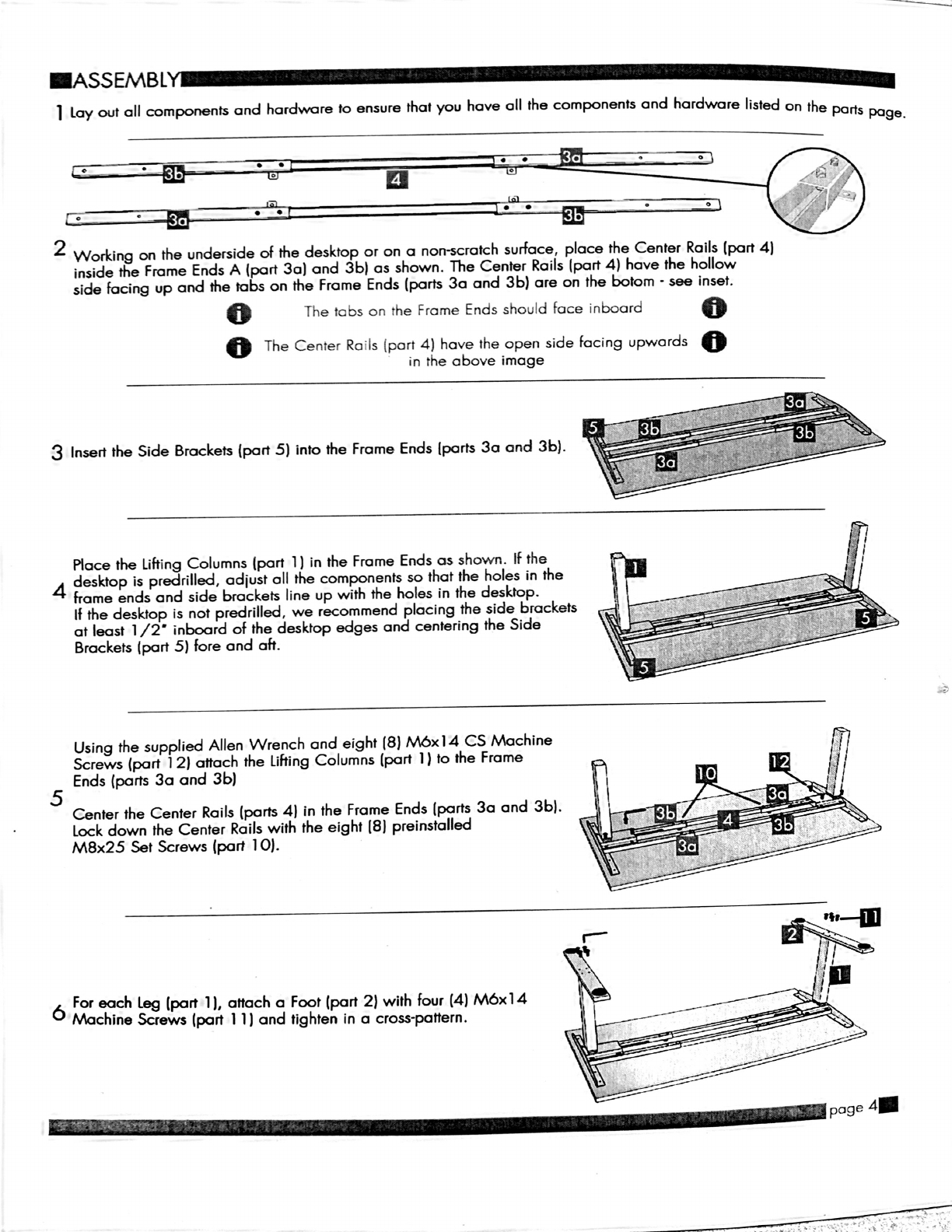
1
Lay
2
Working
on
the
underside
of
the
desktop
or
on
a
non-scratch
surface,
place
the
Center
Rails
[pan
4)
inside
the
Frame
Ends
A
(part
30)
and
3b)
as
shown.
The
Center
Rails (part
4)
have
the
hollow
side
facing
up
and
the
tabs
on
the
Frame
Ends
(parts
30
and
3b)
are
on
the
botom
-
see
inset.
o
The
tabs
on
the
Frame
Ends
should
face
inboard
o
o
The
Center
Rails (part
4)
have
the
open
side
facing
upwards
o
in
the
above
image
3
Insert
the
Side
Brackets
(part
5)
into
the
Frame
Ends
[parts
30
and
3b).
Place
the
Lifting
Columns
[part
1)
in
the
Frame
Ends
as
shown.
If
the
4
desktop
is
predrilled,
adiust
all
the
components
so
that
the
holes
in
the
home
ends
and
side
brackets
line
up
with
the
holes
in
the
desktop.
If
the
desktop
is
not
predrilled,
we
recommend
placing
the
side
brackets
at
least
1/2'
inboard
of
the
desktop
edges
and
centering
the
Side
Brackets
(part
5)
fore
and
aft.
Using
the
supplied
Allen
Wrench
and
eight
(8)
beIA
CS
Machine
Screws
(part
1
2)
attach
the
Lifting
Columns
(part
1)
to
the
Frame
Ends
(parts
30
and
3b)
5
Center
the
Center
Rails
(parts
4)
in
the
Frame
Ends
[parts
30
and
3b).
Lock
down
the
Center
Rails
with
the
eight
[8)
preinstalled
M8x25
Set
Screws
(part
)0).
6
For
each
Leg
[part
1),
attach
0
Foot
(part
2)
with
four
(4)
M6xl4
Machine
Screws
(part
I
I)
and
tighten
in
a
cross-pattern.
.ASSEMBL
Doublecheck
that
the
wood
screws
are
not
too
long
for
your
desktop
A
A
and
won’t
puncture
the
surface
when
screwed
all
the
way
in.
We
recommend
that
you
predrill
any
holes
needed
for
fasteners
o
it
your
desktop
is
not
pre-drilled.
Never
use
countersunk
screws.
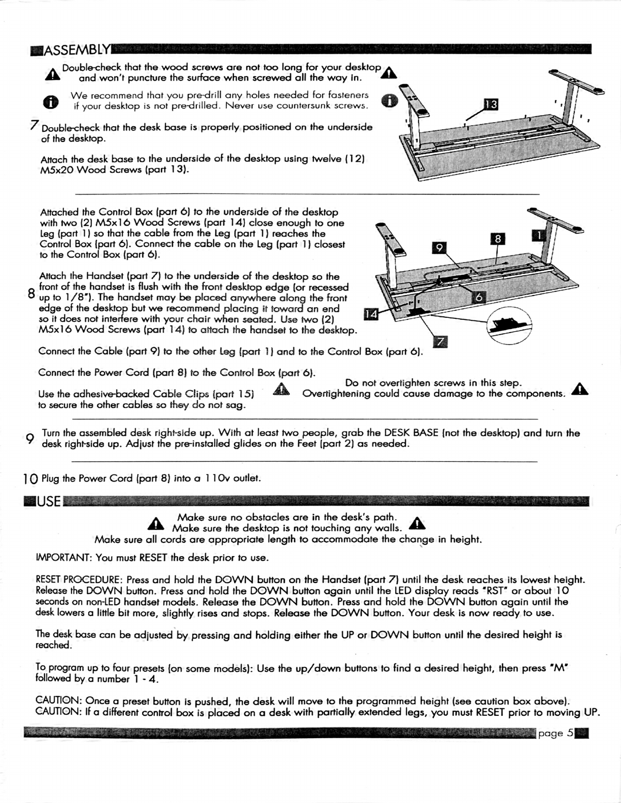
7
Double-check
that
the
desk
base
is
properly
positioned
on
the
underside
of
the
desktop.
Attach
the
desk
base
to
the
underside
of
the
desktop
using
twelve
(l
2)
M5x20
Wood
Screws
(part
13).
Attached
the
Control
Box
(part
6)
to
the
underside
of
the
desktop
with
two
(2)
leb
Wood
Screws
(part
)4)
close
enough
to
one
Leg
(part
i)
so
that
the
cable
from
the
Leg
(part
1)
reaches
the
Control
Box
[part
6).
Connect
the
cable
on
the
Leg
(part
1)
closest
to
the
Control
Box
(part
6).
Attach
the
Handset
(part
7)
to
the
underside
of
the
desktop
so
the
front
of
the
handset
is
flush
with
the
front
desktop
edge
(or
recessed
8
up
to
1/8").
The
handset
may
be
placed
anywhere
along
the
front
edge
of
the
desktrpo
but
we
recommend
placing
it
toward
an
end
so
it
does
not
inte
ere
with
your
chair
when
seated.
Use
two
(2)
M5xl
6
Wood
Screws
(part
14)
to
attach
the
handset
to
the
desktop.
Connect
the
Cable
(part
9)
to
the
other
Leg
{part
i)
and
to
the
Control
Box
(part
6).
Connect
the
Power
Cord
(part
8)
to
the
Control
Box
(part
6).
A
Do
not
overtighten
screws
in
this
step.
A
Use
the
adhesive-backed
Cable
Clips
[part
15)
Overtightening
could
cause
damage
to
the
components.
to
secure
the
other
cables
so
they
do
not
sag.
9
Turn
the
assembled
desk
right-side
up.
With
at
least
two
people,
grab
the
DESK
BASE
[not
the
desktop)
and
turn
the
desk
right-side
up.
Adiust
the
pre-installed
glides
on
the
Feet
[part
2)
as
needed.
I
0
Plug
the
Power
Cord
(part 8)
into
a
l
lOv
outlet.
A
Make
sure
no
obstacles
are
in
the
desk's
path.
A
Make
sure
the
desktop
is
not
touching
any
walls.
Make
sure
all
cards
are
appropriate
length
to
accommodate
the
change
in
height.
IMPORTANT:
You
must
RESET
the
desk
prior
to
use.
RESET
PROCEDURE:
Press
and
hold
the
DOWN
button
on
the
Handset
[part
7)
until
the
desk
reaches
its
lowest
height.
Release
the
DOWN
button.
Press
and
hold
the
DOWN
button
again
until
the
LED
display
reads
'RST'
or
about
10
seconds
on
non-LED
handset
models.
Release
the
DOWN
button.
Press
and
hold
the
DOWN
button
again
until
the
desk
lowers
a
little
bit
more,
slightly
rises
and
stops.
Release
the
DOWN
button.
Your
desk
is
now
ready
to
use.
The
hdedesk
base
can
be
adjusted
by
pressing
and
holding
either
the
UP
or
DOWN
button
until
the
desired
height
is
reac
.
To
program
up
to
tour
presets
(on
some
models):
Use
the
up/down
buttons
to
find
a
desired
height,
then
press
'M'
lollowed
by
a
number
1
-
4.
CAUTION:
Once
a
preset
button
is
pushed,
the
desk
will
move
to
the
programmed
height
(see
caution
box
above).
CAUTION:
It
a
different
control
box
is
placed
on
a
desk
with
partially
extended
legs,
you
must
RESET
prior
to
moving
UP.
.TROUBLE
SHOOTING
—
If
your
desk
is
not
functioning
properly
it
may
need
to
be
reset.
Follow
the
RESET
procedure
outlined
in
the
USE
section.
If
your
desk
has
a
handset
with
an
LED
readout
and
it
displays
'RST'
(reset),
perform
the
reset
procedure
outlined
in
the
USE
section.
If
the
LED
readout
displays
an
error
message
('Erl
'
-
'Er13')
confirm
that
all
wired
connections
are
secure
(legs
to
cables,
cables
to
control
box).
Then
perform
the
reset
procedure
outlined
in
the
USE
section.
If
the
error
message
persists
after
the
reset
procedure,
contact
your
seller.
If
the
height
between
the
legs
exceeds
1
.5
inches,
stop
the
reset
procedure
&
contact
your
seller.
If
the
handset
displays
'HOT',
let
the
base
cool
down
for 20
minutes.
.SPECIFICATIONS_
_
_______
_
.-=-.-
_________
“um
................
__
Heiht
Rane
26
.25-
46"
without
deskto
I
21
.5
~
47.8"
ithout
deskto
42'
min.
-
72"
max.
42"
min.
-
72'
max.
1.2"
er
secon
[no
ca]
1.5"
er
secon
'
(no
ea)
10%.
Max.
2
mins
on
18
mins
0
10%.Max.2
mins
on
18
mins
0
So
s_ta
rt
r
“Lush
-_
So
start
sto
A'usta
e
eve
in
stus
Ad'ustate
l__‘ev~e..'-i_&_’n
stus
4
Memory
presets
(some
m
e
s]
4
Memory
presets
lwme
moe
s)
.PROGRAMMING
Press
the
DOWN
button
on
the
Handset
(part
7)
until
the
base
reaches
its
lowest
position.
Press
and
hold
the
DOWN
button
again
until
the
LED
display
reads
'RST'.
Press
and
hold
the
1
button
(about
5
seconds}
while
the
LED
flashes
'RST'
and
then
switches
to
either:
l:l
El
l—
10.1
=
One-Touch
10.2
--
Constant-Touch
Release
the
1
button.
Press
the
1
button
again
until
the
desired
setting
is
reached.
Once
the
chosen
setting
is
displayed,
release
the
button
and
wait
about
5
seconds
for
the
display
to
return
to
'RST'.
Finish
the
reset
process
by
pressing
and
holding
the
DOWN
button
until
the
desk
lowers
a
little
bit
more,
slightly
rises
and
stops.
Release
the
button.
The
new
program
setting
is
saved
and
your
desk
is
now
ready
to
use.
.SETTING
THE
LED
RETRACTED
HEIGHT
(some
models)
Press
the
DOWN
button
on
the
Handset
[part
7)
until
the
base
reaches
its
lowest
position.
Measure
the
distance
from
floor
to
the
top
surface
of
the
desktop.
If
the
number
on
the
LED
display
does
NOT
match
your
measurement,
follow
these
steps:
Press
and
hold
the
DOWN
button
until
the
LED
display
reads
'RST'.
l:l
El
l—
Press
and
hold
the
'M'
button
[about
5
seconds)
until
the
LED
displays
the
flashing
height.
(If
the
display
returns
to
'RST'
before
the
next
step
is
taken,
repeat
this
step.)
Use
the
UP/DOWN
buttons
to
change
the
value
of
the
starting
height
so
that
it
matches
your
measurement.
Wait
about
5
seconds
and
the
display
will
return
to
'RST.’
Finish
the
reset
process
by
pressing
and
holding
the
DOWN
button
again
until
the
desk
lowers
a
little
bit
more,
slightly
rises
and
stops.
Release
the
button.
The
new
starting
height
value
is
saved
and
your
desk
is
now
ready
to
use.
Note:
the
LED
display
has
a
1:0,]
tolerance.

ISETTING
THE
UPPER
&
LOWER
LIMITS
This
base
is
designed
to
go
to
its
minimum
and
maximum
heights,
allowing
for
the
widest
possible
range.
It
you
prefer
to
change
the
settings
to
a
more
narrow
range,
follow
these
steps:
Make
sure
the
power
is
ON
and
a
number
reads
in
the
LED
display
[it
no
number
appears,
please
follow
the
Reset
procedure
described
in
the
USE
section).
To
Set
the
Upper-Limit
Position:
Use
the
UP/
DOWN
buttons
to
move
the
base
to
the
desired
maximum-height
position.
Press
the
'M'
button
and
release.
Press
the
UP
button
and
release.
The
LED
display
will
flash
'5
-".
Press
and
hold
the
'M'
button
[about
2
seconds)
until
the
LED
display
changes
to
'999'.
The
display
will
automatically
return
to
the
selected
height.
The
new
upper
limit
is
now
set.
To
Set
the
Lower-Limit
Position:
Use
the
UP/
DOWN
buttons
to
move
the
base
to
the
desired
minimum-height
position.
Press
the
'M'
button
and
release.
Press
the
DOWN
button
and
release.
The
LED
display
will
flash
'5
-".
Press
and
hold
the
'M'
button
(about
2
seconds)
until
the
LED
display
changes
to
'000'.
The
display
will
automatically
return
to
the
selected
height.
The
new
lower
limit
is
now
set.
To
Remove
the
Upper/
Lower
Limit
Positions:
Press
the
'M'
button
and
release.
The
LED
display
will
flash
'5
-'.
Within
5
seconds,
press
the
'M'
button
again
and
hold
for
2
seconds.The
LED
display
will
change
to
'555’
and
then
automatically
return
to
the
height
display.
The
upper
and
lower
limits
are
now
removed.
A
A
RESET
procedure
requires
the
desk
base
to
full
retract
[beyond
any
lower
limit
set).
A
Please
ensure
that
you
have
the
proper
clearance
below
the
desk
base.
After
the
upper
and
lower
limits
are
set,
the
previous
memory
positions
[1
,
2,
3,
4)
may
be
outside
the
new
range
of
movement.
If
so,
simply
reset
the
memory
positions.
It
you
attempt
to
revise
a
previously
set
upper
or
lower
limit
and
it
is
outside
of
the
existing
range,
you
will
need
to
remove
the
previously
set
upper/
lower
limits
first.
IHANDSET
LOCK
(some
models)
To
lock
the
handset:
Press
and
hold
the
'M'
button
[about
8
seconds)
until
the
LED
display
switches
to
'S
-'
and
then
to
'LOC."
Release
the
button.
To
unlock
the
handset:
Press
and
hold
the
'M'
button
[about
8
seconds)
until
the
LED
switches
from
'LOC'
to
the
height
display.
Release
the
button.
.CHANGING
INCHES
TO
CENTIMETERS
lsome
models)“
-
Press
the
DOWN
button
on
the
Handset
(part
7)
until
the
base
reaches
its
lowest
position.
Press
and
hold
the
DOWN
button
again
until
the
LED
display
reads
'RST'.
H
E
'—
Press
and
hold
the
2
button
(about
5
seconds)
while
the
LED
flashes
'RST'
and
then
switches
to
either:
l0.3
—-
cm
l0.4
=
inches
Release
the
2
button.
Press
and
hold
the
2
button
again
until
the
desired
setting
is
reached.
Once
the
chosen
setting
is
displayed,
release
the
button
and
wait
about
5
seconds
for
the
display
to
return
to
'RST'.
'Finish
the
reset
process
by
pressing
and
holding
the
DOWN
button
until
the
desk
lowers
a
little
bit
more,
slightly
rises
and
stops.
Release
the
button.
The
new
measurement
setting
is
saved
and
your
desk
is
now
ready
to
use.

Jéelement
1
17937
NE
Sandy
Blvd.
Portland,
OR
97230
tel:
503.476.1616
www.elementcontract.com
,
.
_
.
_____.....H...‘.....-._
.——u——_.‘....._..‘.
Table of contents
Other Element Indoor Furnishing manuals

Popular Indoor Furnishing manuals by other brands

Emmezeta
Emmezeta HILS925E1 Assembling Instruction

Kvik
Kvik MDBU4800,060 Assembly instruction

Lightolier
Lightolier RGB-1 specification

Naomi Home
Naomi Home Ariel Executive L-Shaped Desk Assembly instructions

Flexa
Flexa 80-31506-95 Assembly instructions and directions for use

Gami
Gami G11-S'COOL 160 Assembly instructions


Elite Industries
Elite Industries EL-785 Assembly instructions

Bouclair
Bouclair 9400935 Assembly instructions

7th Haven
7th Haven 7HAC0004 Assembly instructions

Naterial
Naterial DUO WICKER 3276007298734 Assemby - Use - Maintenance Manual

Ostermann
Ostermann REDOCOL e-Desk Pro 90 Assembly & operation manual

3branch
3branch KURVE Assembly instructions