Elenos T30000 User manual

BROADCAST EQUIPMENT
Via G. Amendola 9
44028 Poggio Renatico
Ferrara - Italy
Tel : +39 532 829 965
Fax : +39 532 829 177
E-mail: [email protected]
Web Site: http://www.elenos.com

Hand Book T30000 - 2
Technical Office TEL: +39 532 829 965 FAX: +39 532 829 177
The constructor reserves the right to modify the information in this manual at any time
without advising update.
2000 Elenos S.r.l.
Printed in Italy
Cod. MAN0035
21/10/1996 Preliminary mater in English
23/10/2000 Rev. 1
01/05/2001 Rev. 2

Hand Book T30000 - 3
Technical Office TEL: +39 532 829 965 FAX: +39 532 829 177

Hand Book T30000 - 4
Technical Office TEL: +39 532 829 965 FAX: +39 532 829 177
SUMMARY
DESCRIPTION............................................................................................................... 6
TECHNICAL FEATURES............................................................................................ 8
TECHNICAL DESCRIPTION ..................................................................................... 9
USER INTERFACE AND LOGIC OF OPERATION.............................................. 10
FRONT PANEL ............................................................................................................ 14
FIRST PHASE OF INSTALLATION ........................................................................ 15
INSTALLATION OF THE THERMIONIC TUBE.................................................. 18
SECOND PHASE OF INSTALLATION ................................................................... 19
ACTIVATION OF THE TRANSMISSION SYSTEM ............................................. 20
TUNING INSTRUCTIONS ......................................................................................... 21
OPERATIONAL LIMITS ........................................................................................... 23
PERIODIC MAINTENANCE..................................................................................... 24
ADJUSTMENT OF THE FILAMENT VOLTAGE ................................................. 25
REMARKS ON ELECTRICAL DIAGRAMS .......................................................... 26
LINE VOLTAGE DIAGRAM CONNECTION ........................................................ 27
PART LIST TRANSMITTER 20K............................................................................. 28
Sheet # 1.......................................................................................................................29
Part list of Sheet # 1 ..................................................................................................... 30
Sheet # 2.......................................................................................................................31
Part list of Sheet # 2 ..................................................................................................... 32
Sheet # 3......................................................................................................................33
Part list sheet # 3 .......................................................................................................... 34
Sheet # 4.......................................................................................................................35
Part list sheet # 4 .......................................................................................................... 36
Sheet # 5.......................................................................................................................37
Part list sheet # 5 .......................................................................................................... 38
Sheet # 6.......................................................................................................................39
Part list sheet # 6 .......................................................................................................... 40
Sheet # 7.......................................................................................................................41
Part list Sheet # 7 ......................................................................................................... 42
Layout E20123.3 ......................................................................................................... 43
Electrical diagram E20123.3....................................................................................... 44
Part list E20123.3......................................................................................................... 45
Layout E20127 ............................................................................................................ 46

Hand Book T30000 - 5
Technical Office TEL: +39 532 829 965 FAX: +39 532 829 177
Electrical diagram E20127 ( 1 of 6)............................................................................ 47
Part list E20127............................................................................................................ 53
Layout E20128 ............................................................................................................. 62
Electric diagram E20128.............................................................................................. 63
Part list E20128............................................................................................................ 64
Layout E20131 ............................................................................................................. 65
Electric diagram E20131.............................................................................................. 66
Part list E20131............................................................................................................ 67
E20138 ......................................................................................................................... 69
Part list E20138............................................................................................................ 70
E20144 ......................................................................................................................... 71
E20139 ......................................................................................................................... 72
Part list E20139............................................................................................................ 73

Hand Book T30000 - 6
Technical Office TEL: +39 532 829 965 FAX: +39 532 829 177
DESCRIPTION
The T30000 is an amplifier for the transmission of frequency modulation (total deviation 150 KHz) using
a thermionic tube in an amplifying cavity with adjustable input and output frequency tuning.
Conceived as the final stage in a transmission system, it requires a modulator and other intermediate
stages of amplification housed in the same or separate mechanical structure.

Hand Book T30000 - 7
Technical Office TEL: +39 532 829 965 FAX: +39 532 829 177

Hand Book T30000 - 8
Technical Office TEL: +39 532 829 965 FAX: +39 532 829 177
TECHNICAL FEATURES
DESCRIPTION 10000W OUT 30000W OUT
THERMOIONICS TUBE TYPE TRIODE EIMAC 3CX20000
POWER OUTPUT MAX 30000 WATT
EXCITATION POWER 650W 1850W
REFLECTED POWER 750W 300W
S.W.R. MAX 750 WATT
POWER GAIN 12 dB
R.F. HARMONIC COMPONENT MIN -82 dBC
SYNCHRONOUS A.M. 0.2 %
HIGH TENSION TYP V.HT.=9500V
ANODE EFFICENCY 70% 75%
ANODE CURRENT {IA} TYP 1.9A 4.5A
ANODE CURRENT {IA} MAX 4.8A
GRID CURRENT {IG} TYP 200 mA 500 mA
GRID CURRENT {IG} MAX 1A
BIAS VOLTAGE TYP V.BIAS=35-230V
FILAMENT VOLTAGE range V.FIL.=6.1-6.4V
R.F. CAVITY TEMPERATURE TYP 70 °C
R.F. CAVITY TEMPERATURE MAX 95 °C
INSTALLATION ALTITUDE MAX 3000 mt. on sea level
AMBIENT HUMIDITY MAX 90 %
OPERATING TEMPERATURE range 0°C-45°C
INPUT CONNECTIONS 50 OHM 7/8” TYPE CONNECTOR
OUTPUT CONNECTIONS 50 OHM 3+1/8” TYPE CONNECTOR
STAR TYPE SUPPLY 3x380V + N
GENERAL POWER SUPPLY MAX 16.5 KVA 65 KVA
POWER FACTOR COS § = 0.9

Hand Book T30000 - 9
Technical Office TEL: +39 532 829 965 FAX: +39 532 829 177
TECHNICAL DESCRIPTION
The T30000 unit is composed of various functional elements: power amplifying cavity which houses the
thermionic tube, (this is a triode with direct cathode heating, configured in common grid mode with
input signal to the cathode and output from the anode); low-pass output filter for the suppression of
harmonic components of the carrier frequency; analog filter connected to the input circuit; three phase
high voltage power supply for the thermionic tube's anode; cathode bias circuit; AC stabilised power
supply circuit for the filament/cathode; safety circuits for the protection of the unit and service
personnel; power supply for the motors which control the amplifying cavity's tuning. The unit is
designed to function with the thermionic tube at full power in class C mode, at lower powers in class B
and very low powers in class AB. The cathode bias circuit (see card E20123.x) is automatic and senses
cathode current. The cathode/grid voltage is obtained via a chain of power diodes connected in series
with each other. The very high voltage gain of the thermionic tube allows the class of amplification to
be changed with small changes in bias voltage. The tube filament AC supply is kept constant by a
phase-angle switching power supply with stability of better than 1.5% (see cards E20127.x and
E20128.x). Activation of the filament power supply is conditional upon the pressure of cooling air
within the amplifying cavity; if regular, the filament supply is enabled. The working voltage is reached
progressively to avoid overcurrent to the tube's socket. A regulator circuit is available on card
E20127.x which allows the filament voltage/power to be varied in order to extend the life of the
thermionic tube if the RF power required is less than the nominal value (see technical notes on the
filament). The high voltage anode power supply (7500 volts DC) is generated by a six phase rectifier
(see card E20144.x) with an inductive filter followed by a capacitive filter. A high power, insulated
resistor is connected in series with the tube's anode supply output in order to limit the energy
dissipated in the event of accidental electric arc within the amplifying cavity or the thermionic tube.
The high power transformer is inserted electrically in 2 steps, the first connects a series resistor to limit
overcurrent, the second connects the transformer directly to the line supply. This avoids inadvertent
power loss due to the action of the local supply's safety cut-outs. The principal electronic circuit card
(E20127.x) contains all the user interface circuits (see also card E20131.x) and the circuits which
monitor all the important variables of the amplifier. Control of the unit includes the facility to disable
operation in the event of variables exceeding their safety limits, with various automatic reset modes.
For a detailed description of the unit's protection logic, consult the chapter entitled "user interface".
The low-pass output filter is housed within the unit, above the amplifying cavity. It is essential that
this filter is both connected and functioning perfectly; in case of malfunction it is not possible to
guarantee the suppression of spurious, out-of-band RF frequencies and, furthermore, dangerous
internal overheating of the equipment may be caused. The control of the RF tuning of the cavity is
performed by 2-speed electric motors. This technique , besides being convenient, ensures the safety of
personnel responsible for tuning the equipment. There are two amplifier cavity adjustment controls for
the input and two for the output; one of the two matches impedance, the other tunes the frequency.

Hand Book T30000 - 10
Technical Office TEL: +39 532 829 965 FAX: +39 532 829 177
USER INTERFACE AND LOGIC OF OPERATION
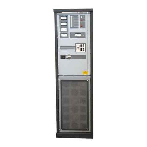
The display of all controls and operational parameters are situated on the unit's front panel. Any
suspension of operation, whether temporary or indefinite, results in the thermionic tube's HT anode
supply being shut down and the disabling of the modulator's supply. The shutting down of the
equipment as a result of a fault condition will be refer hereafter as the protection state. The most
frequent causes of each anomaly indicated are also displayed, assuming the unit is not faulty.
Four of the five meters simultaneously display the following operational parameters:
1) the RF power output (P.W.R.) 25KW f.s.d.
2) the reflected RF power present at the radiating system connector (S.W.R.), 2.5KW f.s.d.
3) the thermionic tube's anode current (I.A.) 5A f.s.d.
4) the thermionic tube's grid control current (I.G.) 2A f.s.d.
The fifth meter (TEST) can be switched to five different functions via a rotary selector switch situated
above it:
1) (V.C.) calibration of all meters. With the selector in this position, all the meters will display full
scale deflection (f.s.d.) to allow the operator to calibrate the scales and identify a faulty meter.
Adjustment of the meters is via 5 pre-set potentiometers located on the card E20131.x behind the
front panel (see circuit diagrams).
2) (V.HT) selects the reading of the anode supply voltage, 10KV f.s.d. DC.
3) (V.BIAS) selects the reading of the cathode/grid bias voltage of the thermionic tube, 200Vdc f.s.d.
4) (C.AIR) selects the reading of the temperature of the amplifying cavity's hot air exit, 100°C f.s.d.
5) (V.F.) selects the reading of filament voltage, 10V f.s.d. AC
The lever switch located above the rotary selector, described above, allows operation to be suspended by
the operator (ST.BY) or restored (H.T.). In the ST.BY position, the thermionic tube's anode voltage is
removed and the modulators supply is cut as in a "protection state".
The ST.BY indicator light identifies the position of the switch described above.
The RESET switch allows the operator to disable the automatic shutdown of the transmitter which follows
when the maximum number of automatic resets has been reached (8) for various parameters being
monitored: reflected power, anode current, grid control current and amplifier cavity cooling air exit
temperature. The number of resets that have taken place is displayed on the front panel alphanumeric
display (PROTECTION COUNTER). When the electronic logic has reached the limit of automatic
resets permitted, the unit will shutdown indefinitely and the front panel LOCK indicator will light. The
attempts at automatic reset are cumulative and will increment the counter even if they result from
different causes.

Hand Book T30000 - 11
Technical Office TEL: +39 532 829 965 FAX: +39 532 829 177
The ON indicator light indicates that the T30000 is powered by the line supply.
The flashing SAFETY light indicates that the equipment is not in a safe condition to operate at high
voltage and is thus in a protection state. This happens when a panel is open or an important electrical
connector is not inserted correctly.
The IA MAX indicator indicates that the maximum permitted anode current (3.3A) has been exceeded.
The amplifier is in the protection state. The protection logic attempts a reset after about 3 seconds and
increments the counter. The most probable causes of this anomaly are an excessive demand of RF
power from the output, or incorrect tuning (the impedance seen by the anode circuits is too low). If the
impedance of the radiating system is incorrect or unstable it is possible that large fluctuations of anode
current will be experienced with likely intervention of the protection mechanism. Variations of line
voltage will have an significant influence on anode current if the preceding RF stages maintain stable
power levels; in particular if the line voltage reduces but the excitation power remains unchanged,
anode current will increase appreciably. When the thermionic tube is at the end of its life, it is possible
for this fault to occur often.
The flashing IG MAX light indicates that the maximum permitted grid current (1A) has been exceeded.
The amplifier is in the protection state. The protection logic attempts a reset after about 3 seconds and
increments the counter. The most probable causes of this anomaly are an excessive RF power input, or
incorrect tuning (the impedance seen by the anode circuits is too high). If the impedance of the
radiating system is incorrect or unstable it is possible that large fluctuations of grid current will be
experienced with likely intervention of the protection mechanism. Variations of line voltage will have
an significant influence on grid current if the preceding RF stages maintain stable power levels; in
particular if the line voltage reduces but the excitation power remains unchanged, grid current will
increase appreciably. When the thermionic tube is at the end of its life, it is possible for this fault to
occur often, with problems of matching RF impedance with preceding stages.
The flashing SWR MAX light indicates that the maximum permitted reflected power (750W) at the power
output connector has been exceeded. The amplifier is in the protection state. The protection logic
attempts a reset after about 3 seconds and increments the counter. The most probable cause of this
anomaly is an incorrect value of impedance of the radiating system connected to the output of the
transmitter. Very often the cause of the protection state can seem inexplicable; this can occur when
there is a temporary collapse of the radiating system without permanent damage.
The flashing TEMP MAX light indicates that the maximum permitted temperature (85°C) of the hot air
output from the amplifying cavity has been exceeded. The amplifier is in the protection state. The
protection logic attempts a reset when normal temperatures have been restored and increments the
counter. The most probable causes of this anomaly are excessive ambient temperatures, inefficient air
filters or incorrect tuning (the impedance seen by the anode circuits is too high).
The flashing TRANS. OVERHEAT light indicates that the anode power supply transformer is
overheating. The amplifier is in the protection state. The protection logic attempts a reset when the

Hand Book T30000 - 12
Technical Office TEL: +39 532 829 965 FAX: +39 532 829 177
transformer sensor detects that normal temperatures have been restored. The most probable causes of
this anomaly are excessive ambient temperatures, or inefficient air filters.
The flashing UNDER PRESSURE light indicates that the pressure of cooling air within the amplifying
cavity is insufficient. The amplifier is in the protection state. The protection logic attempts a reset
when the pressure sensor detects that normal pressures have been restored. In this protection state, the
power amplifier will disable the filament supply as indicated by the ERRATIC VF light. The principle
cause of this fault is the inefficient condition of the cooling air filters or an insufficient circulation of
air in the room where the equipment is located. When the cooling fan is damaged or not incorrectly
powered, this protection state can arise sporadically.
The flashing ERRATIC VF light indicates that the filament voltage at the thermionic tube's socket is
incorrect. The amplifier is in the protection state. The protection logic resets operation when the value
returns to within a 5% tolerance. In the first phase of switching on, it is normal for this indication to
remain lit for up to ten seconds; this is due to the time taken for the filament power supply to reach its
operating value. This indication remains active if the UNDER PRESSURE indicator is lit at the same
time. When the filament voltage is at normal levels, the timer is activated to ensure a period of 300-
400 seconds elapses before the anode supply and the RF EXCITER supply are restored. In the event of
a loss of power lasting more than 1.5 seconds, the protection logic puts the transmitter into the
ERRATIC VF protection state and repeats the preheating cycle (TIMER ACTIVITY) before restoring
normal operation. The principle causes of anomalies can be related to problems of air pressure within
the amplifying cavity (see relevant paragraph) or caused by brief losses of power from the line supply.
The flashing ERRATIC T.P. LINE light indicates that the protection mechanism connected to the anode
power supply has intervened. The amplifier is in the protection state. The protection logic will not
automatically reset the unit; operator intervention is necessary. The principal causes of this anomaly
are short circuits, temporary or permanent, to any part of the anode supply circuit or chassis. In many
cases, it is a sign that the thermionic tube is at the end of its life or defective. Another cause of this
fault is high line voltage or an unbalanced three phase supply.
The flashing FAN PROTECTION light indicates that the protection mechanism connected to the main
amplifying cavity cooling fan has intervened. The amplifier is in the protection state. The protection
logic will not automatically reset the unit; operator intervention is necessary. The principal cause of
this fault is high line voltage or an unbalanced three phase supply.
The flashing ERRATIC BIAS light indicates that the cathode/grid bias voltage is incorrect. The amplifier
is in the protection state. The protection logic will not automatically reset the unit; operator
intervention is necessary: the only way to clear this fault and its effect is to remove electrical power
from the unit for at least ten seconds. The principal causes of this anomaly are short circuits,
temporary or permanent, to any part of the anode or cathode supply circuit or chassis. In many cases, it
is a sign that the thermionic tube is at the end of its life or defective.
The TIMER ACTIVITY light indicates that the timer is counting down during the pre-heating phase
required by the filament before the anode supply is enabled and RF excitation is applied to the input.

Hand Book T30000 - 13
Technical Office TEL: +39 532 829 965 FAX: +39 532 829 177
The amplifier is in the protection state even if no malfunction is present. When the timer has finished
its count, the indicator light goes out. Consult the paragraphs regarding ERRATIC VF, HT1 and HT2.
The HT1 light indicates when the TIMER ACTIVITY cycle has ended, but only if the unit is not in the
protection state due to any fault. This light indicates the first step of activating the anode power supply
at which point the transformer is connected to the line supply via a series resistance to limit
overcurrent. This phase is always followed, after about a second, by a second and final phase when the
HT2 indicator is lit. HT1 remains lit even when HT2 is lit. In this final phase, the unit is fully
activated: the anode transformer is connected directly to the line supply and the interlock enables the
modulator. The modulator is enabled if both indicators, HT1 and HT2 are lit; furthermore, both these
must be permanently lit when the transmission system is ready to go on-air. They will be extinguished
when the T30000 power stage is faulty or has been shutdown by the operator.
An hour counter is located on the front panel which registers the number of hours that the unit has been
connected to the line supply. This provides useful information for the purpose of periodic
maintenance.
A switch on the front panel controls the supply of power to all the internal circuits of the amplifier.
WARNING! The entire transmission system MUST BE DISCONNECTED from the line supply
before any internal work is carried out.
Actuators located on the front panel allow adjustment of tuning of the amplifying cavity (see chapter on
tuning adjustments). The three position key: FAST, LOCK and SLOW allows selection of the most
suitable motor speed for tuning. In the LOCK position all motors are inactive. Moving the key to the
FAST position selects a fast adjustment speed. SLOW provides a fine adjustment speed. The four 2-
position switches activate the motors for tuning the amplifying cavity and have the following
functions:
1) ANODE IMPEDANCE (top left). Adjusts the matching impedance between the thermionic tube's
anode and the radiating system. When pushed up, the anode impedance is increased and vice versa.
2) ANODE TUNING (top right). Adjusts the tuned frequency of the anode output circuit. When pushed
up the tuned frequency increases and vice versa.
3) INPUT IMPEDANCE (bottom left). Adjusts the matching impedance between the thermionic tube's
cathode and the exciter stage. When pushed up the impedance is increased and vice versa.
4) INPUT TUNING (bottom right) Adjusts the tuned frequency of the cathode input circuit. When pushed
up the tuned frequency increases and vice versa.

Hand Book T30000 - 14
Technical Office TEL: +39 532 829 965 FAX: +39 532 829 177
FRONT PANEL

Hand Book T30000 - 15
Technical Office TEL: +39 532 829 965 FAX: +39 532 829 177
FIRST PHASE OF INSTALLATION
Before describing the operational phases of the installation procedure, an indication of the ambiental
requirements of the location where the equipment is to be installed will be given. In the room
designated for installation, a means of removing the hot air generated by all the equipment should be
fitted. If the T30000 is the largest source of heat of the entire system, and if the ambient temperature is
25°C, at least 2000m³ per hour should be removed. If the temperature is 45°C then at least 3000m³ per
hour should be evacuated. Clearly, it is necessary to provide an equal amount of fresh air from outside
which must be filtered appropriately to avoid ingress of insects, dust, smoke and organic material. The
equipment can function normally at ambient temperatures between -5 and 45°C with a relative
humidity of 95%, non-condensing at 45°C. The line supply should be three phase with a voltage of
208/240 volts for delta connection (without neutral) and 380/415 volts for star connection (with
neutral). The power required to supply the T30000 is at least 24 KVA, taking account of the power
factor produced by the powerful anode rectifier. An efficient earth system must be provided to cater
for loss of current that can involve the chassis of the unit and other equipment in contact. Particular
attention should be paid to the connection with the radiating system which is especially prone to
electrical atmospheric phenomena. Before the antenna cable is fed to any enclosed space, an electrical
conductor with a section of at least 150mm² must be connected from the external conductor of the
antenna cable to a low impedance earth point dedicated to the antenna structure. Given the very low
values of parasitic inductance of the connections to the T30000, the amount of electrical energy of
atmospheric origin can only be partially controlled, in terms of personal safety, by earth connections.
To maximise safety of personnel, it is very important that the equipment is installed in a room which is
only entered by personnel on a temporary basis for reasons of maintenance, repairs or short checks. If
the installation room is entered frequently by personnel for reasons other than occasional service
operations on the transmitter, it is imperative that a metal grid, connected to an efficient earth, is used
to enclose the equipment in order to isolate it from the personnel. Having taken account of the
precautions previously detailed, the installation phase may now proceed. Remove all packing pieces
from the equipment used for transport and take care not to mislay any items included. Remove the
anode supply transformer from its transport case, taking care not to damage its windings and
connection terminals. Open all the equipment's panels and check the integrity of electrical connections
and the mechanical components of the RF connections; if any damage has been incurred in transit,
contact ELENOS for information regarding the guarantee. Remove the fixing bracket of the anode
power supply inductor which is no longer required for transport and is now dangerous!
Locate the rectangular plastic PVC tablet, supplied with the equipment, within the unit and place the
anode transformer on top, in the place clearly intended. The transformer is not fixed with bolts inside
the unit to avoid extra currents flowing between its external parts and the base of the equipment in
which it is located. Should the installation be made in seismic zones, the transformer should be lashed
to the internal structure of the unit using cord made of insulating material. The external body of the
transformer MUST be connected to the electrical earth of the unit, AT ONE POINT ONLY of its

Hand Book T30000 - 16
Technical Office TEL: +39 532 829 965 FAX: +39 532 829 177
body. Make absolutely certain that this earth conductor is connected to the earth terminal of the whole
T30000 unit. Do not connect the central node of the star of the transformer primary to the neutral of
the line supply. Connect the anode transformer primary to the intended, heavy-section cables with the
terminals best suited for high voltage operation (see the diagram for three-phase connection). Connect
the anode transformer secondary to the intended, heavily insulated cable (see identification labels).
Connect the two wires from the front, right-hand spar (see identification labels) to the thermal probe
socket of the anode transformer. WARNING! Malfunctions occuring during the first few hours of
operation are frequently caused by the passage of connection cables, using ordinary insulation, close to
parts of the anode transformer which present a risk. Take care to prevent loose cables from making
contact with the high voltage terminals of the anode transformer. The T30000 can be connected in two
ways to the line supply: star connection for line voltages of 380/415V with neutral connection (4 wire
+ earth); delta connection for line voltages of 208/240V without neutral connection (3wire + earth).
The entry for the main electrical supply cables is located on the rear of the unit where a series of holes
are available for the cables to enter. Inside the unit, near the two high-power contactors, a terminal
block is provided for the connection of the electrical supply cables. The section of the cables is
different for the two types of connection and can be determined from the technical table defining
values of current absorption of the line supply. Each country has its regulations concerning the section
of cable connected to the line supply which MUST be respected. In the absence of precise indications
the section of cable should allow for a current density of not greater than 4A per square millimetre of
conductor. (for example: a 50A current will require a cable of section of 50/4 = 12.5mm²). In the event
of a three phase star connection, do not swap the neutral line for any of the phases; this will do
permanent damage to the equipment. The neutral terminal can be readily identified by its label inside
the unit. For delta connection do not connect neutral to the terminal inside the unit; this has been
intentionally short-circuited to one of the three phases. IT IS ESSENTIAL THAT THE EQUIPMENT
IS CONNECTED TO THE EARTHING POINT of the system on site. Inside the unit is a terminal
which can be identified by its yellow/green colours; its dimension is the same as those of the three
phases. The earth connection is essential to ensure the safety of personnel who have occasion to make
physical contact with the apparatus or any mechanical structure or electrical conductor which are in
electrical contact with the apparatus. The earth connection is useful for minimising damage to the
equipment or other nearby equipment, in the event of high voltage discharges of an atmospheric
nature, or caused by the equipment itself. Connection to the three phases is NOT arbitrary and
determines the direction of rotation of the fan, which clearly must be correct. Testing for correct
rotation of the cooling fan must only be performed once the unit is fully closed to ensure operator
safety.

Hand Book T30000 - 17
Technical Office TEL: +39 532 829 965 FAX: +39 532 829 177
The electrical supply system which supplies the unit and all other equipment with power, MUST be fitted
with a CIRCUIT BREAKER with a current calibration not greater than 30% of the current drawn by
the whole transmitter. When the equipment is connected to the electrical supply, it exposes personnel
to the risk of coming into contact with high voltage lines; for this reason it is ABSOLUTELY
ESSENTIAL THAT THE CIRCUIT BREAKER IS IN THE OFF POSITION, whilst any equipment
panel remains open. Maintaining the unit's on/off switch in the off position IS NOT SUFFICIENT!
DO NOT SUPPLY ELECTRICAL POWER TO THE EQUIPMENT UNTIL ALL PANELS ARE
SHUT AND IT IS CONNECTED TO AN EARTHING POINT. An isolating transformer between the
equipment and the line supply significantly reduces the incidence of damage incurred by atmospheric
causes, greatly increases reliability and reduces the costs of faults caused by overvoltage of the line
supply. It is useful to construct a winding of about 25 turns, diameter 25-35 cm (about 1 foot) with the
line supply cables of the 3 phases and neutral before they enter the equipment. UNDER NO
CIRCUMSTANCES CONSTRUCT A WINDING WITH THE EARTH CABLE WHICH MUST BE
OF HEAVY SECTION (100mm²) AND MUST CONNECT THE EQUIPMENT TO EARTH
DIRECTLY AND WITH THE SHORTEST POSSIBLE LENGTH. The final power apparatus is
always connected to other excitation equipment which, in the majority of cases, comprises one or more
intermediate driver stages and an FM "exciter" modulator. The connections to the preceding
amplification stages and the modulator are of two types: radio frequency connections and electrical
line supply connections with a safety interlock system. The RF connections are as follows: the RF
output of the modulator is connected to the RF input of the first intermediate stage; the RF output of
the first intermediate stage is connected to the RF input of any second intermediate stage. The RF
output of the unit preceding the final T30000 amplifier is connected to the input of the low-pass filter
which finally supplies the input of the final amplifying cavity. The RF connection is complete when
the power output of the T30000 is connected to the radiating system. Connection to the radiating
system will determine the final positioning of the equipment which, for convenience, ought to be left
free until the final phase of installation. The connection of the electrical supply is more complex and
can vary according to the configuration of the transmission system components. For this reason a
series of diagrams has been supplied (see the reciprocal safety interlock connections between units)
which illustrates how the installation connections of all the equipment can be completed. Note that the
T30000 does not supply electrical power but only disconnects it via an interlock switch with a 10A
capacity. The connection scheme must satisfy two crucial constraints: if either the final power stage or
an intermediate stage fall into the protection state, the modulator must shutdown the RF output.

Hand Book T30000 - 18
Technical Office TEL: +39 532 829 965 FAX: +39 532 829 177
INSTALLATION OF THE THERMIONIC TUBE
When the T30000 amplifier is in its final position, installation of the thermionic tube may proceed. The
directions which follow are also valid for periodic replacement of the thermionic tube; for this reason
it is a good idea to leave a copy of the technical manual available nearby. The electrical circuit breaker
supplying the whole transmission system must be open before performing this operation so that the
system is ISOLATED from electrical power. The T30000 must also be ISOLATED from the radiating
system. WARNING! During the installation of the thermionic tube, the hands of the operator will be in
physical contact with parts normally functioning at HIGH VOLTAGE. Even if the equipment has been
inactive for some time, it is ESSENTIAL that a conductor be used to electrically connect the high
voltage supply to the chassis of the unit. WARNING! In order to discharge the high voltage capacitor,
connect the solid conductor to the unit's chassis at the point INTENDED for this operation: the
electrical junction connecting the overcurrent-limiting series power resistor with the anode of the
thermionic tube. If the high voltage capacitor is discharged at a point other than that previously
described, it is possible to cause permanent damage to the equipment. Remove the top panel of the
unit. Remove the hot air exit flue above the amplifying cavity after having disconnected the thermal
probe tied to the flue. Take the thermionic tube out of its packing and check that it is whole and fit for
operation. The thermionic tube should not show any signs of smearing with pollutants on any part; if
this is not the case, contact the supplier. Introduce the thermionic tube into the amplifying cavity
keeping the tube VERTICAL and CENTRAL and rotated so that its "handles" are turned towards the
side walls of the amplifying cavity. WARNING! It is possible to damage the socket during installation
of the thermionic tube, in particular the spring "finger" contacts of the control grid electrode. Proceed
with care and caution, do not force and, in particular, AVOID ROTATION and TORSION to the
vertical axis of the thermionic tube. To ensure that the thermionic tube is correctly positioned in its
socket use a small mirror and torch to verify that the circular control grid contact is well inserted into
the "fingers". WARNING! Exciting the unit with RF when the tube is not correctly inserted will
probably cause damage to both the tube and the equipment. The installation of the thermionic tube is
concluded when the hot air exit flue is refitted, the thermal probe reconnected and the top panel
closed. WARNING! Do not forget to remove the safety shorting cable between the high voltage
contact and the unit's chassis before re-fitting the panels.

Hand Book T30000 - 19
Technical Office TEL: +39 532 829 965 FAX: +39 532 829 177
SECOND PHASE OF INSTALLATION
When all the phases of electrical connection are complete and checked, it is possible to close all the panels
of the equipment. Arrange all the other transmission system apparatus in their final positions. Included
with the T30000 unit is a kit of sleeves made from material which are used to close the three wide
access points which correspond to the entrance and exits of the RF cables and the hot air exit. The
application of the three sleeves is clear, their function is to prevent the ingress of insects or organic
vegetable material into the equipment. WARNING! Particular care should be taken with the
connection to the radiating system as the principal cause of functional problems within the first few
hours of operation is caused by an inefficient RF load. The connection phase of the radiating system is
particularly hazardous for the operator since he is not aided by an earth connection; the efficiency of
the earth connection can never be relied upon at radio frequency. The above information is very
important if the transmitter being installed is connected to a multiport radiating system (duplexer,
triplexer, etc...). In this case IT IS NECESSARY TO DISACTIVATE ALL THE TRANSMITTERS
CONNECTED TO THE SAME RADIATING SYSTEM. As in any installation of electronic
apparatus, the final operation is to check that all connections are correct, in particular with this unit it
is essential to ensure that the short-circuit safety connection has been removed from the high voltage
circuit.

Hand Book T30000 - 20
Technical Office TEL: +39 532 829 965 FAX: +39 532 829 177
ACTIVATION OF THE TRANSMISSION SYSTEM
Before supplying electrical power to the transmission system, check that all equipment components have
there on/off switches switched OFF. Check that the frequency of the modulator has been correctly
programmed and that it has been adjusted for zero RF power. Activate the circuit breaker which
supplies power to the transmission system. Move the small switch on the panel of the T30000 to the
ST BY position (advised). Switch on the three phase equipment to check for correct rotation of the
three phase cooling fans. In the case of the T30000, if the connection of the three phases is correct, 3
seconds after switch-on, the UNDER PRESSURE indicator, located on the front panel, will go out.
WARNING! If the phases are not correctly connected, carry out the following procedure: SWITCH
OFF the main circuit breaker of the electrical installation so as to remove electrical power from the
whole transmission system. Remove the rear panel of the T30000 to access the terminal connector
block. Invert two of the phases. If other equipment has to be reconnected, consult their respective
technical manuals. Close the rear panel of the T30000 and all other transmission equipment. Switch on
the installation's main circuit breaker. Switch on the power on/off switches of all the transmitter
components of the system. At this point the T30000 is ready to operate and follows the following start-
up sequence: the following front panel indicators will light: ON, TIMER ACTIVITY, ST BY (if
selected), UNDER PRESSURE (for about 3 seconds) and ERRATIC V.F. (for about 10 seconds).
Each stage of the system has a start-up sequence and only when concluded will that stage operate at
radio frequency. The modulator will remain inactive until the start-up phase of all the system
equipment is concluded. After about 300/400 seconds the TIMER ACTIVITY indicator, located on
the front panel of the T30000 "final" amplifier will go out. This signifies that the pre-heating cycle of
the thermionic tube's filament has ended. Move the switch on the front panel of the T30000 to the
H.T. position; the ST BY indicator will now go out, the H.T.1 indicator will light and, after about a
second, the H.T.2 indicator will also light. When all the components of the transmission system have
concluded their respective initial phases, the modulator is also enabled. The modulator has its own
preliminary phase; when this has terminated, the whole transmission system is ready for the frequency
tuning operations. All other components of the transmission system, both active and passive must be
tuned before the T30000 amplifier is ready for frequency tuning. It is essential that the modulator, in
the first phase, is adjusted for zero power output when it concludes its preparatory cycle (for other
equipment, consult the technical manual supplied).
Table of contents
Other Elenos Amplifier manuals
